Dr Virago Pete's
Rank Cintel ADS2 (Advanced DIgital Scanner) Restoration
(This page created 1/29/19)
Im not affiliated with Rank Cintel in any way- other than owning one of their machines and parts pieces and doing my best to restore it back to good working condition.
The Rank Cintel ADS2 is estimated to have been manufactured somewhere in the year 1987 to 1992. I am at least the third owner of this particular unit. I have spent alot of money and time pyrchasing the machine, transporting the machine, buying parts and pieces and books to complete it (was missing many parts as purchased).
I dont know how many units are still in existence of the estimated 15 total units produced in the ADS or ADS2 series. The first units of the ADS (I call it the ADS1) were made approximately 1982.
I personally own the remains of 2 or 3 ADS and ADS1 units which I keep as spare parts or to use to replace bad parts
1. Electronic Cubicle
A. Cage and circuit boards
B. Control panels
C. Power supplies
D. Ribbon cables and connectors
E. Odds and ends misc
2. Transport Cubicle
A. Cages and circuit boards
B. Some Power supply parts but not all
C. Extra film gates some with better plastic than others
D. Ribbon cables and connectors
E. Odds and ends
F. A few CCD assemblies and some spare boards
G. Quite a few reels in various sized and formats
3. Books and manuals and service manuals for ADS1 and ADS2
The seller of some of my parts REFUSED to transport the heavy steel chasis and unfortunately wasted those parts. IM STILL VERY UPSET ABOUT THAT.
Some people do not appreciate what they have!!!!!!!!!!!!!!!!!!!!!! The saying - "One mans junk is another mans treasure" - applies here.
It is amazing how much space is taken up with piles of boxes of all of the misc parts and pieces to make a unit- it takes up a substantially GREATER amount of space all disassembled. That was not my choice and I asked over an over to please not dissasseble- an that I would gladly buy the whole unit. But NO. So I had no choice - the parts and pieces were the ONLY way for me to acquire his machine. Sad tragic end to a wonderful machine - and that same seller did that to several machines.
On the one hand Im lucky to have purchased spare parts. At the time I purchased everything (over the course of 4 years) the seller was having more and more issues with his machine and was running out of good parts/boards to swap-in and he had already estroyed 2 machines to make a third good one. But alas that third good one was having red-flaring-fringe and he decided to scrap the whole thing. I purchased it all just before that happened.
My limited funds )mostly Paypal Credit) were really pushed to the limits in this purchase over 4 years and I struggled to come up with funds/paying off those high interest debt - otherwise it would all be in the landfill.
ISNT THAT IRONIC paying big bucks otherwise it would be garbage. That is unfortunately the thinking process of the parts-dealers-scrappers-etc. They would much rather not sell to you at all than sell it cheap.
This machine was engineered with mostly off-the-shelf components and IC chips and this makes the machine repairable. The circuit boards are mostly all socketed for IC chips. YAY!!! HOORAY!!! The manufacturer socketed the IC chips. GREAT JOB!!!!!
I have over the coarse of several years purchased NUMEROUS test equipment with this machine's restoration as the main focus. The collection of IC testers and other test equipment are found on my webpage here:
http://www.drviragopete.com/electronic-parts-testing-service.php
I even purchased the HOLY GRAIL of IC testers the Kitek/TESCA Universal IC Tester which tests both Linear and Digital ICs and has a very long chiplist. It is the ONLY IC tester in the world that I know of which is able to test the CA3046 IC which this Rank Cintel machine is just absolutely FULL of this IC chip.
This CA3046 is a wonderful thing that Rank Cintel did - in my opinion. Inside of each IC there are 5 transistors. Thats all just 5 transistors. And rather than soldering/desoldering bad transistors- just replace the chip. Nice clean elegant solutuion. A prepackaged transistor on a chip. Nice solution except there is no easy way to test the transistors- EXCEPT that the Kitek/TESCA IC tester has that function built-in. NICE JOB!!!
There are several ways to figure out which board/part/component is bad
1. Swap in a known good board
2. Check component by component
a. lissajous pattern tester
b. component teter
c. multimeter
d. IC tester
e. ESR tester
g. switchbox tester for CA3046
3. Educated guess on which board/part/component is bad by the symptom
4. Obvious poor appearance of part (swollen capacitor etc)
5. Use the manual to check voltages and oscilloscope patterns
6. Use the extender cards to bring out the card beyond the cage for testing (yes I have these extender cards)
Unfortunately all of the part/boards that I received were already used to swap out or gutted from a non-working machine or a machine with issues.
Unfortunately- the machines that were parted out were "fixed" by tweaking and adjusting out the bad symptom through potentiometers. These tweakers were highly paid 3rd party repair technicians who flew-in and paid thousands for their time. But no boards were changed out - instead the symptons/issues were tweaked and adjusted back to producing a good image.
The seller of my parts tried to pay skilled technicians to once again get his last machine to work and they were unsuccessful in tweaking out the red image fringe- so he gutted everything. My point is that even my spare parts are someone's junk that would be discarded if I didnt purchase.
My philosphy is that EVERYTHING IS FIXABLE. Rank Cintel made a socketed IC machine with almost all components commonly available off-the-shelf components. My hunch is that this machine can live again and be fully working. That is my goal for this very rare forgotten machine.
I see NO OTHER mention or references online about this machine.
Rank Cintel is mostly known for its "flying spot scanners" but the ADS and ADS2 have linear CCDs and use an entirely solid state circuitry with no vacuum tubes. Im not knocking vacuum tubes for scanning - as I have a collection of Kodak VP-1 and VP-X flying spot scanners which work wonderfully also. Flying spot scanners use a CRT with a moving white dot which is focused on the film and then a photomultiplier tube(s) reads the color and builts the scan that way.
But the ADS does not have a vaccum tube - it uses linear CCD array chips and even one for dust and scratch concealment. Its very very advanced - hence the name. Ive seen the output from the seller of parts' video demonstration which I paid for- and the image quality is Hollywood. And that is the purcpose of this machine transfering Hollywood films to videotape, laserdisk, videodisc, DVD, Optical disc formats, files, etc I couldnt believe how sharp and clear the image was in those demostrations. I cant believe he scrapped that beautiful machine - how sad and picky. How terrible those technicians were that didnt have the skills to fix that machine. What a loss.
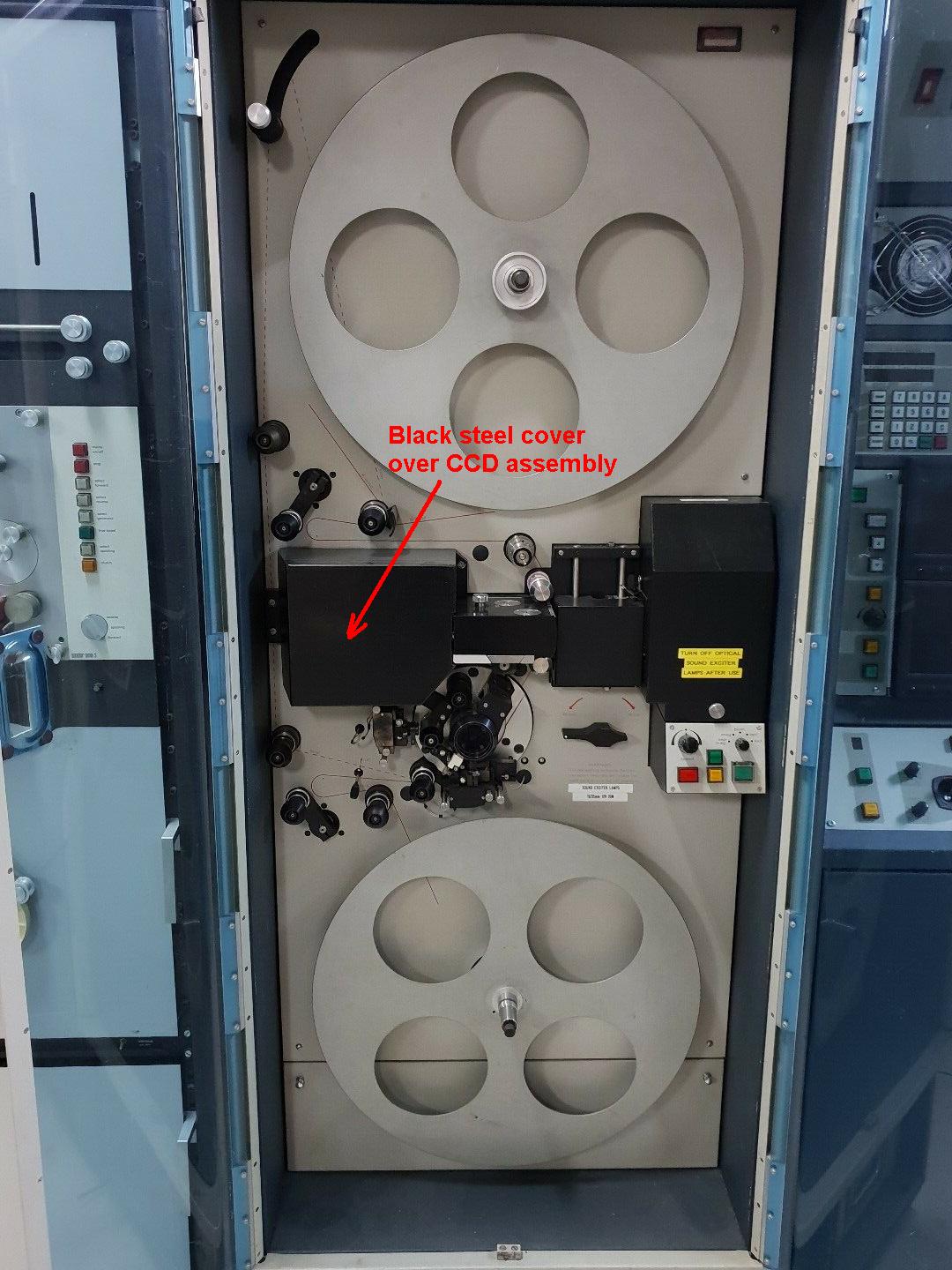
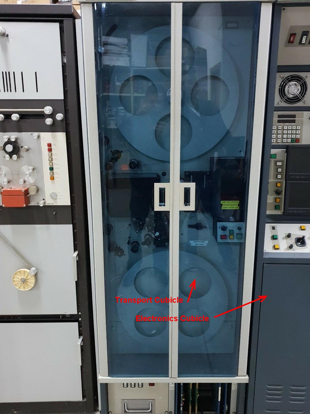
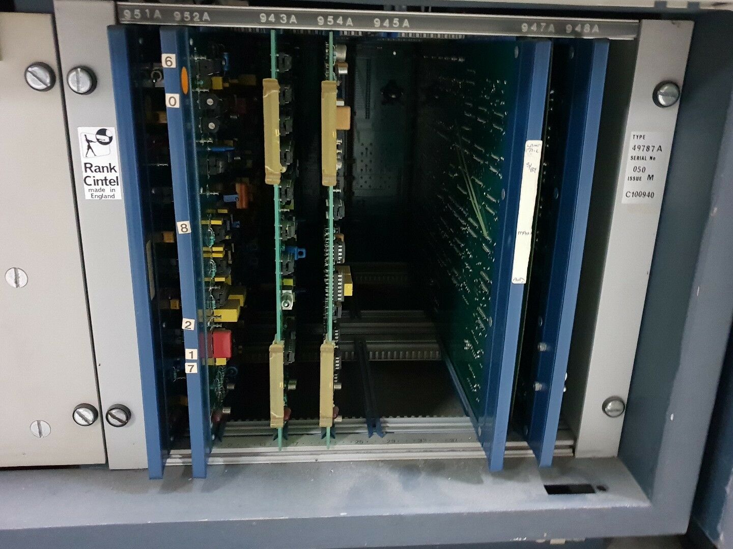
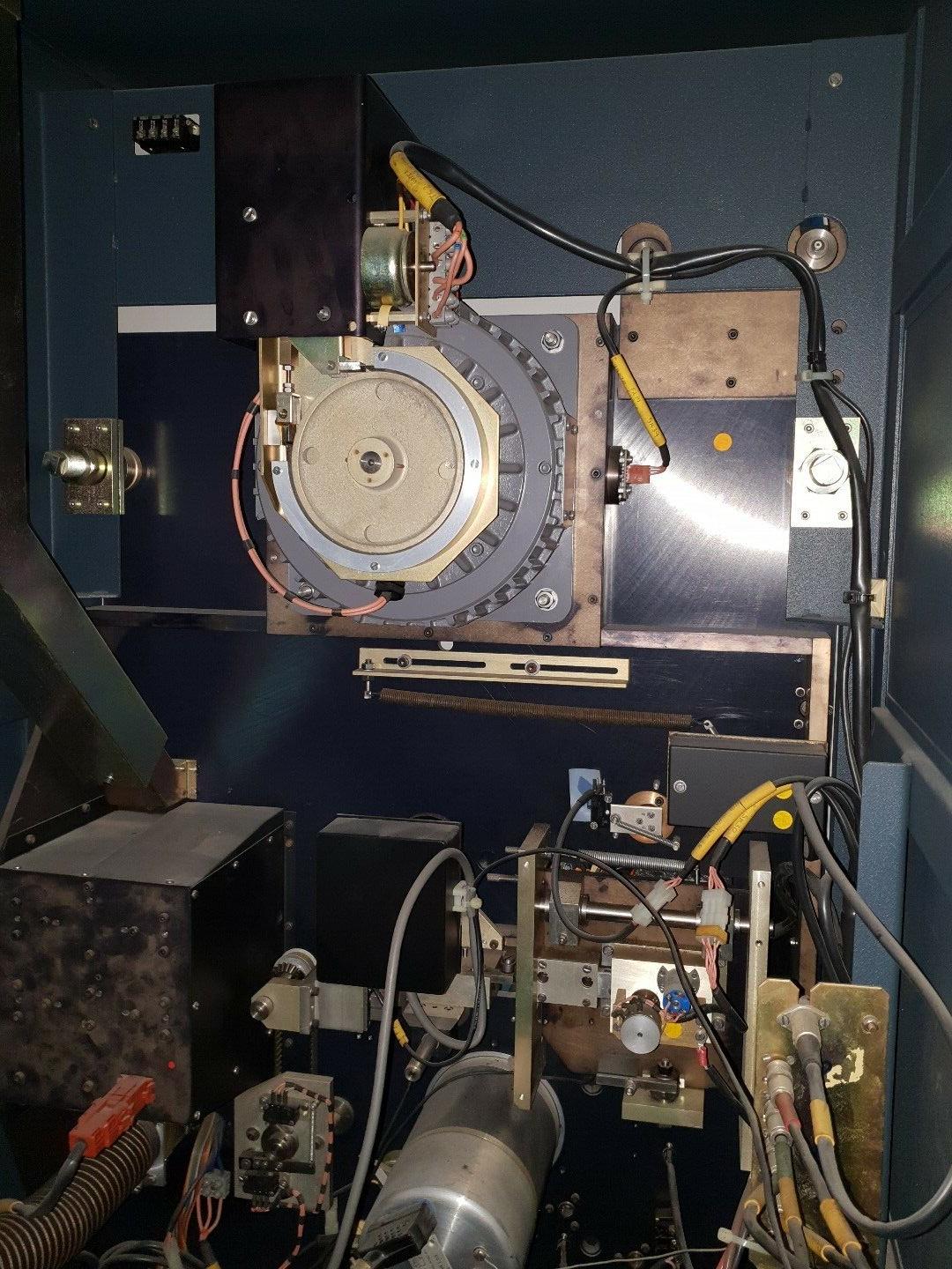
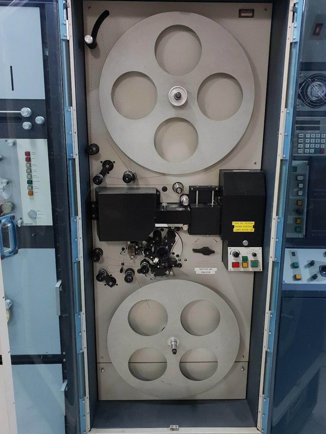
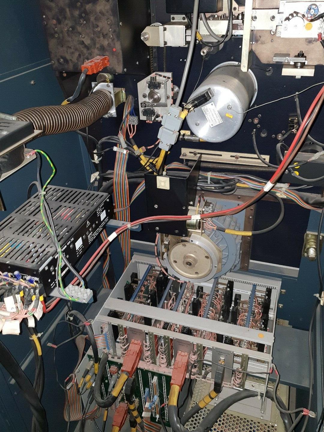
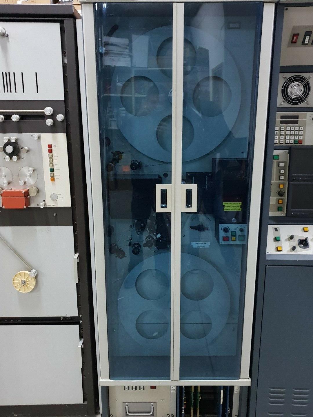
For a long time I believed that I had the last machine. But very recently I saw an ad on big-auction-site for another piece of TV station equipment and off to the side in that image looked like and ADS or ADS2. The seller was located in Israel and yes they do have 1ea ADS2 in PAL format. SO I know for sure as of 2019 that there is at least one more machine in existence. I emailed the seller and he emailed me a few photos. So that makes 2 machines left - possibly the last 2 in existence.
Here are a few photos of the PAL format ADS2 in Israel and I have written some red text/arrows in that email communication:
Rank Cintel ADS2 (Advanced DIgital Scanner) Restoration
(This page created 1/29/19)
Im not affiliated with Rank Cintel in any way- other than owning one of their machines and parts pieces and doing my best to restore it back to good working condition.
The Rank Cintel ADS2 is estimated to have been manufactured somewhere in the year 1987 to 1992. I am at least the third owner of this particular unit. I have spent alot of money and time pyrchasing the machine, transporting the machine, buying parts and pieces and books to complete it (was missing many parts as purchased).
I dont know how many units are still in existence of the estimated 15 total units produced in the ADS or ADS2 series. The first units of the ADS (I call it the ADS1) were made approximately 1982.
I personally own the remains of 2 or 3 ADS and ADS1 units which I keep as spare parts or to use to replace bad parts
1. Electronic Cubicle
A. Cage and circuit boards
B. Control panels
C. Power supplies
D. Ribbon cables and connectors
E. Odds and ends misc
2. Transport Cubicle
A. Cages and circuit boards
B. Some Power supply parts but not all
C. Extra film gates some with better plastic than others
D. Ribbon cables and connectors
E. Odds and ends
F. A few CCD assemblies and some spare boards
G. Quite a few reels in various sized and formats
3. Books and manuals and service manuals for ADS1 and ADS2
The seller of some of my parts REFUSED to transport the heavy steel chasis and unfortunately wasted those parts. IM STILL VERY UPSET ABOUT THAT.
Some people do not appreciate what they have!!!!!!!!!!!!!!!!!!!!!! The saying - "One mans junk is another mans treasure" - applies here.
It is amazing how much space is taken up with piles of boxes of all of the misc parts and pieces to make a unit- it takes up a substantially GREATER amount of space all disassembled. That was not my choice and I asked over an over to please not dissasseble- an that I would gladly buy the whole unit. But NO. So I had no choice - the parts and pieces were the ONLY way for me to acquire his machine. Sad tragic end to a wonderful machine - and that same seller did that to several machines.
On the one hand Im lucky to have purchased spare parts. At the time I purchased everything (over the course of 4 years) the seller was having more and more issues with his machine and was running out of good parts/boards to swap-in and he had already estroyed 2 machines to make a third good one. But alas that third good one was having red-flaring-fringe and he decided to scrap the whole thing. I purchased it all just before that happened.
My limited funds )mostly Paypal Credit) were really pushed to the limits in this purchase over 4 years and I struggled to come up with funds/paying off those high interest debt - otherwise it would all be in the landfill.
ISNT THAT IRONIC paying big bucks otherwise it would be garbage. That is unfortunately the thinking process of the parts-dealers-scrappers-etc. They would much rather not sell to you at all than sell it cheap.
This machine was engineered with mostly off-the-shelf components and IC chips and this makes the machine repairable. The circuit boards are mostly all socketed for IC chips. YAY!!! HOORAY!!! The manufacturer socketed the IC chips. GREAT JOB!!!!!
I have over the coarse of several years purchased NUMEROUS test equipment with this machine's restoration as the main focus. The collection of IC testers and other test equipment are found on my webpage here:
http://www.drviragopete.com/electronic-parts-testing-service.php
I even purchased the HOLY GRAIL of IC testers the Kitek/TESCA Universal IC Tester which tests both Linear and Digital ICs and has a very long chiplist. It is the ONLY IC tester in the world that I know of which is able to test the CA3046 IC which this Rank Cintel machine is just absolutely FULL of this IC chip.
This CA3046 is a wonderful thing that Rank Cintel did - in my opinion. Inside of each IC there are 5 transistors. Thats all just 5 transistors. And rather than soldering/desoldering bad transistors- just replace the chip. Nice clean elegant solutuion. A prepackaged transistor on a chip. Nice solution except there is no easy way to test the transistors- EXCEPT that the Kitek/TESCA IC tester has that function built-in. NICE JOB!!!
There are several ways to figure out which board/part/component is bad
1. Swap in a known good board
2. Check component by component
a. lissajous pattern tester
b. component teter
c. multimeter
d. IC tester
e. ESR tester
g. switchbox tester for CA3046
3. Educated guess on which board/part/component is bad by the symptom
4. Obvious poor appearance of part (swollen capacitor etc)
5. Use the manual to check voltages and oscilloscope patterns
6. Use the extender cards to bring out the card beyond the cage for testing (yes I have these extender cards)
Unfortunately all of the part/boards that I received were already used to swap out or gutted from a non-working machine or a machine with issues.
Unfortunately- the machines that were parted out were "fixed" by tweaking and adjusting out the bad symptom through potentiometers. These tweakers were highly paid 3rd party repair technicians who flew-in and paid thousands for their time. But no boards were changed out - instead the symptons/issues were tweaked and adjusted back to producing a good image.
The seller of my parts tried to pay skilled technicians to once again get his last machine to work and they were unsuccessful in tweaking out the red image fringe- so he gutted everything. My point is that even my spare parts are someone's junk that would be discarded if I didnt purchase.
My philosphy is that EVERYTHING IS FIXABLE. Rank Cintel made a socketed IC machine with almost all components commonly available off-the-shelf components. My hunch is that this machine can live again and be fully working. That is my goal for this very rare forgotten machine.
I see NO OTHER mention or references online about this machine.
Rank Cintel is mostly known for its "flying spot scanners" but the ADS and ADS2 have linear CCDs and use an entirely solid state circuitry with no vacuum tubes. Im not knocking vacuum tubes for scanning - as I have a collection of Kodak VP-1 and VP-X flying spot scanners which work wonderfully also. Flying spot scanners use a CRT with a moving white dot which is focused on the film and then a photomultiplier tube(s) reads the color and builts the scan that way.
But the ADS does not have a vaccum tube - it uses linear CCD array chips and even one for dust and scratch concealment. Its very very advanced - hence the name. Ive seen the output from the seller of parts' video demonstration which I paid for- and the image quality is Hollywood. And that is the purcpose of this machine transfering Hollywood films to videotape, laserdisk, videodisc, DVD, Optical disc formats, files, etc I couldnt believe how sharp and clear the image was in those demostrations. I cant believe he scrapped that beautiful machine - how sad and picky. How terrible those technicians were that didnt have the skills to fix that machine. What a loss.
For a long time I believed that I had the last machine. But very recently I saw an ad on big-auction-site for another piece of TV station equipment and off to the side in that image looked like and ADS or ADS2. The seller was located in Israel and yes they do have 1ea ADS2 in PAL format. SO I know for sure as of 2019 that there is at least one more machine in existence. I emailed the seller and he emailed me a few photos. So that makes 2 machines left - possibly the last 2 in existence.
Here are a few photos of the PAL format ADS2 in Israel and I have written some red text/arrows in that email communication:
Update 5/17/19
After taking a nap, I had an AHA moment and decided to work on my Rank Cintel ADS2 which I didnt have any freetime for months/years.
I started by clearing some films/test films, and cores and misc parts like extra filmgates etc which I was storing inside the blue doors and put them into well packaged labeledd boxes with custom foam pieces and ziplock bags for safety.
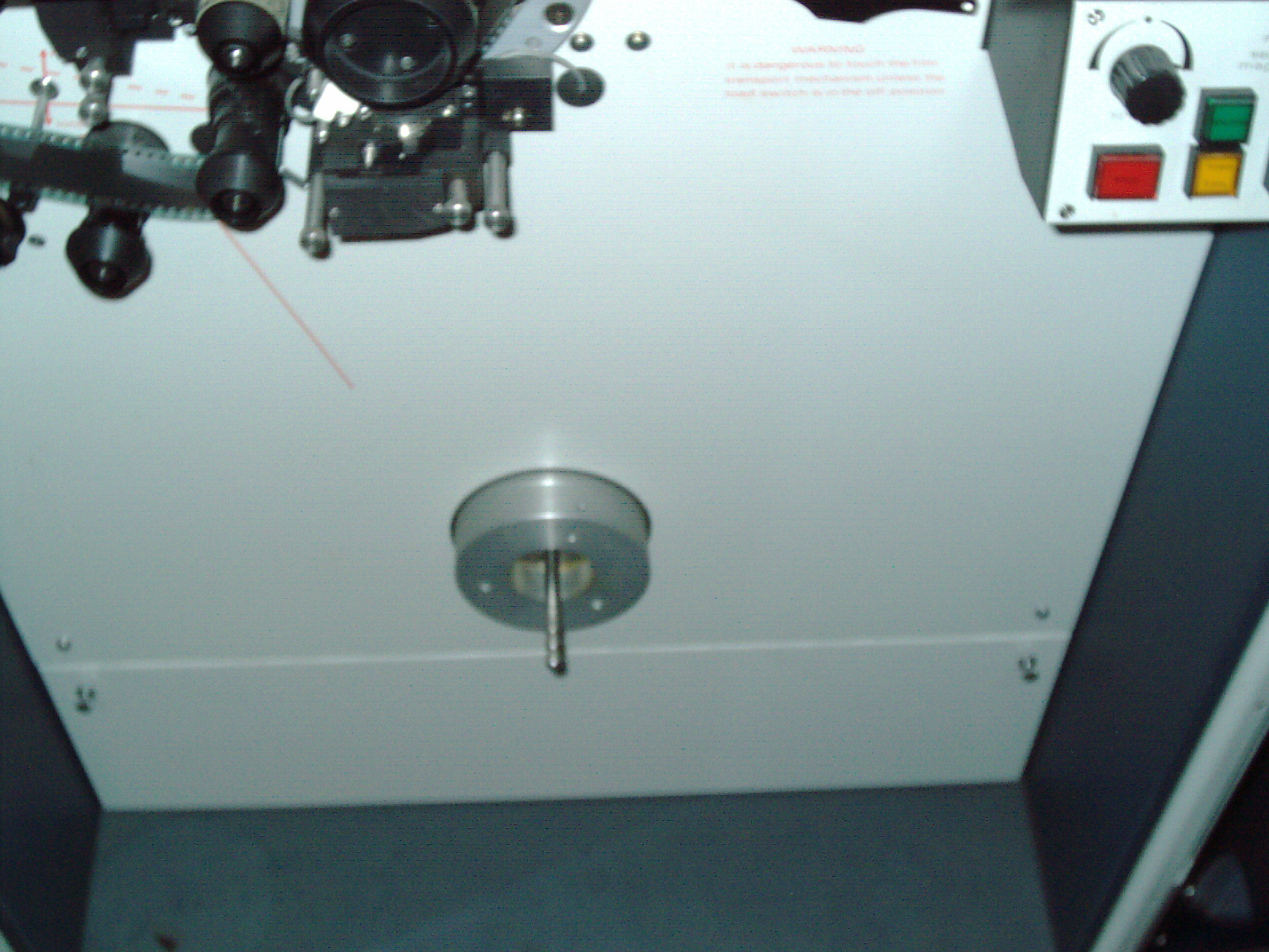
After I had cleared and valuume the inside of the blue doors, I started by trying to figure out how to remove the bottom 35mm reel as I was unsuccessful in previous years. I manage to remove it by pressing on the reel hub and the whole motor pushes in about a quarter inch. Then the knurled end which looks like a nut I was turning clockwise and then counter clockwise and somehow it released very easily andd the reel came off. See it wasnt stuck at all I just dint know how to remove it. I still dont know how but since the special 35mm reel came off I didnt want to get it stuck on again by playing.
I see that the left side thumbscrew was not holdig at all on the left side but the right side is holding. I unscrewed these easily and the door panel flippe down with a hinge at the bottom. Those thumbscrews were not thumbscrews at all an were not removable- they have a sliding tab an the more you turn it the closer or further away that tab gets- in hindsight the left thumbscrew was simple not turned enough. After the door was down I played with teh thumbscrews and figured out how the lever works. I never messed around with this door or reel and these were leftover from the previous owner and how it was left that way.
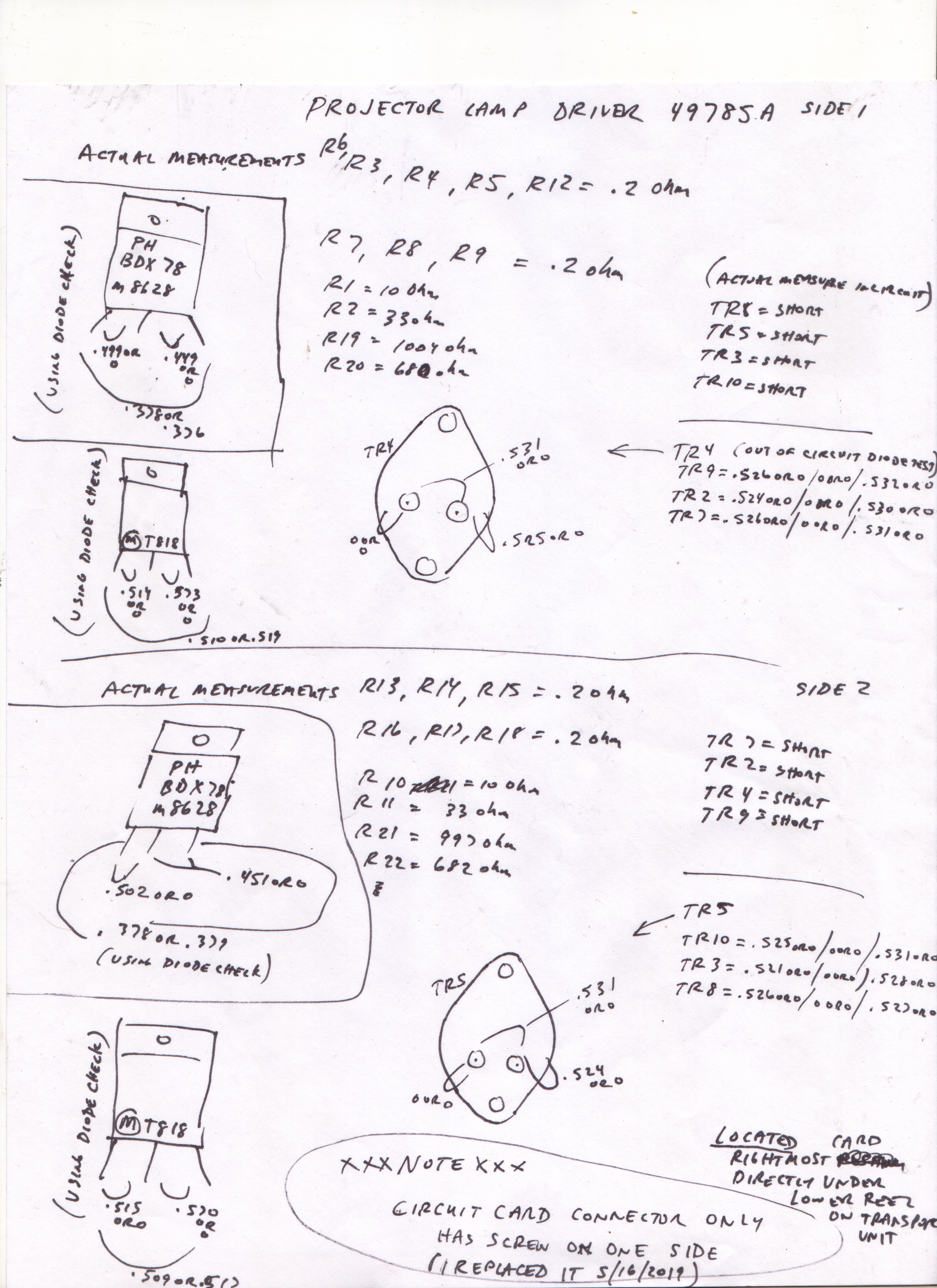
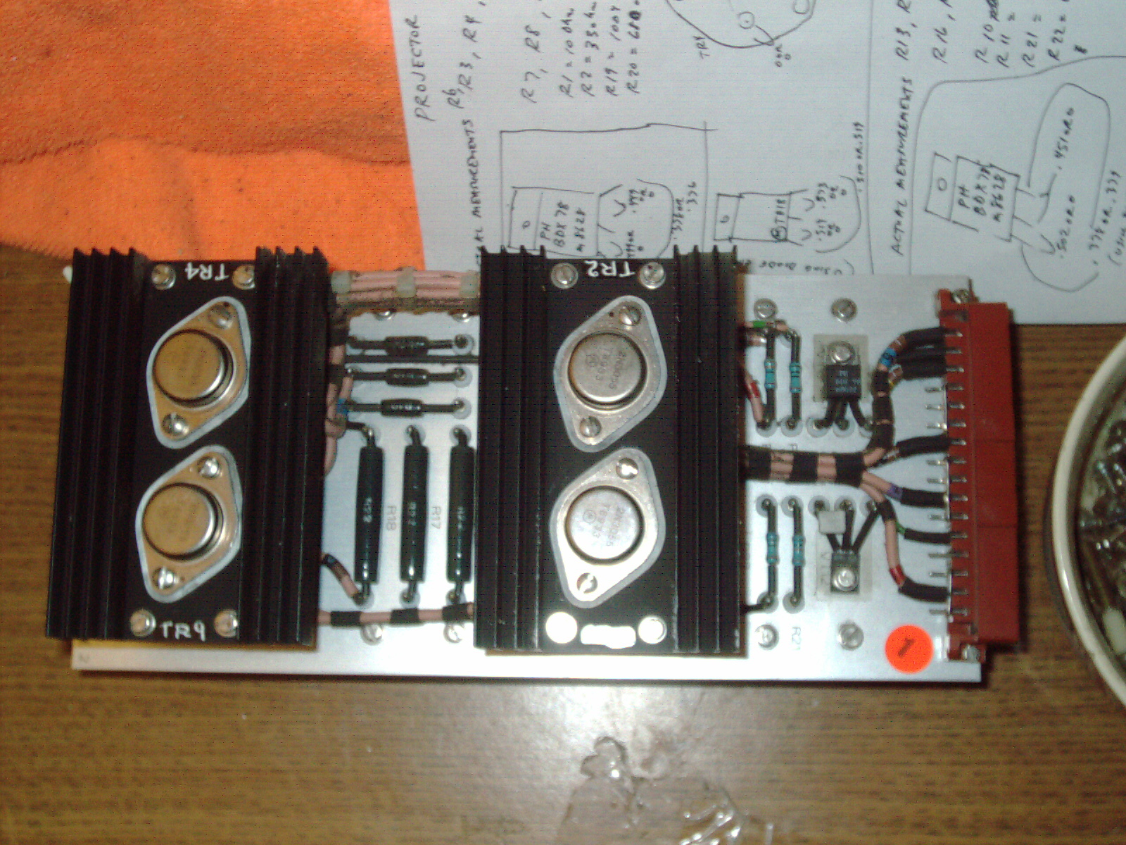
I will scan this notes page and post it here:

|
Rank Cintel ADS2 Test of Lamp Driver Board in transport unit 051719.jpg Size : 8470.476 Kb Type : jpg |
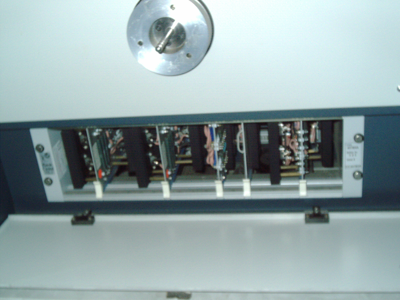
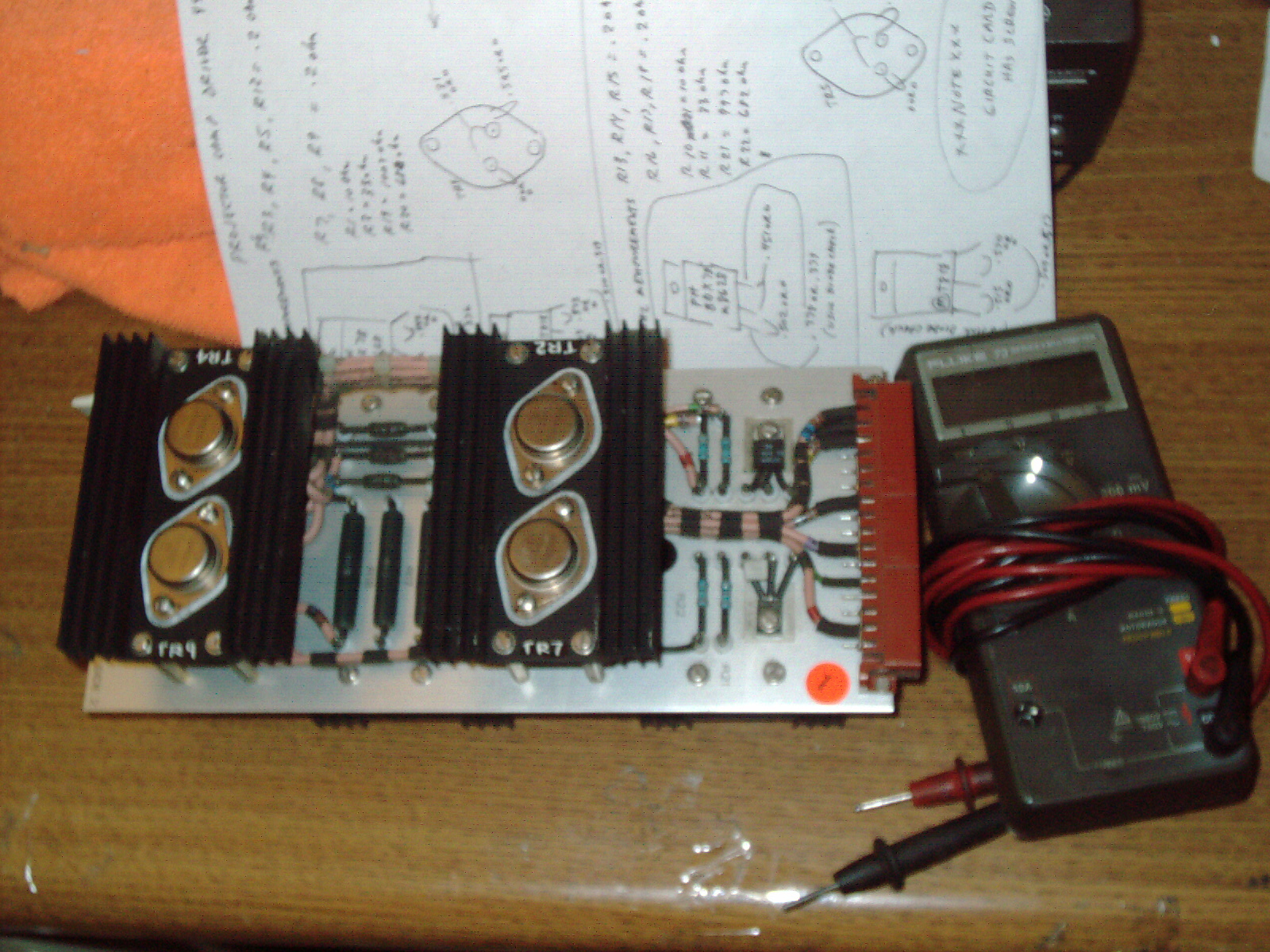
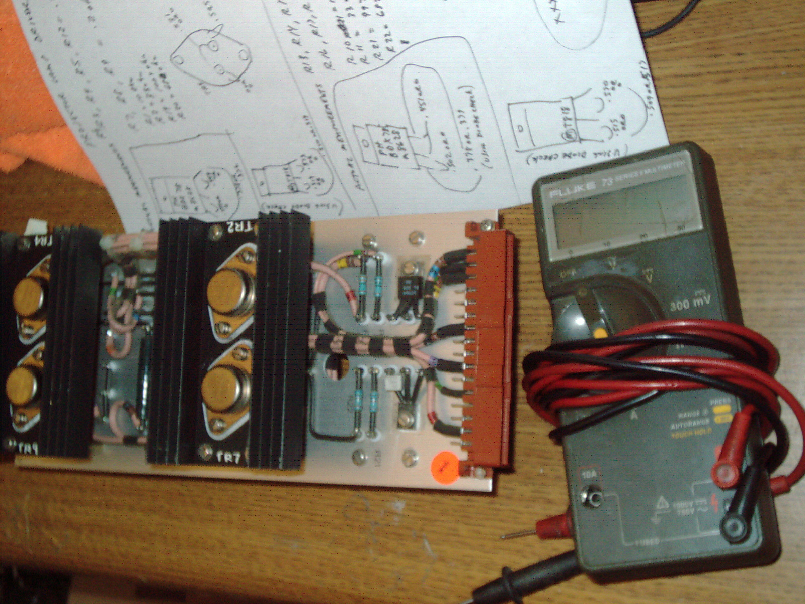
I started by pulling the right most card and actually that was the right board to pull as it is the LAMP DRIVER board. I emmeiately took this board to my electronics test bench and used my FLUKE 73 multimeter to test and record on paper resistor measurements and diode mode test results. I see that the transistors all showed a dead short while tested in circuit so I pulled each and every one and tested out-of-circuit and they all tested good. I carefully put it all the same way it was before and reused the existing thermal paste and mica under each transistor. I also carefully dusted the board with a harbor feight 1" beige paintbrush.
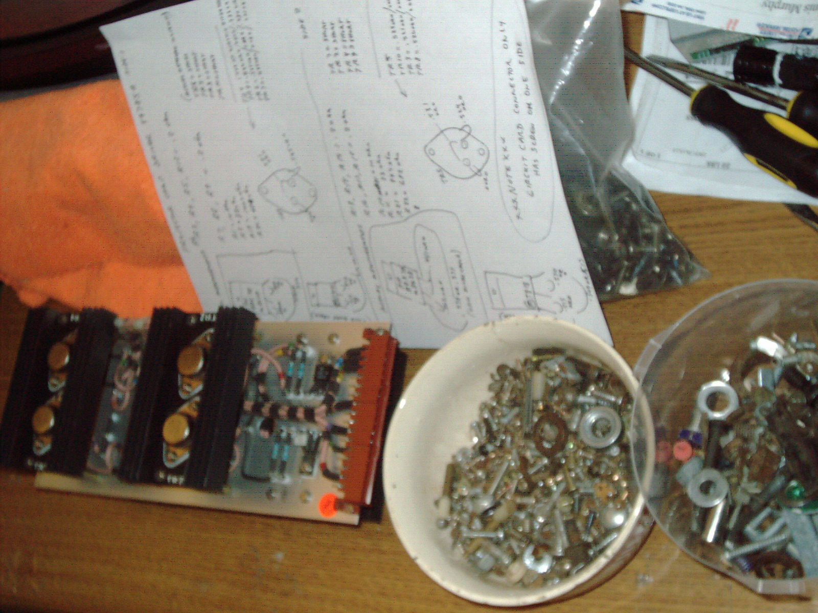
I was so sure that there was something wrong with the Lamp Driver Board and none of the components tested bad. I noticed that there was only one side of the connector and went and pulled the board next to it to see if that one had both screws installed - and it did. I pulled the other board in that card cage and inspected that each one had two screws holding the connector.
I then decided to look through my huge collection of screws and nuts and washers which I had scavenged off of trash picked items in the 1990s to 2000s and I did find a very similar screw and nut to install.
I havent powered up my RC ADS2 yet (for several years) as I noticed some dust under the cars and on the fan in there. Also I will try to seatrch for a screw and nut to see if something fell own there for the previous owner.
I have a hunch that the connector was not connecting properly for this missing screw. When I tested it last several years ago and the lamp lit it was just lucky it lit. Somehow the conector was no longer connected. By adding a screw and nut then the connector will be a drastically better electrical connection- that is my hope.
My next step is to clean and inspect for fallen parts down there. Im an carefuly systematic repairer so I will think about what to do next and will need to figure out how to inspect and clean that area before ever considering powering on.
As I pulled the other cards in that same card cage I did find one more which had a loose screw on the connector and tightened it. I also dusted the other cards with the same paintbrush.
Dr Virago Pete
(847) 454-7858 between 11am and 7pm daily
drviragopete@att.net
Illinois USA
This page last updated October 18 2025