Got a Question?
Here is a paypal button for $10 Quote Consultation Fee. This covers my time in phone or email communication. Speaking writing and download/upload photos takes time. I charge for my time and services. This $10 does not apply to any parts or services and is non-refundable. I find that this tends to screen out 99% of emailers/callers. The 1% of emailers/callers are my buyers. I reserve customer service and technical answers to buyers only. I reserve the right to say no thankyou or to charge more due to the complexity of the question etc. I perform repairs and or diagnostics service for -circuit boards/parts etc. BUT no repairs and no diagnostics testing services are included in this $10 Quote Consultation fee.
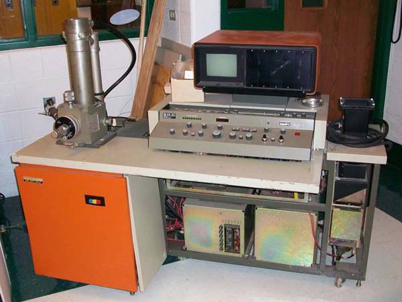
Dr Virago Pete's Scanning Electron Microscope
International Scientific Instruments ( ISI )
ISI SX30 Scanning Electron Microscope ( SEM )
I am not affiliated with the ISI mfg in any way - other than I own one of their machines and seeking to restore it.
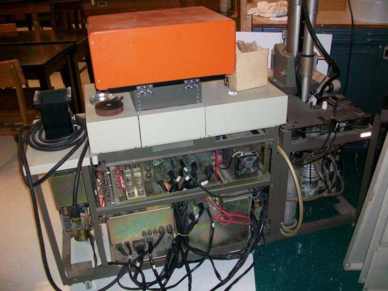
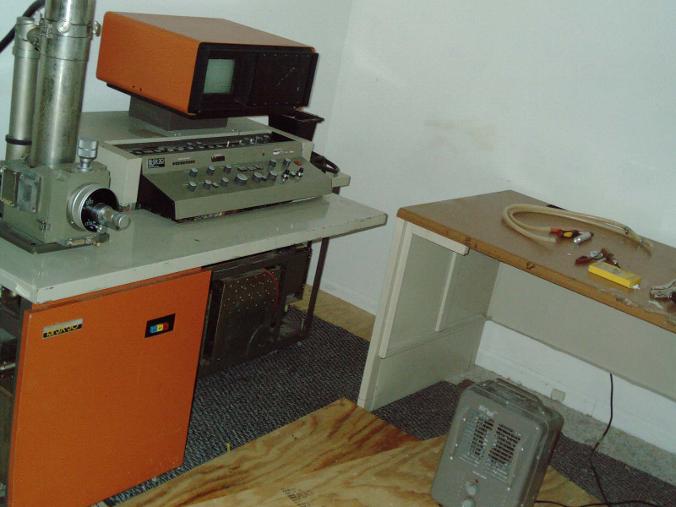
Here are the photos from my machine at the High School it came from.
I hope to find a source of used parts for this machine. I dont know yet what it needs. But as I delve into this machine - I hope that people-who-part-out-their-machine will contact me so I can get a quote on needed parts.
Here is the nicest comment about this microscope - which I found online
"Good resolution and image quality over wide operating voltage range (5 to 30 kV) •- 60 Å at 30 kV in high vacuum"
A Little Math Here:
1 Angstrom = .1 Nanometer
60 Angstroms = 6 Nanometer
Gold atom = 0.1441 nm radius (rounded)
Gold atom = 2.882 Angstroms approx size (rounded)
(There is alot of wrong/contradictory information online and in books so I dont actually know if the diameter of gold listed above is correct)
So, under ideal conditions (antivibration floor) one pixel on my screen will be 20+ atoms wide and 20+ atoms tall. I did place my machine directly over a steel girder I-beam just below the flooring - and the machine has built-in shock absorbers - I hope those two things will help the machine achieve its maximum magnification through stability.
Im estimating an approximate 150,000 x magnification maximum under ideal conditions (that was achieved by ISI installers a 70A guaranty - per the manual) Given that the monoschrome CRT screen size is only about 4" diagonal and the Polaroid camera print is about the same size.
60 Angstroms (6 Nanometer) is good for a microscope this size. The above may or may not be accurate as I found that review of this machine online (the ISI SX-30E manual which I have - says the mfg guaranteed min 70A at time of delivery/installation - that is astonishing considering how small this microscope actually is compared to much larger microscopes)
Parts Needed
1. Replacement parts for Secondary Electron Detector
2. Roughing pump
3. Manuals
4. I dont know what else
Parts I have
1. The SX30 machine and the column as pictured
2. Several 3 Ring Binders of notes and instructions (for ISI Super IIIa - a different model and very general)- all very thin and I may not have all literature - so if you have books and docs - let me know
3. A small cardboard box with parts and pieces and a few filaments
4. Secondary Emission Detector which was dangling when I picked up I marked it JN1 as it was connected to JN1 connector. I am working on restoring this sensor.
5. Alot of Steel panels (side front back etc covers - removed by previous owner)
My Notes on Parts Acquire Progress
1) Jan 2014 in discussion acquire digital image capture device which is DOS based possibly adaptable to ISI - I will need to locate schematics and port pinouts for ISI to adapt this board as it was originally intended for JEOL. Craigslist ad Wanted posted.
2. The seller has sent the circuit board and a CD-ROM for digital image capture (in transit at the time of this writing)
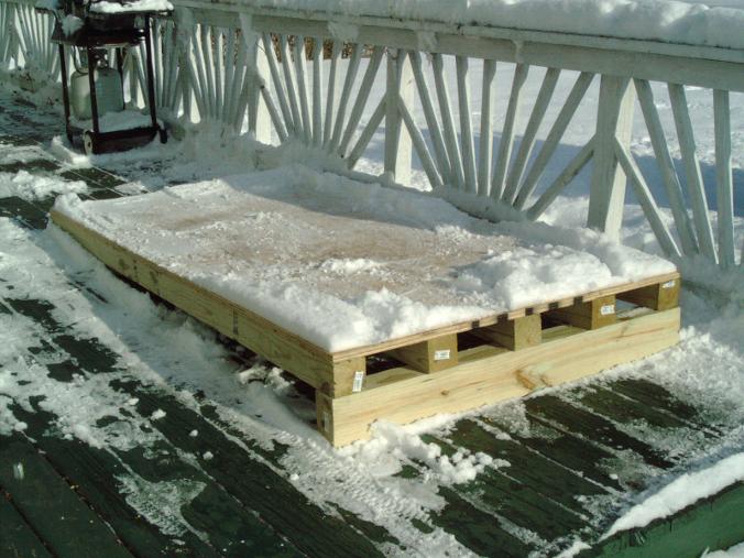
3. 1/12/14 the ISI SEM is indoors and off my trailer and out of the cold Chicago area winter where it was exposed to a record breaking minus 50 degrees F "Polar Artic Vortex" and then 2 days later the weather was 37degrees and slushy melting the 17 inches of snow. During this 90degree approx temperature difference (-50degF to +37degF) the SEM was moved indoors and is resting on a 1/2" plywood sheet to protect the floor from the extreme weight and allow rolling the machine to access the backside and all sides for rstoration work. It has been outdoors under a tarp for 5 weeks (Purch early Dec 2012). The extreme weight meant a ramp needed to be built and then dismantled and then the wood from the ramp re-used to make bridge over the doorway and then re-use the wood under the SEM to support its weight indefinitely. So it was quite a challenge geting it off the trailer and into its spot- A move of only 20ft away. It took 10 men and a Tracktorloader with forklift attachment and $100 worth of hardware store wood and steel hardware and a jetski/small boat trailer to accomplish this and payments to the labor provided. I didnt keep track of how many hours it took- but it was alot of hours on my part. I dont see any damage from being outdoors. Probably the deepfreeze weather prevented extreme damage from humidity because most days were very cold. Some days were beyond cold and are on the record books as the coldest days in history in Chicago area (I'm 35miles North of Chicago). There are some tarnished areas where I saw this at the time of purchase. This machine was outdoors in its previous life, and I saved it from a landfill fate. I couldnt save the carbon coater from that fate because it was just too heavy and big. It probably weighs as much as my SEM. I have included a photo of it here as a download - I dont own this carbon coater but I was offered it for a mere $100 and includes a pump. I just dont the room for it and my small space cant support the additional heavy weight machine.
I am including photos of the Edwards Sputterer which was offered to me by th esame seller. I have no way to transport it - It was a true bargain for $100 but I had to pass on it. I think it is for carbon sputtering as my best guess. This Edwards sputterer was the mating set for my ISI SX30 microscope and I was told the sputterer contains the roughing pump. I will need to acquire a small slow roughing pump to fit my small space. I purchased my SEM from a High School 40 miles south of my location.
Update 1/12/14 regarding Edwards Sputterer
I contacted the seller to say thanks for the SEM and to let him know I would pass on the huge Edwards Sputterer and he replied that the sputterer was sold last week and the buyer "hauled it away" and believe me - I'm sure it wasn't easy to do because it is one big heavy machine. They probably used the same big yellow tractor loader with forklift attachment - the same one used to load my SEM on to my trailer. So the downloadable pictures of the Edwards sputterer are only for FYI as I did not buy it - but it is part of the history of my SEM.

|
Edwards Sputterer.zip Size : 522.617 Kb Type : zip |

Here is an email I sent to the seller of a image capture device called "Image Thief"
The seller said that it was removed from the SEM because it stopped working and they replaced it with some other device - it was originally in a Jeol SEM 5600 but I hope to adapt it to ISI SX30 if possible. The first step is to purchase it (done) and troubleshoot the boards (done) and this is what I found as postential issues:
I did some testing on your Image Thief Board and the DMA card and I see 2 possible reasons why you had an issue a decade ago.
None of those are a complaint- I'm happy as a clam to have this item so dont get me wrong.
I'm just sending this as an FYI because maybe you were wondering what happened a decade ago and why it stopped working.
I
tested the Image Thief and there were 2 chips I didnt have a tester for
but everything else tested fine and was nice and socketed.
I
tested the DMA board and found one chip which gave me a fail only once
and I couldnt get it repeat that- subsequent tests always passed. So I
may attribute that to operator error (me) or possibly an intermittant
glitch inside the chip. Regardless I wrote a note and will save that
information and that note will ride along with the card in its plastic
wrapper for future reference.
Another thing I saw was several
bent pins on the backside - I tested it on an esr capacitor meter and
all the capcitors one by one tested fine. There wasnt any chips which my
collection of testers skipped over on this board. So all socketed chips
tested fine. There are a few soldered in chips which I didint test.
I
usually stop troubleshooting at the very first sighting of a potential
problem and I think this one is big enough to have caused a malfunction.
See
there is a group of pins sticking out on the solder-side of the board.
For some reason someone at the factory was half-asleep and put in a
capacitor only halfway. Then they soldered it in place much much taller
than the other capacitors on the same board. Now functionally - this is
not an issue. However the board came into contact with something of
great force - enough to bend the pins- that takes alot of force to do
that.
The 3 pins are bent over in such a way as to make me think
at least one was possibly touching each other or the U14 chip next to it
- or possibly up against some metal object.
I sent some photos
here and you see the bent pins - I'll straghten them and also desolder
the U14 chip and probably some more chips for testing purposes - but
most likely none of those chips are bad- it is all low volts 5v or
possible was shorted to ground - either way I dont expect to find any
chip errors.
That may answer some questions about why it stopped working 10 years ago for you.
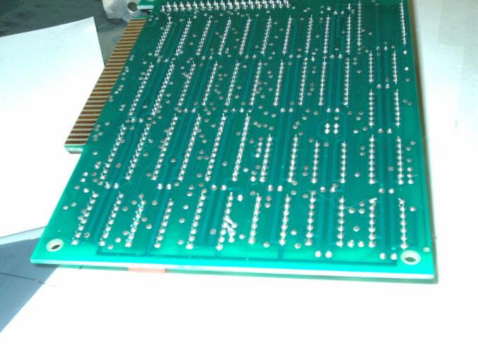
My
photos are not super great but you can clearly see bent over pins and
those pins are from the too-long capacitor which someone didnt trim off
the extra length of legs at the factory.
Here are some photos of the DMA 8-bit board- it shows the pins bent and it is very likely to have been the issue while installed in the Jeol 5600 SEM. I will straighten the pins. The IC chips and capacitors I tested them on my equipmnent and they look fine. WIth the exception of 1 intermittant chip and that may have been my error but nevertheless - for good measure and just to be sure the device is rock solid 100% I will plan on changing out that IC Chip. When checking ICs it is important to notice and pay attention to odd things and those could be trouble spots. I'm lucky I saw it fail one time and I never could get it to repeat. I'm lucky to have seen that. Luck has very little to do with it really - I've seen that sort of thing before. It is a good idea to change out the part.
|
|
DMA board bent pins.zip Size : 4410.188 Kb Type : zip |
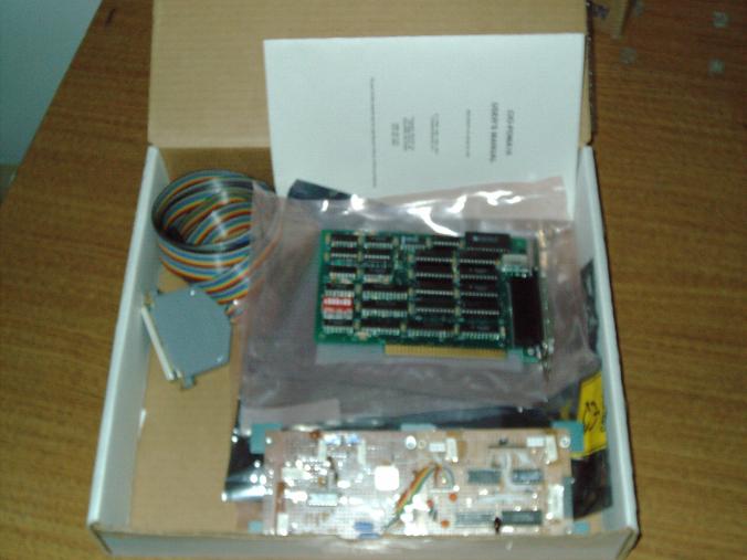
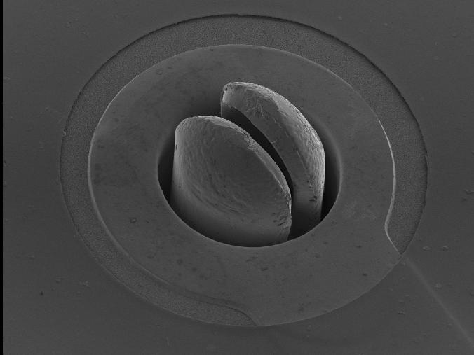
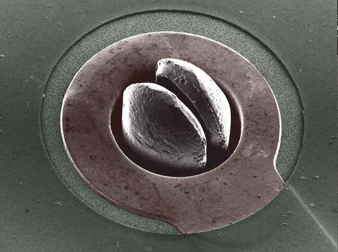
Above pictured "Image Thief" homemade perfboard prototype digital capture board and cable and DMA 8-bit card and manual. This board was used to capture a very wonderful SEM photo on a Joel 5600. I have included here an actual photo that this very board captured ten years ago on a totally different microscope - attached to a DOS Pentium 133 PC. I hope to be able to connect this board to my ISI SX30 and achieve similar photos. I need port and pinouts and schematics to be able to do that. Anyone have schematics or port pinouts for ISI SX30? Here is the wonderful digitally captured photo. It is astonishingly sharp and clear. Wow.
Here is a link to the authors and inventors page - he is working on a USB version and is an open source project. I asked to purchase his old non-working board. I believe it will now work as I tested most chips and found bent pins and straightened bent pins and cut them short/close to board as should be.
It looks like the monstrous cave worm the Millenium Falcon flew into in the asteroid field. But seriously it is not a photo taken by me. The inventor of the "Image Thief "captured this image and is a PCboard trace and island with a component in the hole.
Here is a link to the inventors page and open source project
http://people.umass.edu/~dac/projects/ImageThief/ImageThief.html
I have a penpal and he said about 15 yuears ago or so he built the Imgae tHief and installed it on a Joel 5400 and it worked very well. He said teverything I needed to build it and the softeare and everything was in the downloadables. He made his own board from this download.
I asked the author if he could could sell me a prebuilt one and I jumped at the opprotunity to buy the actual board that made this picture The image measures approx 2000x1400 resolution and is very detailed. The inventor wants help on his open source project and I am not a programmer in assembly language or USB familiarity - but I am good at sourcing parts and people. Maybe a reader will see themselves as helping in the progress of the USB version of the "Image Thief" open source progress.
I myself am going to do my best to get the older DOS version up and running. My microscope is from that same era. Mating my vintage ISI SX30 with a vintage DOS PC is what I intend to do. I suspect this photo was created by using a backscatter detector whereas I will be using a Secondary Emissions Detector so The image iteself will have different highlighting method/appearance.
Another important point about the Image Thief is - I dont see the data infomation such as KV or magnification on the image itself. It leaves the image clean and uncluttered and unobstructed. It is a beautiful image. I hope to someday make an image of this quality myself using SED and in a different subject matter - but nonetheless very comparable quality-wise.

|
pcb_full.jpg Size : 266.013 Kb Type : jpg |
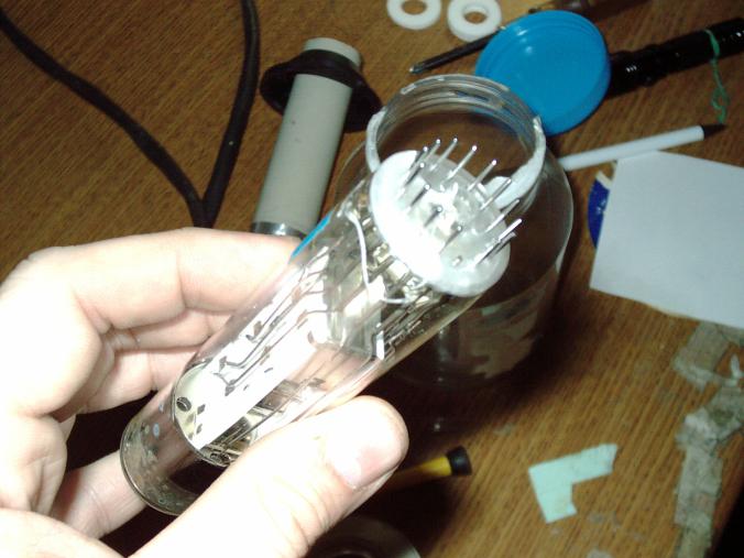
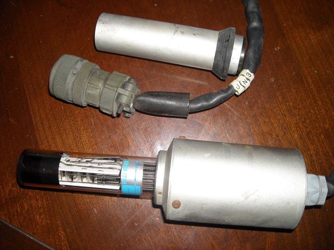
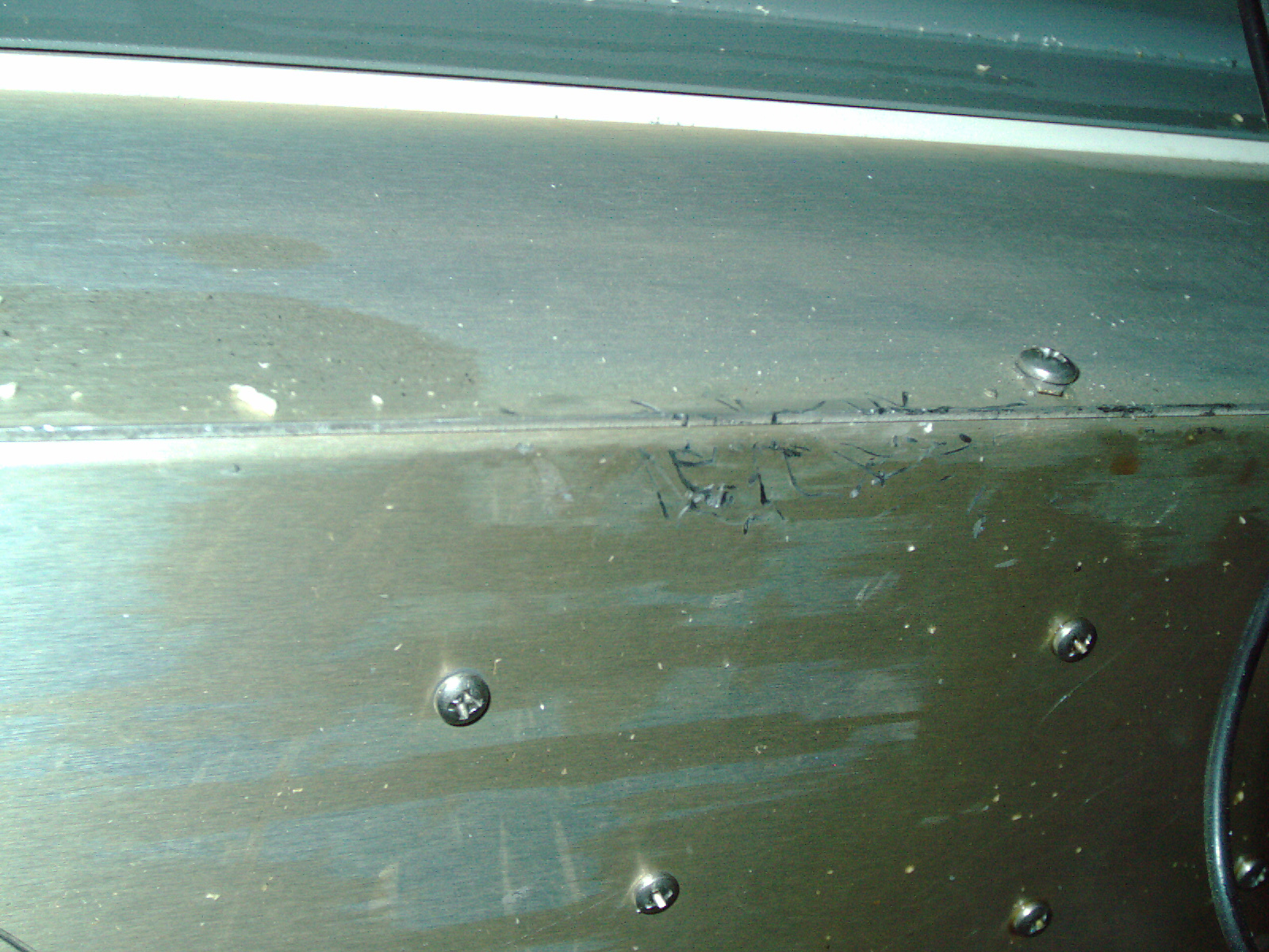
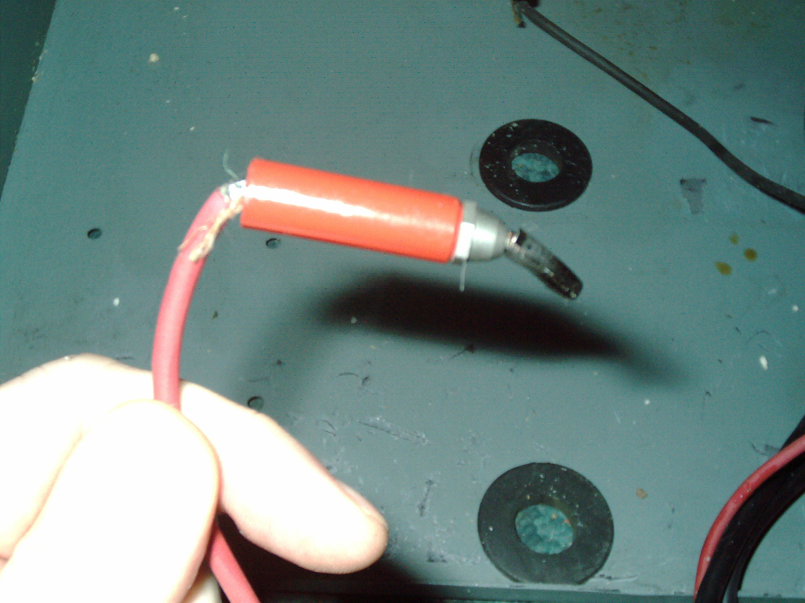
I carefully stored the sensor which the seller said to be careful with - but I found that it actually had been mishandled very badly before I ever saw the machine. The sensor was broken off and because I had never seen an electron microscope upclose or in-person I just assumed that the sensor is supposed to be on the table and connected when you plan on using it- because it was not connected at the school. Its funny that someone told me to be careful with it - when obviously it had been smashed separate from the column and probably dropped on the floor. The telltale sign for me that something was not right was a tiny rattling sound .
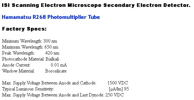
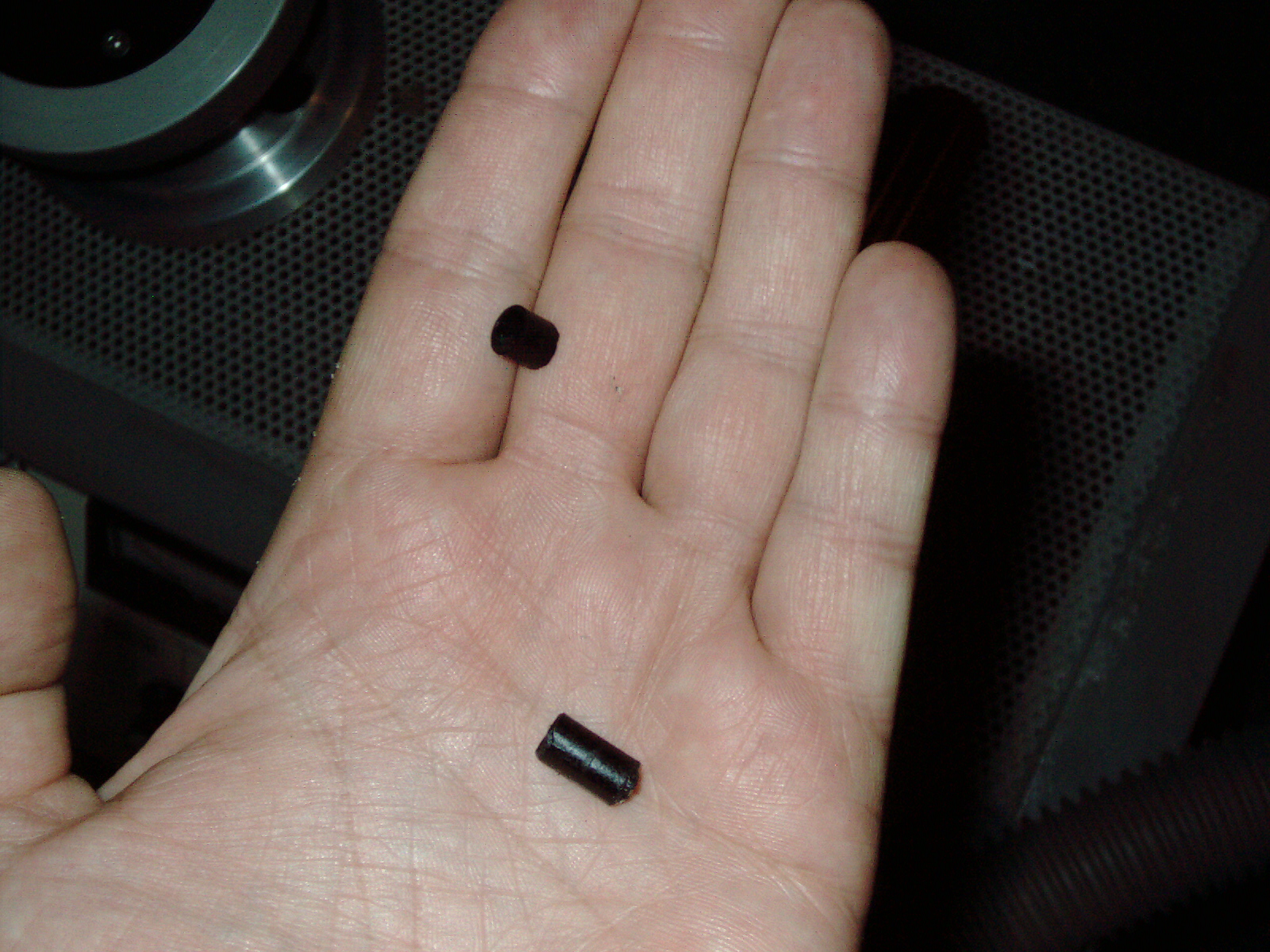
I unscrewed it expecting to find a loose screw and save myself from an electrical short. But it wasnt like that at all. What I found was a tiny piece of glass and this piece of glass was the"belly button" when a tube is blown and sealed by the glassblower or machine. So I knew that the photo multiplier was bad before I disassembled too much. As I disassembled more I saw a large crack and a white cloud ring inside the tube and all of the pins were crooked and bent in all directions. (Is it possibole someone tried to unscrew a vacuum tube as if it was a lightbulb - yikes) Here are some photos, and I need to start looking for a Hamamatsu R268 Photomultiplier Tube as mine is broken from the previous owner bumping into the sensor and it dropping on the floor most likely (or possibly sabotage) I will need to make a replacement plastic mount on my lathe but that is not my big concern - finding the tube is probably one thing that caused my SEM to almost get scrapped. I see an ebay tube with Make Offer and I may try to make an offer on it. I see one sold for $40 back in March of 2012 when I do a google search but I may not get so lucky to find one at that price. Maybe the reader has one they can sell me?
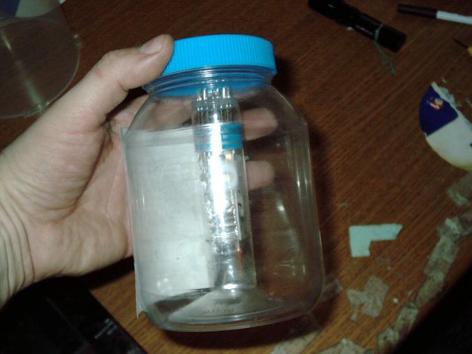
Here are some photos of my disassembled sensor - there is really not much to it at all. I will store it in a plastic mayonnais/salad dressing type jar for safety as the glass shards can be dangerous to my pets. A thorough vacuum with a shopvac for fine glass fragments was also done in the entire area.
Some possible cross reference to this tube made by Hamamatsu - Philips, EMI, Burle, and possibly other brands. If the reader knows of a possible substitute let me know as that will widen my search and make it easier to find a replacement - if there are substitutes from a different mfg.
Some online vendors scavenge old lab machines and find tubes or have an inventory of used or new tubes. I hope to find a replacement for it.
The location / placement of this sensor on the SEM column makes it easy to brush against it if the machine is put in high traffic area where people can brush up against it.
The sensor is basically a light sensor - a very sensitive one. I have 3 photomultiplier tubes in my Kodak Telecine made in 1973 (one for red blue green) but is otherwise solid state. I have read that photomultiplier tubes are extremely sensitive and that is why it is a vacuum tube rather than solid state. The other many PCB circuit boards are solid state with many IC chips and transistors. Having one tube inside of a solid state machine seems a little out of place - but the simplicity of the sensor is astounding that it comprised of a photomultiplier tube and a litle round circuit board with one chip - inside the sensor housing.
I dont know enough about the microscope at this point to give the sensor a name - possibly "secondary electron SE detector"? It is basically a photomultiplier tube facing a glass window (short fiber optic glass) facing the specimen holder. As the electron beam strikes the specimen it creates light and the photomultiplier detects it. What wavelength of light - I dont know yet - probably not visible light.
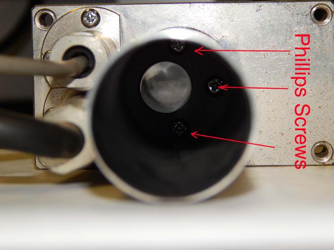
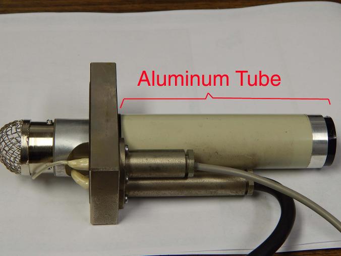
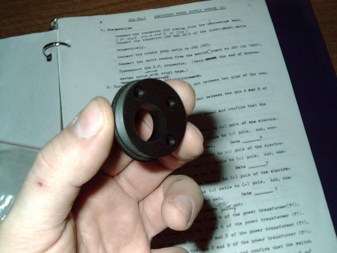
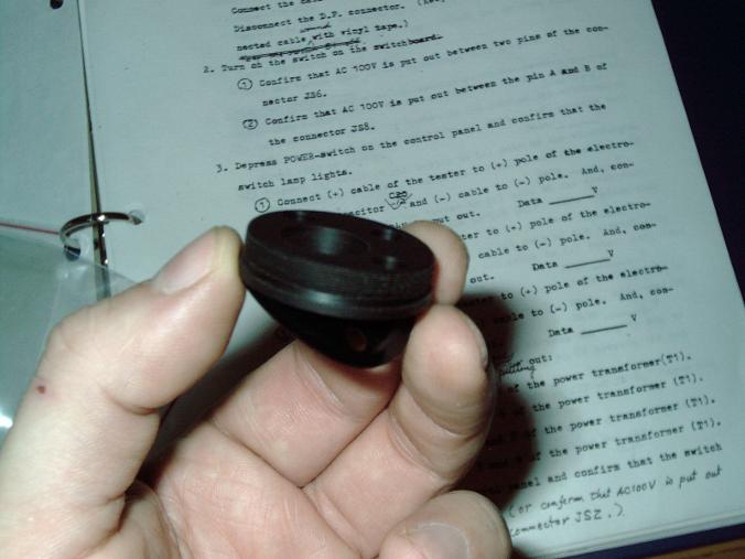
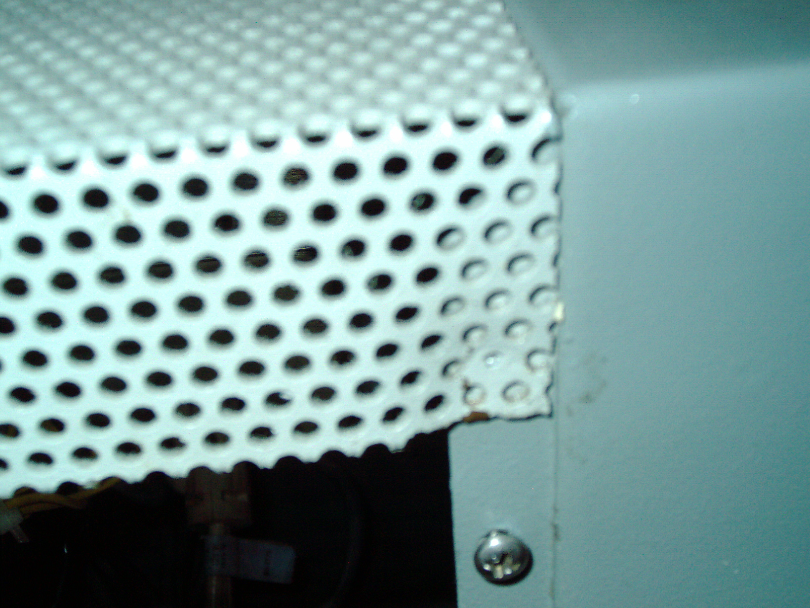
Shows broken off metal can housing from Secondary Electron sensor. See the black plastic round piece that was once part of the mount. When I first got the SEM I thought it was a round gasket - but no it is part of the plastic mount. This is the way I bought it. No damage was done by me. I either need to find this round plastic piece as a replacement part or fabricate it myself or epoxy it back together and stregthen it. It is most likely an electrical insulator - I cant image that the factory arbitrarily decided to make it from plastic when almost the etire machine is metal. So I would imaging it is an insulator. As a replacement a phenolic or glass-filled high temp plastic would work. Since this plastic piece is right next to the hot PMT tube - it needs to withstand heat. The edges of the round aluminum tube are crikled like like someone tried to straighten it. There are ridge rings inside of the aluminum tube where the round plastic piece is. This means it gets pressed in place and the ridges keep it there. The plastic round black piece isnt intended to come out as once it is pressed in there the ridges lock it in place. Maybe there is enough ridges left for me to apply some epoxy and then try to repress the aluminum tube over the repaired plastic.
The boogered up end of the aluminum tube makes me thing that I need a tube expander to do a good job to straighten the tube end which is crinkled and attempted straighten by the previous owner.. I purchased a muffler/tailpipe expander last year and it may contain a mandrel of the right size. I'll have to ckeck on that.
You would thunk that there would be some kind of guard surrounding these sensors sticking out th eside of the column since they are so delicate and someone bumping in to them is a real possibility. I will consider welding on some type of barrier between my room entryway door and the SEM as I dont want this to happen to me years down the road after I had already fixed it.
See the socket for the photomultilpier tube
Hamamatsu R268 Photo Multiplier Tube which I need to find a replacement as it is cracked. Pins are bent in all directions - when this was broken it probably made a big crashing sound and a loud pop when the glass broke. I hope I can find a replacement tube. I can fix the mount and the metal housing.
Photomultiplier tube is sometimes written Photo Multiplier Tube or PMT for shorthand.
I was communicating with a scavenged parts supplier for SEM microscopes and I ordered a replacement used tube which has the black round plastic piece and an ISI SX30 200page approx Service manual. I am happy with the price negotiated for these 2 items. Here is a picture of this aluminum tube (I have not received it as I am writing because it was just ordered today 1/23/14. This seller also had a glass vacuum tube R268 Photomultipier tube but the price was beyond what I can afford. I will need to search for another source for this. I have maxed my budget for while.
I will need to figure out a way to protect this aluminum tube from being leaned on or brushed against as I may not be so fortunate to find another one in the future. I may need to weld a brace onto the frame so that a protective shield encases this delicate perpendicular sensor which is resting on a very thin plastic plate held by 3 philips screws. It would not take much to shear it off. I can imagine the gut wrneching feeling that would have been for someone to have destroyed an SEM microscope with an elbow or a backpack brushing against it (possibly - who know what really happened).
I saw a very rusty ISI SEM column on an auction site
I read that SEM columns are made of stainless steel - the author was not correct. Columns are made of steel with a decorative plating. The frame is steel. The control panel is steel. The electronic enclosures are steel. Lots of steel. Very little plastic. I dont see any stainless steel- maybe there is a piece somewhere made of stainless steel - but the column is not stainless steel. The author of that article was wrong about the column being made of stainless steel. I saw a very rusty column on big-auction-site which the plating was being pushed up all over due to the underneath rusting of the steel column. The fact that it was so rusty - tells me it was steel and was outside in a boneyard for a long time.
Also is visible the thin black rubber gasket which goes behind the round plastic piece. The gasket came with my replacement parts. I'm glad to have purchased these parts.
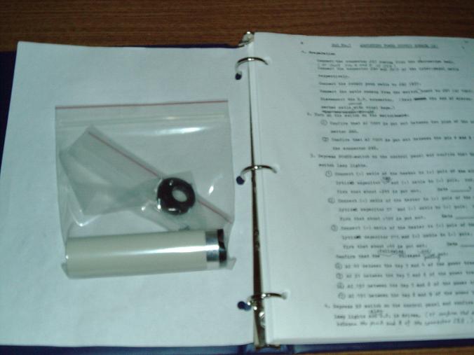
I ordered and received 1/2014 the replacement aluminum tube and also the black round plastic piece (from scavenged parts supplier) which goes on the end of the tube. The plastic piece is a mount for the tube to be attached perpendicular to the column. These parts are from the Secondary Emisssions Detector. I am glad to have these parts to replace my broken plastic. In addition I purchased a technical manual (from scavenged partts supplier) for ISI SX30 which shows adjustments for voltages and pictures of waveforms. This 200page 3-ring binder book jumps right into the adjustments and calibration but I feel there is proabbly some other book which I'm missing still.
I dont have schematics or an overall layout of which parts and pieces should be in this ISI SX30 microscope. I dont have a port diagram or pinouts showing me the data for each port- which is really what I was asking for but still this book is a great help to me and I will be able to check voltages at the power supplies etc. But I will continue to look for more books - maybe a reader has a book they can sell me?
I see a couple of things not attached to anything and I'm scratching my head on whether something should go there or not.
I plan on making a video showing the ISI SX30 with the panels off and pointing out the parts that I need clarification - maybe that will help to identify what needs to be purchased for it.
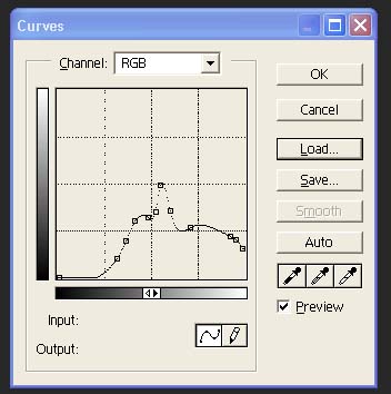
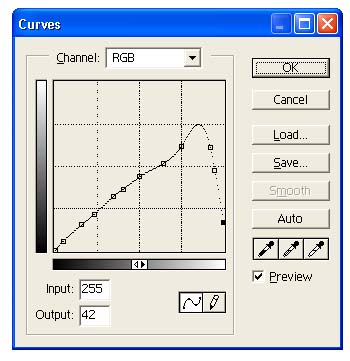
I always liked how Secondary Emissions images looked like as they have a surreal metallic looking appearance. Where Backscattered images look like light-photographs and closely resemble how our eye sees. Secondary Emissions created photos have a SCI-FI look that is hard to describe -except that there is a white outline which sharpens images and sometimes shadows are white rather than black. It almost looks like a combination of a positive photo and a negative image all rolled-up into the same image. I played with Photoshop 5.0 to duplicate this SEM Look of Secondary Electron Images or to correct it to look more like Backscattered images and what I found is that if I go into "Image/Adjust/Curves"
I find that images which are created on a Secondary Emissions Detector can be made to look more like Backscattered created images by using the above curves (I invented this process (C) Copyright2014 All Rights Reserved) and I believe that it is due to the clipping or attributes of the image sensor. The above curves reverse the trend for shadows to be white- they should be black to look more like our eyes see. Instead the sensor at a certain point starts to display shadows as shades of white. The above curves reverses that. Now depending on the SEM the curves are in different points on the graph but the idea is to find the point where that SEM starts that white shadowing and then make the curve sharp in that spot - this "fixing that image" to look more like a backscattered image.
I actually like how Secondary Emissions Imags look - so dont ge me wroing when I say "fixing image" as the surreal look is quite amazing and I like it alot. Because I understand graphics - I recognized this as a function of the curves within Photoshop 5.0 and later versions have this too. I sometimes began with a photonegative of the image or a positive of the image - it possible to work these curves from either positive or negative. Easy to flip positive/negative in photoshop by "Image/Adjust/Invert" also since SEM images are grayscale making the image grayscal helps "Image/Mode/Grayscale"
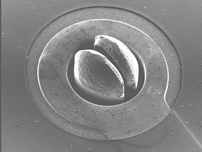
The above image was redone in Photoshop to create a fake pseudo Secondary Emissions detector image - made from a Backscattered detector created image. I used the above curve to create it and then brightness and contrast to give it the correct overall correct tonal quality for viewabilty. See how the details now stand out so much more pronounced. It is my hunch that the SED and Backscattered detectors have different curves and this is transposeable between images produced from SEMs with Backscattered or Secondary Detector created images. I see very little reason to have both detectors on my machine. I think my Secondary Emissions Detector will be just fine for my needs. Once I have it working - that is. Choosing between Secondary ELectron Images and Backscattered images sometimes has to do with the depth or flatness of the subject being scanned. I think this technique blurs the need for choosing which detector to scan the image with.
It seems to me that some authors writing about SEMs and how they work are incorrect in their understanding of the materials the SEM colums are made of and also in their understanding of Photomultiplier tubes and those authors feel that something different is being resulted in their image- whereas I feel that much of this is simply curves in how the photomultiplier tube sees. It is not a straight line. There are less sensitive/insensitive/overly sensitive areas of the curve. These can be corrected or exaggerated or turned opposite by using the curve.
The same TIF file produced both images - it is just a different way of displaying the same scanned data. The data itself is the same or similar as long as you realize the Photomultiplier tube itself is slanting the data or skewing it.
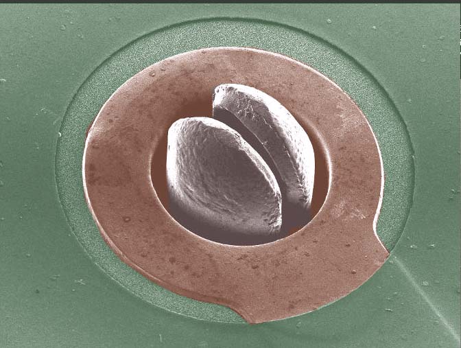
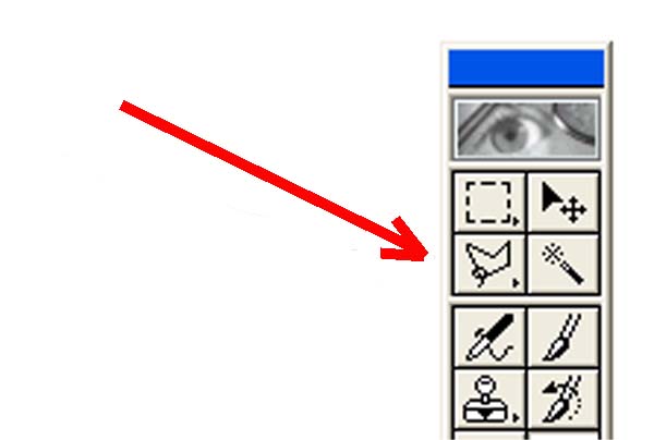
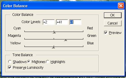
The above colorized image was created in Photoshop 5.0 by selecting (lassoing) the area to be colored and then Image/Adjust/Color Balance and using the sliders to color only the selected area. Then selecting or lassoing another area and coloriung that portion of the image in a different color. The colorization gives the image a pastel-like look that is very typical of colorized old films. The colorization is non-destructive as merely using the Photoshoop "Desaturate" function removes the colorization and restores the original B&W shades of grey/gray - however you spell it. This process can be used to highlight key areas of the image or to give the image the proper colors - as if we were viewing the object in sunlight rather than B&W color-less electrons.
In the above example - it shows a green circuitboard with a copper trace and a shiny silver-color component sticking out the through-hole. The colorization of the copper-color and green circuit board make it more realistic - but still gives it that surreal SEM microscope look - which I like alot. So we took a SEM Backscattered Detector image and from that created a colorized fake SEM Secondary Emissions Detector created image.
Comparing the before and after results is quite remarkable, and the image is much clearer and easier to view and understand. It is important to note/mention that the image was modified in Photoshop so the viewer knows. Photoshop is often used - without anyone mentioning - that it was used. Showing both the original and the Photoshopped image can go a long way to satisfy those that need enhanced images and those that like original unmodified images. Providing both - is always a good idea and adds to the credibility of the image rather than detracting from it.
I should also point out that Photoshop 5.0 also has the ability to adjust the saturation level. The colorized pastel-look can be made milder or more exaggerated by using the Image/Adjust/Hue Saturation slider left-or-right. Also brightness and contrast and other functions help bringout details in the image.
I would like to find a new or used 14-pin Photomultipler tube
(Any of the following would work)
A. Hamamatsu R268
B. Burle S83068E (Exact substitute for R268)
C. Hamamatsu R6095 (recommended by an online website vendor as a replacement but wrote not quite as rugged as the original R268 - whatever that means. That website said that Hamamatsu discontinued the R268 and the mfg recommends R6095 as the replacement - I dont know if that is correct. Can someone confirm or refute that?)
D. Various brands 9524B
E. Various brands 9924B (different number of dynodes than R268)
F. Thats is all I can find - if you know of another substitute - let me know
Update 2/3/14 I received an anonymous response to my Craigslist ad looking for ISI SEM parts and the message said, "Fyi, I believe that a Thorn EMI Model# 9924A will substitute for the r-268 that you need." I dont know the sender and I cannot verify if this is a fact or a hunch on the sender's parts - can anyone confirm or refute this?

|
Burle S83068E direct replce for R268 Data sheet.pdf Size : 349.037 Kb Type : pdf |
2/23/2014
I am putting forth effort to buy 2 things - a Hamamatsu R268 used PMT tube from an ISI SMS2 and a flip open cover from an ISI SS40 (slightly too long but I am hoping to modify it to work). This week was dismal for me saleswise as the cold winter weather (An extra few weeks of winter and extreme cold conditions - Polar Artic Vortex) probably depleted most people of their paycheck as utility bills were astronomical (Mine too). Also the Olympic Winter games and Superbowl drew large viewing television audiences (watching TV reduced online browsing) and having all three events all in the same short period of time - affected my online sales. I am hoping that the end of the month will bring in some needed sales - so I can make these 2 purchases. These 2 vendors of used ISI parts have been very kind in granting me a small grace period - and they wont hold out forever so I hope I wont miss this opportunity to obtain these 2 parts.
Ironically I'm fixing a formerly half-million dollar machine and having trouble coming up with a few bucks to buy scavenged parts. LOL.
The wood to build the ramp costed more than the microscope purchase price. Aint that something. And these small replacement parts cost more than the wood. But I'm not complaining. Ill find a way.
The above picture shows the used Hamamatsu R268 tube and detector I purchased.
2/28/14
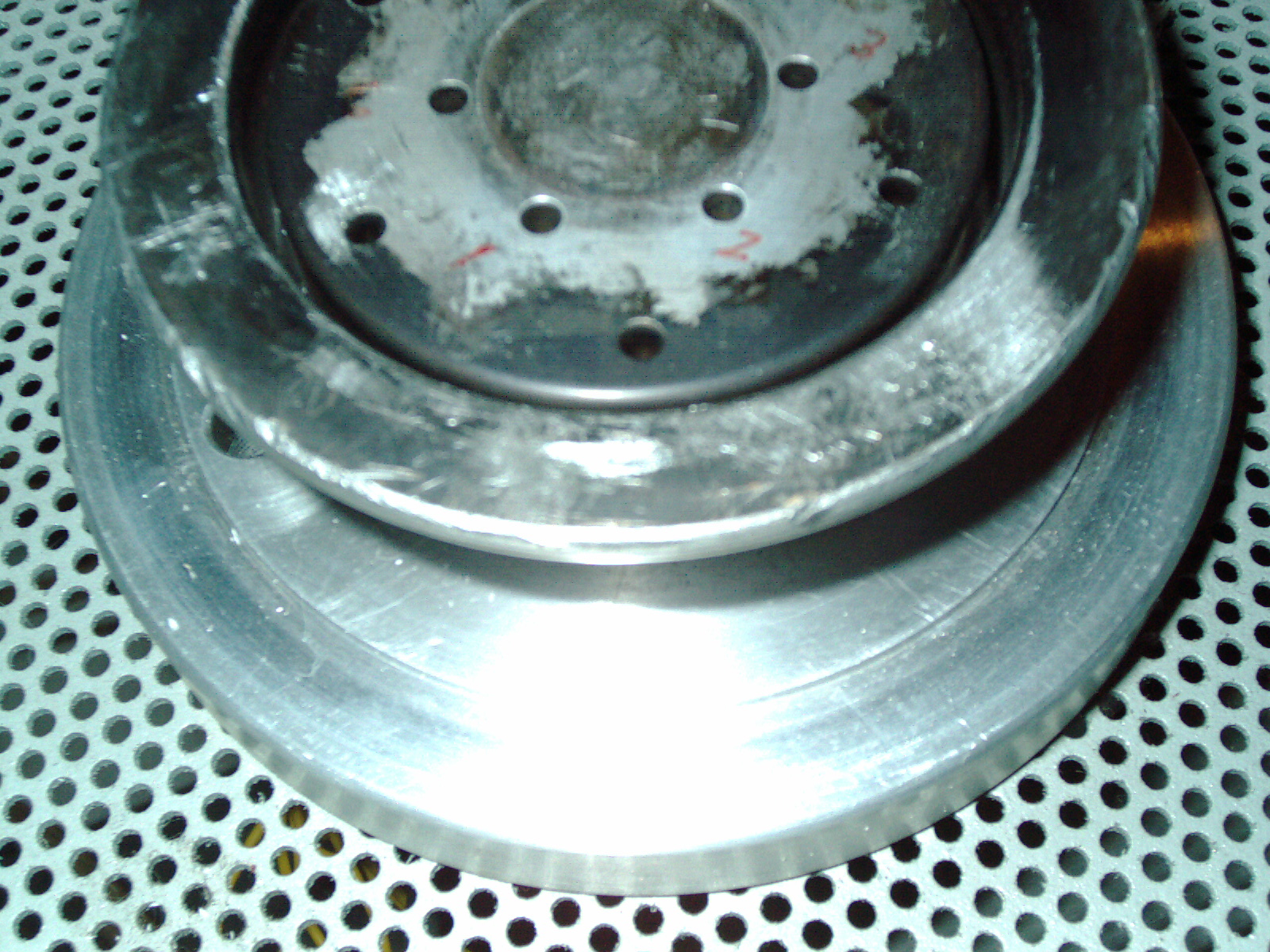
I received the Hamamatsu R268 tube (which was part of a detector) which I purchased on big-auction-site for $100 plus shipping. This detector is from a SEM microscope being parted out by the seller. The other parts I saw for sale from that seller - were very very rusty and I'm so glad that the pins of the tube are not rusty at all. The tube and tube socket are nice and clean and the tube was not rusted in place or anything. The tube looks nice and clean and the only flaw I see visually is that there is a circular scratch on the sensor end of the tube- probably caused by someone breaking off the detector from the very same plastic disc. The very same black plastic disc was broken and the previous owner was fortunate that the tube didnt get cracked. At this time I feel that I have a potentially working PMT Photomultiplier tube. I am also thinking that the circular scratch that I see may or may not be a scratch. I'm wondering if it is a calcium or lime ring or other chemical ring. I dont know at this point if it is a scatch or not. But the sensor should be able to see enough to function as the scratch is not a visual obstruction and the tube's vacuum doesnt seem to be compromised. I can tell that the tube is still holding a vacuum by the "getter" inside the tube. This getter is a chemical they put inside the tube as they are sealing the glass during the mfg process. The "getter" absorbs whatever remains of the air inside and becomes chemically bonded to the "getter" If air was introduced by cracking the tube - the "getter" would change color to white. So I know that there is no crack in the tube glass. Whether the tube is good or not remains to be seen - but I know it is holding a vacuum and visually looks good-enough.

My intention for the above 2ea photos was to show the circular scratch on the used tube I bought. The circular scratch is minor and didnt show up well no matter how many times I tried with various lighting conditions. But interestingly if I turned the camera flash on or off - that made a big difference in the translucent qualities of the sensor end of the tube. A Camera flash makes the sensor end transparent. No camera flash makes the end of the tube opaque. I am likening this effect to LCD shutter glasses or auto-darkening welding helmet (except opposite - a welding helment darkens when it sees a flash). The inside of the tube end is coated with a coating. My cracked tube does not look like this and my cracked tube has the silver side very deteriorated from within. The inrush of air had a very violent effect on the broken tube? Who knows - I am only guessing.
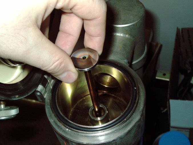
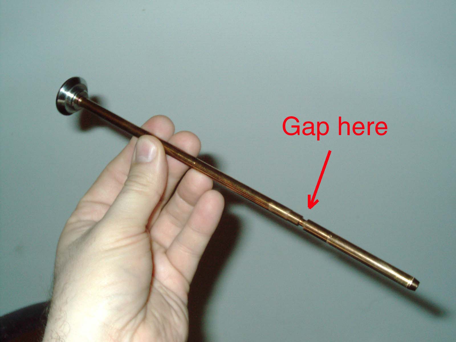
The above 2 pictures show the column liner which is made of brass. It is made of many small sections which are threaded (like how a ball point pen is disassembled) and each section contains a small insert with a tiny hole. My question is about the odd looking section above which is actually "floppy" and dangles. It reminds me of a pen assembled without the metal ring in the center. Can anyone confirm that the section shown in the above pictures is supposed to be like this? Or is something missing? I would like to buy a spare Column Liner (like pictured) if someone has one for sale.
Update 3/5/14 I received a reply from a knowledgeable vendor of ISI parts that my Column Liner is supposed to look like this. The "gap" is normal and looks like this. So I am relieved that I am not missing a piece. I am still looking for a spare column liner and more parts and books.
Update 6/11/14 I received an email from a university student looking for information on the ISI microscopes. I'm restoring this SX30 machine and acquiring parts - but I've actually never operated one or seen an SEM in person - only my own machine. My skills in repairing electronics are general so I have no doubt that I will get this machine up and running. My budget is limited so it will take quite some time to complete this machine. I still have to buy a pump (and step-down transformer) which I believe the original pump was a "Hitachi 160VP CuteVac" which is a 100 volt pump. I see other ISI Electron microscopes of various models on websites and big-auction-site which are using the Hitachi pump - so I am fairly sure that is what the machines came with - although the manuals dont mention which model it came with originally. My machine didnt come with a vacuum pump. The seller of my SEM offered a BIG BIG BIG and heavy carbon coater machine with a bult-in pump for $100 but I had to pass due to the size and weight - due to floor space and extreme weight would damage my floor (someone else bought it a short time after). My SEM was so big and heavy that it sat on my trailer for a month until I could figure out how to bring it off my trailer and into my small lab and build a ramp and pay people to help me. So that was the best I could do- especially just a couple weeks before "Polar Arctic Vortex" storm hit my area - coldest winter (-50deg F) in recorded Chicago area weather history - dating back - records kept even in the 1800s. I couldnt have done any better or worked any faster with limited resources. Even now as I write in June - its been 2-1/2 months since I purchased any parts - I'm still paying off my winter bills in installments and being hounded by utility company. $1500 utility bills for one month is hard to tackle when you have regular months bills to pay too- yikes. Even so I am juggling 3ea restorations at the same time Thermojet 3d wax printer (see my webpage for restoration) Rank Cintel restoration (see my webpage for restoration) and ISI SX30 Electron Microscope Restoration (you're reading it right now) I saw an ad for an SX30 being sold online by a SEM microscope reseller- the price was $30,000 and in working perfect condition. I could never afford that. I'm glad to have a fixer upper and worth all of the effort, expense, time it takes to restore it.
I noticed that Windows XP running Firefox 12 and Flashplayer 9 does not work anymore for the webhost I use - for uploading photos. I was going to upload a photo of the Hitachi 160VP vacuum pump but I am forced to upgrade software. Dont you hate that? I purchased Windows Vista 2 weeks ago ($10 approx from big-auction-site and came with a memorystick 128MB) and will need to buy an IDE hard drive (I learned a long time ago to install a removeble HDD for each version of Windows so I can just swap back and forth between OS by just exchanging the HDD cartridge) and install that sometime. One step forward and 2 steps back ... Once I have Vista up and running (have to buy a HDD first) - then I think the later version flashplayer downloads will load fine. But text functions work fine. This webhost doesnt offer ftp (old school way of uploading files) and relies on manually upload my files as I build my webpages manually as I go.
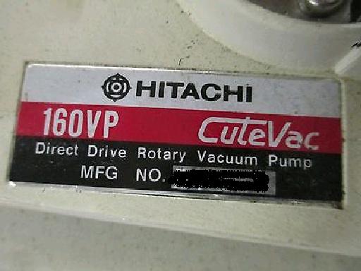
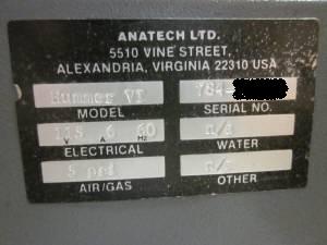
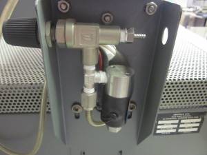
Update 6/18/14 I see that my website host has fixed the upload issue which has plagued the hostsite for months. Today it worked very well; And so, I uploaded a photo above - which shows the nameplate of the Hitachi Vacuum Pump which I suspect is the original model. I could be mistaken; But, it my hunch that it is what the SEM came with. I don't yet have a vacuum pump.
Update 7/29/14 A phone call from ISI SX-30 owner confirms that his microscope purchased 1 year ago came with the Hitachi CuteVac 160VP and he said there is no voltage input sticker on his unit - so the input voltage of this pump is not known. I believe it is a 100V pump and requires a step down transformer to operate in USA or overheating or premature failure is a possibility. It is not clear whether the transformer is intended to power the pump and SEM microscope simultaneously.
I am still looking for an ISI Transformer (beige rectangle metal box weighs 75lbs approx) -
Let me know if you have one for sale.
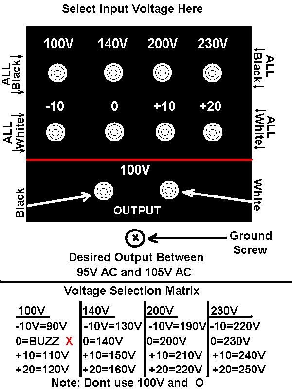
Update 7/29/14 I have added this photo after having a conversation by telephone with a 1year owner of a ISI SX-30 and hoping that an exchange of information will take place that is mutually beneficial (he has more manuals and has a more complete system than mine at the present time) the callers concern was that he does not have the correct input voltage to run his machine. The above picture is one in which I show how the transformer is sett-able to various input voltages. Also by using the -10V or Zero or +10V or +20V you have fine tune the input of either 100V or 140V. I dont have a transformer and have never tried this so this is my professional "hunch" and it makes sense that it would work - but I have never tried it. I have been looking for a transformer and found one on ebay but price is out of reach - so soon after Polar Artic Vortex record breaking winter and I am still paying off my utility bills - so this big-auction-site transfomer is out of reach financially right now. I asked the caller if his transformer has a cover over these wires and terminals and he said that there are 4 screws on a cover plate which needs to be removed to expose this settable terminal area for various input voltages. Please note that the ISI SX30 microscope runs on 100Volts AC. Do not attempt to run it on household power which is at least 20+ volts too high. You must use a transformer. I feel that setting the transformer to 130Volts AC input and output of 100V is "close enough" to work properly. I also noticed that my household outlets provide somewhere between 123v and 126.5 volts depending on time of day and seasonal use. This recent voltage climb in my ac outlets is due to a change in USA power and is common throughout the USA. Some areas of USA are still running at 115volts or 117volts (my area was 117V until a few months ago when a electrical transformer tower construction / road construction commenced). My area was one of the last areas to change. This 126.5Volts AC coming out of my outlet means that many of my appliances and technical gear is receiving too much power and a step down transformer is a must (such as a Variac). I hope that the caller will help me by providing a photocopy of the manual and schematics. He tells me that he has a complete schematic diagram of the entire SX-30 in his manual and is on several fold-out "centerfold" pages. I hope that I can acquire those badly needed schematics.
A third input voltage option - not pictured (I created this photo using PAINT software 7/29/14)
There is also a +20 volt terminal so that gives a third input voltage option which is 100V plus 20volts = 120Volts which would also be "close enough" but since the actual voltage fluctuation in my AC outlets can go to as much as 126.5 volts - I think having it set to 130V input is better - but that is just my hunch. It is best to take a reading with an accurate multimeter and see what the transformer actually provides at each setting. The real world and book-learning are not always the same. Thats where a voltage meter would come in handy and what I recommend for the reader - take a reading of your transformer before actually hooking it up to your microscope. If you blow your microscope it is your fault not mine. Setting it incorrectly is a matter of your own voltage in your area as power throughout the USA is not standardized- and they change it without notifying you. Imagine that! The SX-30E manual states that the microscope requires 1700watts - it is not clear whether that is with or without the vacuum pump running - no mention of which pump etc in found in the manual. The caller has the SX-30 original manual so that would help alot to have the correct manual rather than one that is a fairly close model.
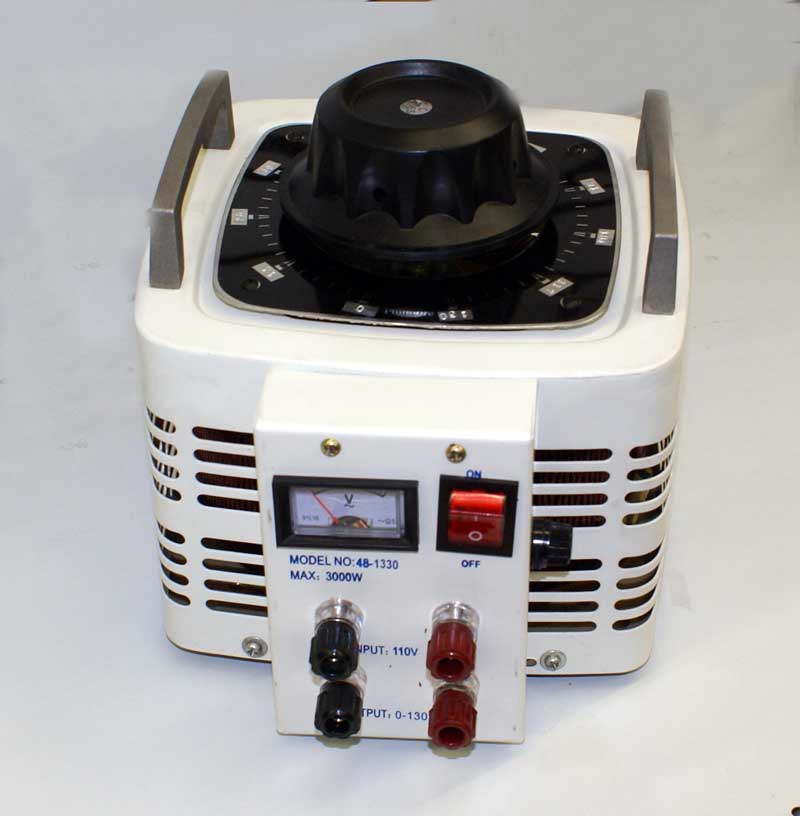
Please note that a Variac Variable ac transformer is also an option where the output voltage is infinitely adjustable and is a more precise way of obtaining the correct output power. But the high amperage and wattage of the microscope and pump means that the transformer needs to be heavy duty. I like the ISI transformer as it is beefy and robust. The only disadvantage is the "close enough" voltages that are selectable in only 10v increments - versus the Variac where it can be set precisely to the correct voltage. Of course - dont accidently set the Variacs knob too high or too low or "magic smoke" will be released from your microscope electronics and will cause your SEM to die. I like the transformer and I want to buy it - but I dont have the funds right now. If it is purchased before I acquire the funds - I may have to go with a Variac as they are common to find on big-auction-site new and used in the 2000watt or 3000watt range.
I have created the above drawing which shows the terminals for ISI step down transformer included with many models of 1980s SEM microscopes. Note that having an input of 100V and an output of 100V makes absolutely NO Sense and this transformer does not accept it.
WE ARE SETTING THE INPUT VOLTAGE NOT THE OUTPUT VOLTAGE THE 100V OUTPUT IS A GIVEN
When they should instead set to (for example) 100V +20 OR 140V -10V
I HAVE DONE MY BEST TO EXPLAIN THIS - DONT THROW IT OUT. DONT WASTE THE ISI SEM OR TRANSFORMER.
Also, I have noticed that the printed numbers such as 100V and -10V may not be accurate - so always check the output using a multimeter before actually powering on your SEM. (for example providing 119V actual input setting the transformer to 90V - gives an output of 107V but in theory should stepping up not down- see what I mean) So there is a bit of trial and error in getting the settings right (but not while connected to SEM)
I suspect that when I actually receive a transformer, if I create a real-world matrix with input voltages versus output voltages - then there would be some variations. Such is the difference between "classroom learning" and hands-on experience and even so I am without any manual in this transformer settings.
|
|
ISI Transformer Matrix Full Opposite Alternative.JPG Size : 86.907 Kb Type : JPG |

|
ISI transformer Extra Information 011217.txt Size : 3.141 Kb Type : txt |
|
|
ISI Wrong Test 107VAC Out 119VAC In.zip Size : 659.15 Kb Type : zip |
|
|
3000watt Variac.jpg Size : 36.845 Kb Type : jpg |
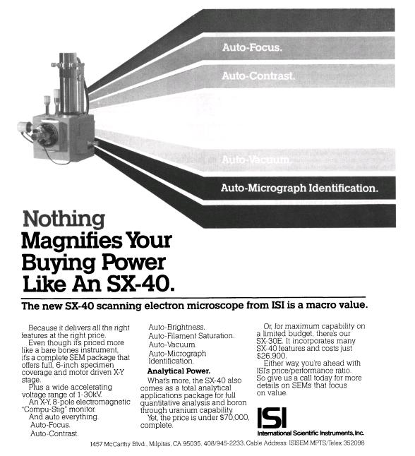
My SEM is a ISI SX-30 and predates this ad by one or more years. My column looks different and taller than the ad. I hope that's a good thing.
Update 12/3/14
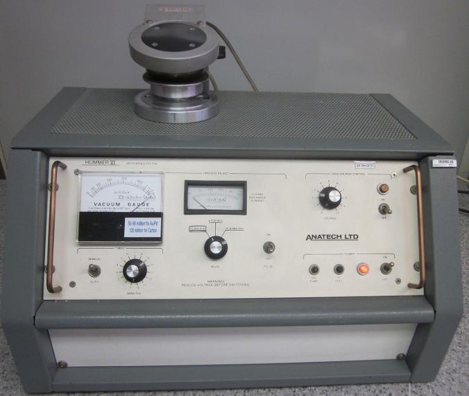
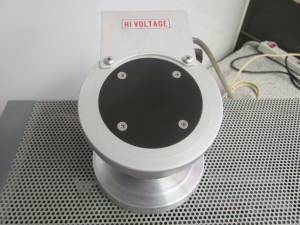
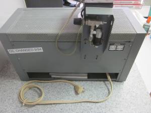
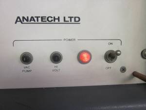
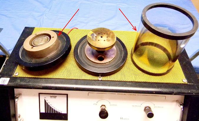
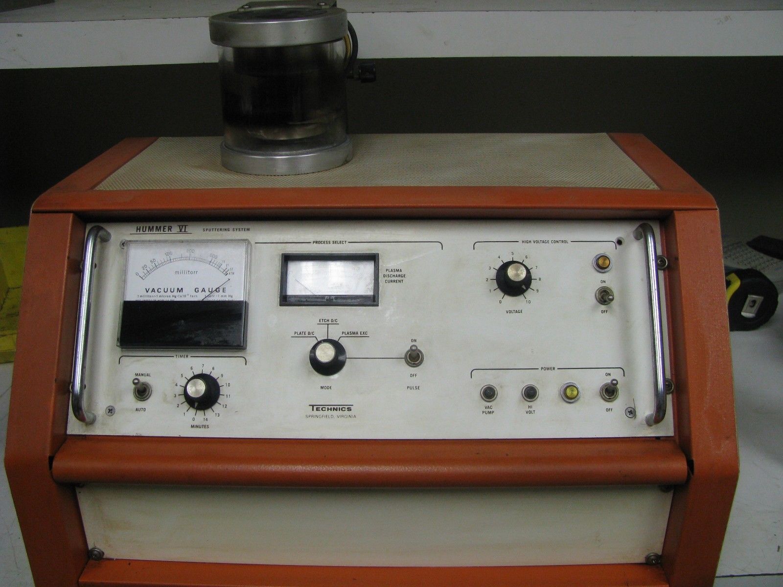
I purchased a Anatech Hummer VI Sputter Coater on big-auction-site. It is decribed as having a working pump. It is at least 20years old as I see a sticker on the unit which states that the oil was changed in 1994 LOL.
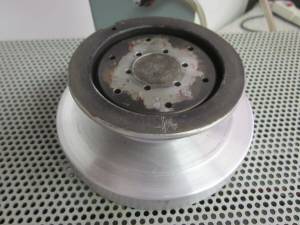
I know it is missing the glass Pyrex (Borosilicate Glass Tempered) and the source disc and holder ("magnatron" or "magnetron"). Sometimes things sit
in my lab waiting on a part or piece which I find later on big-auction-site or sourced from a reader. The
description says that the pump is working and pulls a vacuum. I read
from the downloaded online PDF manual that the interlock wont work without the glass and
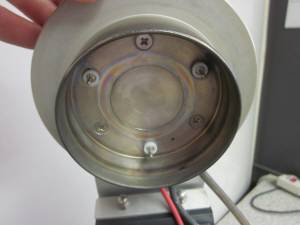
without a vacuum. The sputter coater looks to be in good shape. People pull out the source
disc (gold or other metal) before they sell sputter coaters - I see that quite often in my search for a used sputter coater. Its not the source
disc which is precious to me - it is the souce disc holder ( "magnetron" ) which is more
important to me - that is missing too - I only see three ea banana plugs
in the photos - that is where the source disc holder "magnetron" goes.
The
actual gold usually found on these source disc holders is very very thin and the high
price the vendors put on the gold is ridiculous. a 2" dia gold disc with a
thinckness of a piece of paper .004" is $1300. Ebay has gold leaf 24K foil for $1
and is a similar thickness. That can be applied with silver bearing
conductive epoxy. That is is same way the replacement gold discs are
mounted. The sellers of gold discs are raking in the pofits. The only thing I need to be careful about is which gold foil or gold leaf - it is usually coated with wax - so the gold leaf that I find will need to be wax-free. Other metals can also be used like silver or copper.
I
will need to find a glass "Pyrex chamber" and also the source disc holder "magnetron"
The Anatech Hummer VI has a built-in pump which is what I was looking for - something with a pump.
The
school teacher who sold me my ISI SX30 microscope wanted to sell me an enormpous carbon coater for $100 - and I passed
on it because the sheer size/weight of it exceeded my available space. So I feel that I have found
something better now - even though I will need to source replacement
parts or improvise. This is a much better way to do things (for me and for my applications and space requirement) - with a
smaller multifunction sputter coater.
I need to find
A 4" Dia Pyrex Tube (this is an inner diameter and could be greater than 4")
B 2ea Rubber seals for the above Pyrex Tube (I dont have a Pyrex Tube - I seek this) sometimes called L-gasket duy to its shape (pretending as if cross-section view - but it is a continuous ring)
C (Source Disc Holder) "magnetron" or "magnatron" or "target" or "annular ring" etc
Let me kow if you have Anatech Hummer Parts - I think this Pyrex tube and rubber seals and source disc holder "magnetron" is applicable to several models of Anatech sputter coater - let me know if you have used parts for sale.
Also I see some other brands like SPI which have models which use a 4"dia Pyrex glass - let me know if you have 4" dia Pyrex glass from any brand sputter coater (or other application) as I may be able to adapt it to work.
Sometimes high heat OTHER items - like street lights, gas mantle lanterns, custom length tubing etc other scientific applications may be a source for these Pyrex 4" dia tube. It needs to be a pretty hefty wall thickness - let me know what you have. I may be able to cut it to length?
This sputtering technology is sometimes referred to as "DC Magnetron Planar Sputtering"
(The sputter has a mode switch for etching and more - but at this time - my only need is sputtering SEM samples)
|
|
Technics Hummer Jr on big-auction-site.JPG Size : 135.14 Kb Type : JPG |
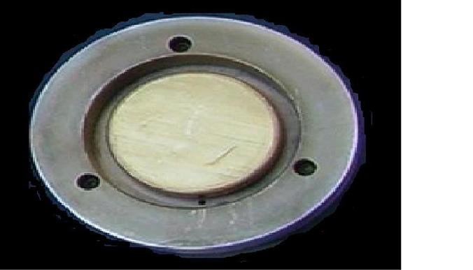
I can obtain my own gold from big-auction-site and adhere it with silver bearing conductive epoxy. You can keep the gold and peel it off - if you want to (as thin as tin foil and weighs almost nothing). Let me know if you have this magnetron as pictured above. This picture is a closeup view of a Technics Hummer Jr which I think is exactly the same magnetron as I am looking for.
I dont know the exact diameter of this magnetron - but I estimate it to be about 3" diameter. The center part is approx 2" diameter.
While researching the topic of Anatech Sputter Coater "magnetron" - I have learned that it is not just one piece target holder. There are two pieces - one is an aluminum "Annular Ring" this is the part that has three holes in it and actually contacts the three each banana plugs. The aluminum annular ring looks like a "donut" and is approx 3" dia and has a hole in the center approx 2" dia. The aluminum annular ring is a target for etching (I think) and gets a target bonded to its surface - of the same material as being etched. This annular ring - is offered as a trade-in discount by some SEM parts suppliers. For example if a person buys a new Annular ring from them - and trades in their old one - then they get a small percentage off. I would like to acquire one - I plan to clean the surface and bond my own material to it. If I cant find one - then I will machine one on my lathe.
I see a demo on youtube which shows this annular ring. I am not affiliated with this youtube author. Here is the link to it - look at approx 12:20 for the part about the annular ring and how to remove it. The machine is a different model but is the very same annular disc that I need. (I also need the 2" approx dia center part - I am missing that too)
https://www.youtube.com/watch?v=QJZy3nwu4UE
Update 12/24/14
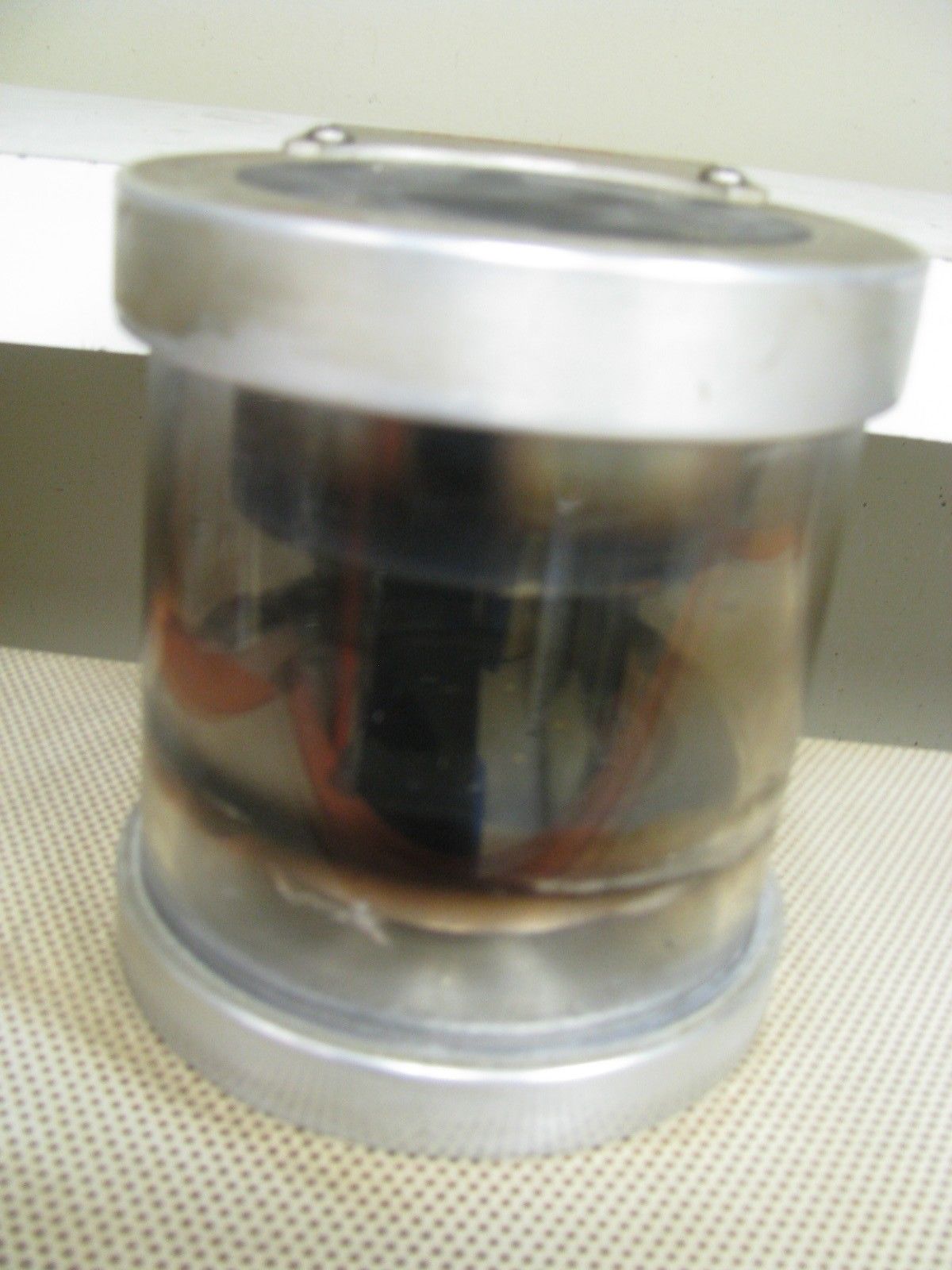
Here are a few pictures showing what I was looking to use for replacement chamber - but decided against going this route:
I see some sputtering systems on big-auction site which look identical to my own Anatech Hummer VI.
For example "Technics Hummer VI" looks identical and even bears the same model name - but differnt brand name.
I have included a few photos here in a photo gallery - click on the picture to enlarge. Also notics how thick the original Pyrex chamber is - wow that has a thick wall. I dont think the Apothecary bottle will have that thickness!!!
So the parts I need can come from a Anatech or Technics machine. If I cant find the parts - I will try to improvise. The Apothecary bottle seems to be the best improvise material I can find - at this moment.
Here is a youtube video showing a Technics Hummer II (extremely similar to the one I have even though differnt brand and model ) Demonstration
(it is not my video and not affiliated with it)
https://www.youtube.com/watch?v=E-mvUfNHOSM
I found several good sources of the rubber seal that goes above and below the Pyrex Chamber. The lucky words to search for on google or other search engine is "Buna-N (nitrile) Bell Jar Gaskets" or "L-Gasket Bell Jar" When I searched for Pyrex Chamber Seal Sputtering I didnt come up wiuth anything. I tried all combinations of searches and didnt find anything until I used the lucky words. I even see a seller on big-auction site that sells these seals. But first things first - I need to either find a Pyrex cylinder that is the right size or make one myself. I feel better knowing I now know some sources for this gasket in various sizes. I measured my Amatech Hummer (which arrived today all busted) the diamter of the chamber must be 4" ID inside diameter of slightly larger. There is a raised "curb" or bump on the metal plate that it sits on - and that forces the diameter to be 4" or greater for the inside diameter. there is quite a bit of leeway for the wall thickness. I'm thinking it could be drastically greater than 4" inside diameter. I measured my pickle jar and maybe it is too small anyways.
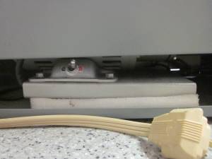
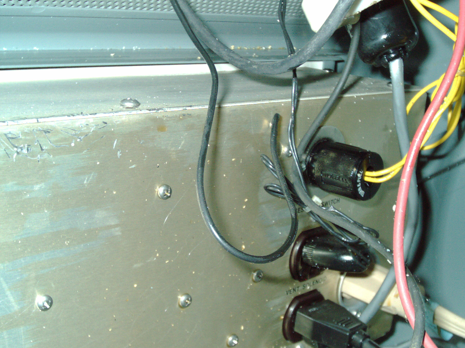
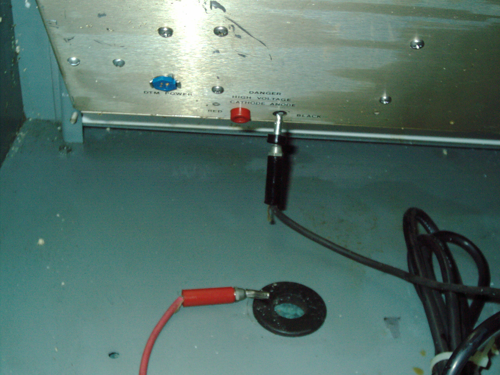
Regarding my Anatech Hummer VI that arrived today - the seller protected he outside of the machine very well (oversized box, lots of pieces of molded styrofoam - like froma TV set, and they packed it well. But they forgot one very important thing - there is a vacuum pump inside and it wasnt bolted down or secured in anyway - so as UPS rolled the box like snowball (out side of the box is round - so that makes me think it was rolled. As UPS rolled the box the vacuum pump was bumping and clanging everywhere on the INSIDE of the Sputter coater. There is a lot of damage. Oil everywhere, styrofoam bits by the thousands everywhere, broken connectors, broken vacuum gauge, bent and scratched and gouged aluminum plates. Yikes.
I spent 2 hours with a vacuum cleaner and rags trying to soak up all the oil and debris. I found some replacement gauges on big-auction-site by searching for "millitorr vacuum gauge" and I see some used ones for approx $40 maybe they work and maybe they dont - who knows. I emailed the sputter coater seller to inform them of the damage. Some sellers are helpful and some are not - I'll see what they say. The $200 I paid is insignificant compared to a new one costing $20k but still - its broken heavily and wiill need alot of TLC to make work again. Which I feel confident that I can get running well. But that will cost additional money to obtain repair parts. Thank goodness for big-auction site - I will just need to hunt for replacement parts for awhile. It is amazing what you find there if you search for it diligently. I'm surprised to find my sputter coater for $99 plus hefty shipping. It is unfortunate it arrived broken. But it is not beyond repair. A brand new on is $20,000 which is way out of ly league pricewise. Used ones with problems are $2,000. Even so my $99 sputter coater is fixable - it wasnt broken when it was at the sellers warehouse- it was damaged by careless packing. I even rushed to the UPS truck when I heard it arrive - so the driver doesnt drop it or roll it. I carried it 40ft and it has a sticker that it weighs over 70 pounds. I didnt want the driver to grab it off the truck and drop it on the ground. I tried to avoid breakage by grabbing myself and carefully caryying it. But the damage was done enroute - and there was no saving it.
Summary of what is broken/bent damaged
1. Oil dumped all over - pump is empty of oil
2. 2ea banana jacks (red and black) and plugs (red and black) busted and bent
3. Aluminum sheet metal gouged and dented in
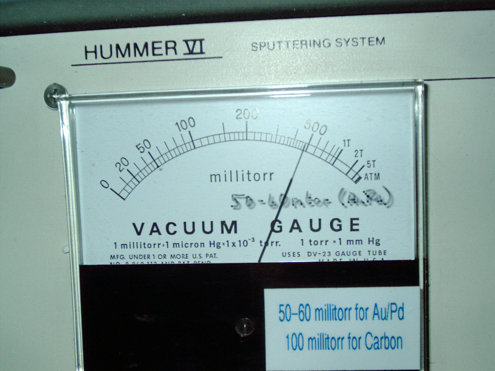
4. Vacuum gauge moves when you swipe your finger across the plastic bezel faceplate - analog gauge moves to random points when you tap on the faceplate or swipe finger across- I would say this is caused by static charge?? The gauge shouldnt move like that- its broken
5. Metal ring plate which is the sample holder - that is really gouged up and deep gouges like it was dragged across a parking pavement
6. Metal perforated cover has a bent corner
7. Probably more damage than visible - I have not attemped to power-on anything
Also I see there are threaded holes in the sample plate area - probably where some endcaps or vacuum filters go - but those were removed by the seller??
Here is what the L-gaskets look like which I need to buy.

I observed the youtube video (not mine and I'm not affiliated with it)
https://www.youtube.com/watch?v=E-mvUfNHOSM
This video shows a Technics Hummer II which is a very very similar unit - my hunch is it probably has an identical vacuum pump inside. The video shows pumping down from everyday Atmosphere pressure down to vacuum of 100 millitorr and then down to 50 millitorr and then even below.
I timed the number of seconds to pump-down
Atmosphere to 100 millitorr = 10 seconds
Atmosphere to 50 millitorr = 35 seconds
The Pyrex jar shown in the video has a crack in it clearly visible at 0min : 21sec but I'm making an assumption that the crack doesnt impede the pump down. Another assumption is the internal vacuum pump is the same.
My thoughts are that even with a non-working vacuum gauge - it is still possible to manually pump down to proper vacuum by using a stopwatch. The purpose of the pump down to create a vacuum - is only so argon is drawn in to the chamber in the hopes of completely removing air as much as possible. The end result is a Pyrex cylinder which contains argon and is not a full vacuum at all. This purging process of vacuum-then-fill-with-argon is repeated several times in the goal of having pure argon in there without any air - but it just gets you close - but never will get rid of all the air - only minimizes it. Fom what I have read - It is not critical to get out every molecule of air (whether that is correct or not I dont know). I'm sure at molecular level - high quality sputter coating is very important for viewing at high magnifications.
If too high a percentage air remains in the chamber while sputtering - then the coating will be black and sooty oxidized/rusted in appearance. The goal is to have a shiny metal plating of the metal (gold, copper, aluminum, etc) target material. Some trial-and-error is required to figure out how many times to purge the chamber with vacuum-then-argon cycles to give coatings the desired shiny metal appearance. Once I get good results - I will then know how many vaccum-purge cycles it takes.
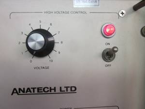
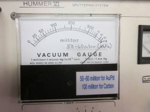
I see a sticker and notes written on my unit from the previous owner (see photo)
"50-60 millitorr for Au/PD" (I think this stands for Gold Palladium targets which are the most expensive)
"100 millitorr for Carbon"
I dont foresee any need to carbon coat - I passed on that big unit which the seller of my SEM wanted to sell me for $100. I didnt want it as it was huge and I have no use for it and I dont foresee any use for it - for my lab use. Ideally I would like to metal coat objects to be viewed in SEM to increase clarity and sharpness and brightness due to increased conductivity of the metal sputtered object. And most importantly - sputtered objects can be viewed at a higher magnification level in an SEM. My goal is to get to the guaranteed minimum 70 Angstrom maximum that the owners manual states. One comment on the internet puts this microscope at the 60 Angstrom level. I think this Hummer sputter coater is just what I needed. I'm glad to have it.
Update 1/22/15
I contacted Anatech mfg by email requesting quote on replacement parts. I received a pricelist attachment response the same day. I am seriously considering on buying a genuine replacement Chamber for it. I researched online for jerry-rig solutions but viewing a youtube video scared me - when I saw someone homemade canning jar explode under vaccum and plasma arc.
heres the video that scared me about imploding standard glass canning jar
(I'm not affiliated with this video)
https://www.youtube.com/watch?v=bPRmsDx0oYo
So after viewing the above DIY-ers imploded unsafe jar - I am seriously considering to just plunk down the money to buy the real thing - and not have to worry about glass pieces flying at me. Heres the price and parts breakdown that I will need to buy from the mfg.
A. a set of 2ea Gaskets for Pyrex Tube (Anatech part number 1007097 "Chamber Gasket Set - Viton" $60)
B. 1ea Pyrex Glass Cylinder (Anatech part number 1005003 "Chamber 4.5OD x 3.7LG" $130)
They have a $100 minimum order and I was quoted $25 for shipping for just the gasket so it may be more for all of the above.
C. I need more parts but that will suffice for now.
I will also contact international vendors of glass tubes to see what the price is for borosilicate tube. I have purchased a couple of things from aliexpress website and they have alof glass vendors there. Maybe I'll be surprised by their quote either low or high - who knows?

I was looking through my video cameras and lenses and smoke alarms trying to find something that could test my geiger counter. I didnt find anything that would be considered radioactive or hazardous. All I could find is 1 item that clearly shows the geiger counter is working. This item is a 15year old smoke alarm "First Alert" which was retired because it would only use a battery for 3 months and then start beeping requiring a new battery more than typical. I bought replacement units at a department store and they werent much better requiring a new battery at 5-6 months. But anyhow - I still have that old First Alert smoke alarm and when I put the geiger counter on it in various positions trying to elicit a response on the geiger - I can play around with where I place it and can get readings from .22-.36 I was only able to get .36 once and .28 once. the typical number is .22-.26 But this clearly shows the geiger counter does work. And those numbers are approx what other people show on youtube videos. I'm gonna say that this smoke alarm gives somewhere between .22uSv/h and .36uSv/h and that my typical background radiation is somwhere between .08uSv/h and .14uSv/h which is extremely low and actually much lower background than some videos I see on youtube. I feel that I have tested my Bella geiger counter and got some normal readings and I feel confident that it is working correctly. I'm not going to buy any thoriated gas mantle for my lantern - when I do buy a replacement lantern mantle - it will be the non-radioactive current mantles available at department stores. I dont want radiation exposure. I want to avoid it.
Update 1/25/15
Wjhile snowing at 5:30PM I placed my geiger counter in a ziplock bag and then placed it on top of fresh snow in my driveway, under the gutter drain spout, and in my yard always on top of fresh snow. I saw counter per minute betwee 4 and 11 counts so that is definitely not radioactive. My Bella geiger counter only measures Beta and Gamma. It does not measure alpha particles. I was expecting to see much higher counts when I placed it on fresh snow (as per youtube videos - which shows a major amount of radiation in snow) but I saw only normal background radiation - no elevated counts or any other indication of anything radioactive in midwest Illinois. I can only speculate that those youtubers have radon gas coming out of the ground??? Or possibly their geiger counter is contaminated. Who knows. I didnt see any such thing when I measured. Which is a good thing. Im glad there is no radiation around here.
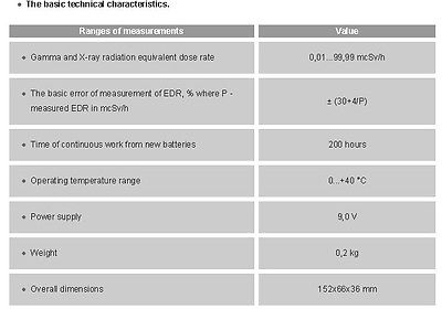
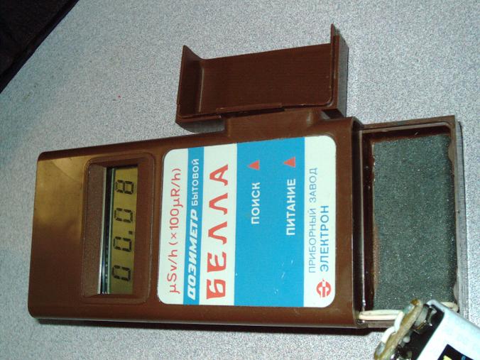
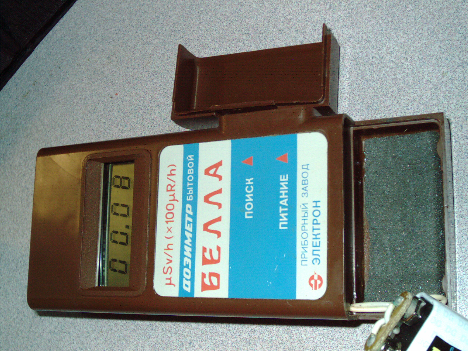
Here is the (non-English) user manual for this geiger counter made approx 1989
Does anyone have the English version manual?
|
|
Bella.pdf Size : 928.26 Kb Type : pdf |
Update 1/2/14
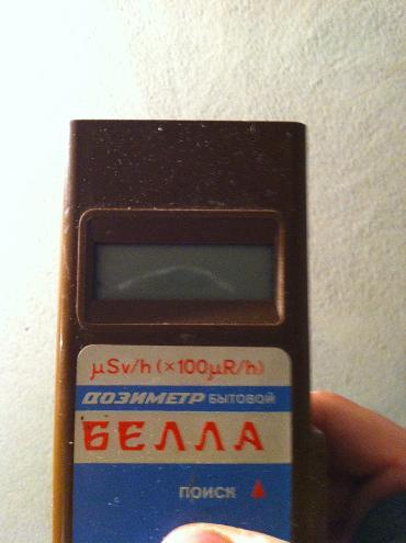
I have been searching on big-auction-site for many months for a geiger counter and finally made a purchase for a non-functional unit from Ukraine. The photos show the case frontside/backside to be in good condition and battery cover is present. The LCD looks good with no cracks or black smudges - so it apears to be a good candidate for repair.
I have been thinking about sputtering systems and SEM microscopes and tried searching for any documentation or studes regarding xrays, gamma rays, alpha rays, beta rays being emitted from this equipment. I have seen documents from universities stating that this equipment doesnt emit any of these rays. I will fix my geiger counter when it arrives so I can verify my own equipment when it is repaired.
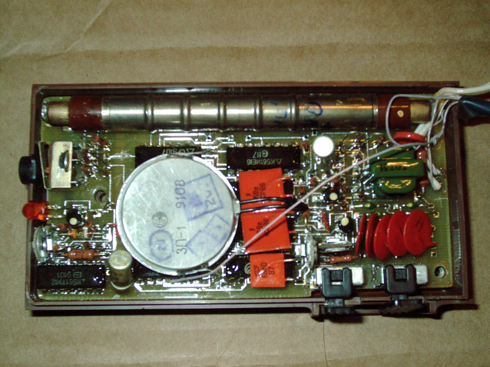
I am glad to find one at a rock bottom price of $10 plus shipping. It is a basic model without frills but I think it will perform the tests I need. The internal sensor tube is SBM-20 which is able to test many types of rays.
Here is some youtube videos (not my videos and I'm not affiliated with it) demonstrating this model Bella (or Benna or Bevva or Genna or Gella - who knows???) or similar model. Some descriptions on the videos state that this geiger counter is for gamma ray testing only. Some other rays dont penetrate the plastic case. I'm particularly interested in xrays and this SBM-20 sensor tube can detect xray particles - and xrays definitely (if present) can penetrate plastic. I think once repaired this unit wil be fine for my needs. Who can argue with $10? I have a soldering iron and plenty of test equipment and a lifetime of aquiring and using components like transistors, resistors, capacitors, etc in small small drawers and boxes. (See my above links at the top of the page "electronic parts testing service" and you will see some of my test equipment and skills.
https://www.youtube.com/watch?v=1LVTPzr342E
https://www.youtube.com/watch?v=9AJMABOhcgI
https://www.youtube.com/watch?v=NX7zBNy7EFY
https://www.youtube.com/watch?v=bU7x7-Jb1yU
https://www.youtube.com/watch?v=eMSWRoGgnNU
https://www.youtube.com/watch?v=pIQcG4IlKK4
https://www.youtube.com/watch?v=Ky0oiB0-sCk
Heres what the make/model looks like in a different language (I dont speak/read that language) frankly I'm surprised copy/paste worked for these words
Dosimeter Bella DBG-01i DBG-01N БЕЛЛА ДБГБ-01И
It looks like a very nicely made geiger counter and has a couple of nice basic features. I look forward to getting it operational and putting it to use. I see alot of youtube videos where people treat radiation as a "toy" but it is not a toy and should be avoided and shielded from coming into contact with people/animals/plants - all living things as this type of radiation damages DNA strands within cells etc. I want to check equipment for particle emissions and if present - then repair/adjust/shield the equipment to be within specifications. According to universities - there is no such emissions from SEM and sputtering systems - but I want to be sure.
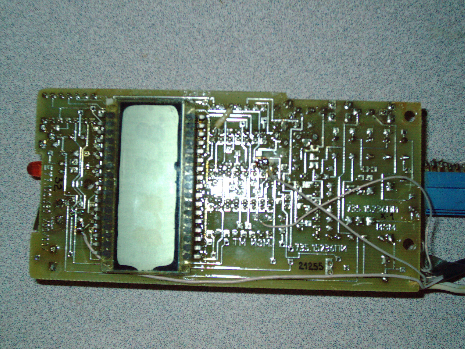
I see that the ICs have a unique symbols and numbers written in another language. I researched these numbers and I see that a few of these chips number cross reference to 5400 series TTL logic chips. Very similar to 7400 logic chips except that have a higher thermal operating range. A few websites mention that these chips differ from the standard 7400 series chips by being more radiation tolerant. I'm wondering if the cause of the geiger not working is exposure to radiation affecting the chips. I just ordered this geiger counter yesterday and have not received it. I will see if I can identify the chips. I have a few chiptesters which identify chips whether the model number is printed on them or not. Of course the chip need to work in order to be identified. I may have to unsolder them one-by-one to check them and identify them - which gives a cross reference to standard marked parts.
Most likely it is not the chips at fault as I suspect the capacitors and/or other component has gone bad - or possibly a bad connection or cold solder joint - my point is chips usually are the most reliable parts of any electronic device. It is strange that the seller is selling this geiger counter for $10 when he has SMB tubes and LCD screens for sale separately at a higher price. It might be a can of worms??? with a compilation of bad parts - who knows.
This geiger counter does not sense Alpha rays/particles or Beta rays/particles. I have read online that Alpha and Beta do not penetrate paper or other materials. These Alpha and Beta particles to the best of my research would not penetrate steel or rubber gaskets - so I dont think that the inability of the geiger counter to read Alpha and Beta rays/particles - is not a hinderance and is a non-issue. The geiger counter measures X-rays and Gamma rays - even in a limited capacity of +/- 30% would still be enough to see if a substantial amount is being emitted. My point is that this geiger counter is probably sufficient for my purpose.
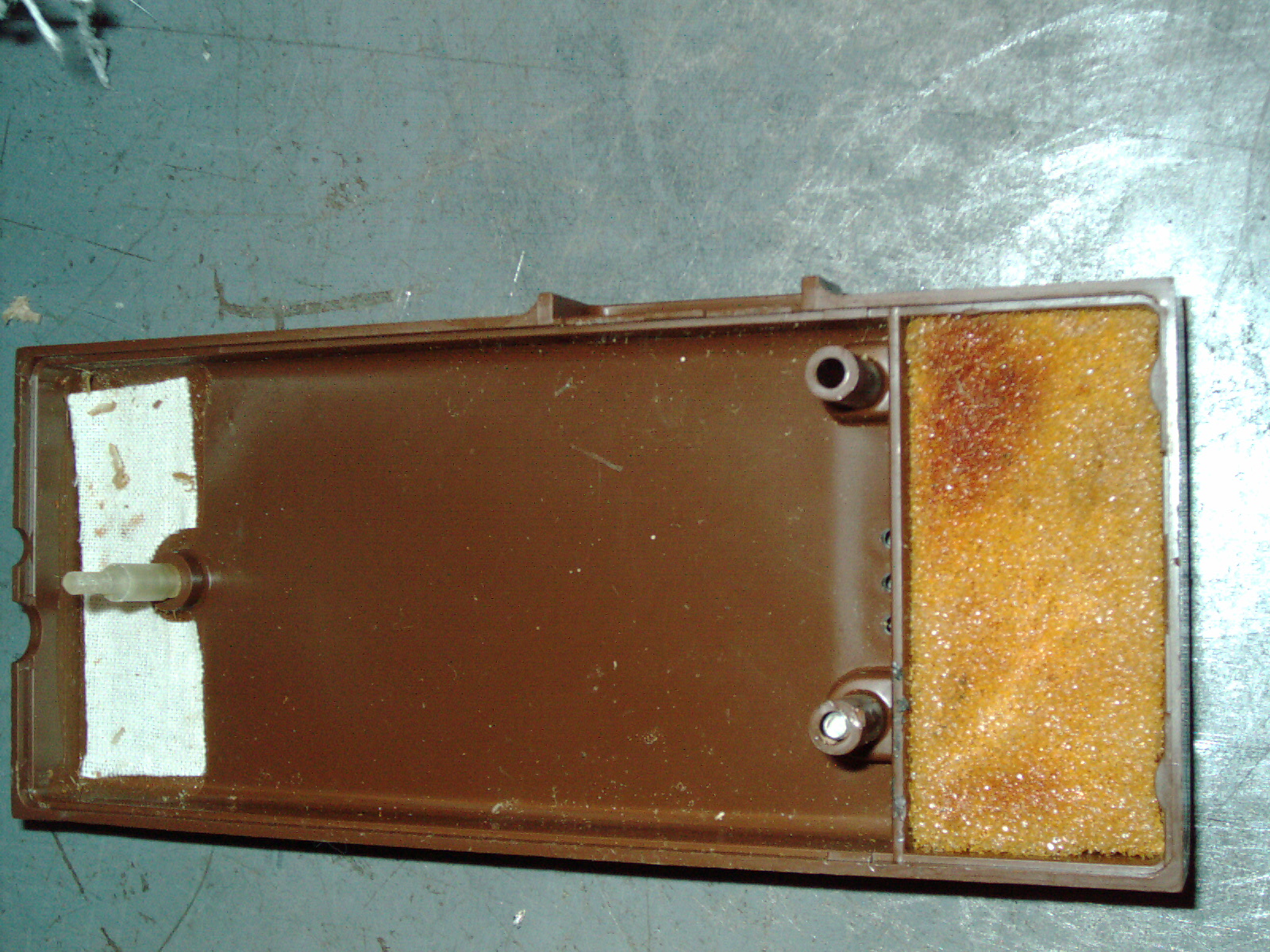
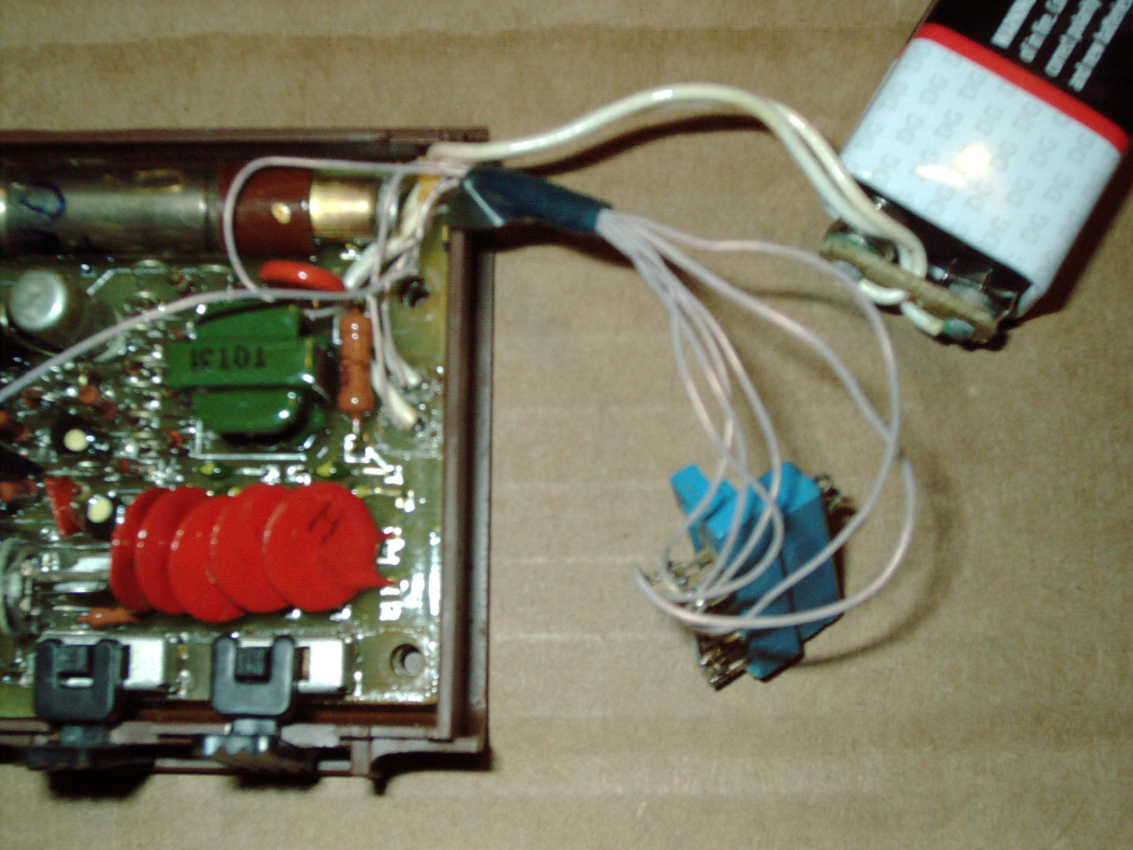
I received my Bella Geiger Counter and it was very carefully rolled in heavy cardboard several times and heavy cardboard on each end. It was a very small package and the seller knoew how to ship it. The very first thing I did was throw away the box and take it apart and clan every last bit inside and outside with Q-tips cotton swabs and green cleaner and isopropyl alcohol. Every inch of it was cleaned. It was not dirty - but I cleaned it anyways - because I dont want radiactive dust- who knows where its been - you know? Its a geiger counter - it could have been anywhere - so cleaned it VERY thoroghly.
Inside I found a homemade wiring job - I'm going to call it a KGB gieger counter LOL. Someone put a homemade connector with 6 contacts which were connected to various parts of the circuit board. Before I -un-jerry-rigged it I made a drawing. Just in case I need to put it back or maybe fine some use for it that way.
The connector has 2 jumpers and I found that if I remove 1 jumper the counter still clicks but the number on the screen stay at zero non-incrementing. If I remove the other jumper - then the display is zero and no clicks or any sign of counting. Well I didnt want something hanging off the side of the geiger counter so after I made a detailed drawing- I removed as much as I could.
I still have 2 bodge wires in there- this recreates the 2ea jumper wires that I studied the drawing I made. If these 2 connections are not made - the nothing works. So I shortened the homemade wires.
I'm going to call these 2 points
A. 1 and 16
B. 2 and 15
Hey its my drawing - I can number it however I want LOL. I looked at the connector and numbered it just like IC chip pins are numbered - then I called the point on the circuit board where it connects by that corresponding number. Maybe these points in the circuit board are for leaching a TTL: signal or possibly for a data logger - who knows? I don't need that. there are better geiger counters with that built-in. I just need a basic gener that works - not a KGB agent edition LOL.
Ok well I went around my property and belongings and even measured the vacuum cleaner bag and tool and walls and funace filter and even some times. I just didnt find anything that measures above 14 consistently. Its always different somewhere between 8-14 usually. I have a stack of tiles in my workshop - some are the same as my kitchen as spares and some are just I-dont-know-where they came from because they're all different. Anyways - if I put the geiger counter on the stack of tiles sometimes it goes to 17 soetimes as low as 10 or 12. These readings are really low and definintely not radiactive. I sat down in front of my computer and saw a reading of 8 and then later 12. And in my workshop - I checked every piece of equipment and cans on shelves of paint and gadgets and bolts and even my grinding wheels and sandpaper. I couldnt find anything that gave me anything but low readings 8-14 typically - always different - never the same reading twice.
I even took it outside and took readings on top of the snow in different parts of the yard and driveway and I got low readings of 7 - 12 always different. I even tried putting it on top of 2ea different models of smoke detectors which I took down and set a tabletop and then put the geiger counter on top. I didnt see anything but low readings again 9-14 approx.
I didnt see radioactive snow, I didnt see radiactive airfilters. I didnt see radiactive vacuum cleaner bags. i even checked the screw-on charcoal filter on my sink that filters water - even that didbnt give me anything but "background readings"
One thing that really surprised me was my prpane camping double mantle lantern. I use that regularly - it runs off a propane cylinder just like a blowtorch and it lights up the 2ea "mantles" one of which has a tear in it - but it still works so I just left it that way. It gives enough light. Well I took off the dome cover and the round protective glass and I tried to get the geiger counter to go crazy reading the 2ea mantles. It didnt react to it at all. It was just 12-14 and it wasnt going crazy like I saw on youtube videos. Mine is a used mantle - they are measureing brand new in the package mantles????? Is that the difference - or does my geiger counter need repair? I dont know.
I does seem to count and click and every function works. I fixed the 3ea things wrong with it
1. Someone didnt put the power switch on correctly so when I got it the power switch was "stuck" and I just reassembled it correctly
2. I removed bodge wires and homemade connector - I put it back as much as I could - not having anything as a reference for comparison.
3. Replaced the deteriorated foam
4. I didnt replace the 9v battery clip - that is probably how it came from the factory??
It does apear to work . it does click and give expected background counts typical of what you'd expect. My hunch is that it is working. I may buy a mantle from the store since mine is broken and needs replacing - I could replace it and before I light it -check if I get crazy readings????
The stickers are not paper and this allowed me to clean them thoroughly with isopropyl alcohol. Looks good as new. The circuit board is coated with a clear sealer. Only those areas where the previous owner jerry-rigged it have no sealer. Most of it is protected from corrosion. I cleaned off the flux from the previous owner using paint thinner and isopropyl alcohol. The circuit board looks pretty clean now. Only 2ea wires were used. The rats nest of bodge wires is gone.
An observation about this Bella Geiger Counter
I havent heard of anyone describing a Tic Tic Tic Tic Tic bzzz sound coming from their geiger counter. I notice things like that. When I put the geiger counter to my ear and listen very very closely I hear a ticking sound approx 5 tics per second- roughly 300 tics per minute- thats an estimate I havent counted the tics. The reason I havent counted is because the tics are not loud but the geiger counter BEEP every time it counts a Gamma or Xray particle is loud. I know I could turn off the volume. But I'm just saying there is a tic tic tic bzzz sound. Listen for it - you'll hear it. Its about as loud as a vintage wristwatch. My hunch is that is the SBM-20 tube doing its job. The bzz sound is not the BEEP the bzz is a soft sound and is in time with the counts on tyhe display. Of all the youtube videos and website about geiger counters - noone said naything about a tic tic tic bzzz sound. Aint that something?
Update 1/16/15
I now see why my geiger counter didnt give any readings on my Century Propane double mantle lantern. Newer than 1990 mantles are not radioactive according to a youtube author. That explains why I didnt get any readings. I'm glad they got rid of the radioactive Thorium. My light is bright enough and radioactivity is not what I want.
Here is the video showing mantles comparison. (I am not affiliated with this video. It is not mine)
https://www.youtube.com/watch?v=pOgHciym39U
Isnt it amazing what you find on big-auction-site for $10 plus shipping? LOL
Update 6/2/16
Unfortunately my Bella Geiger
Counter is not working. I wanted to use it to test a CRT inside my film
equipment which scans using a flying spot scanner - when I went to my
cabinet to get my geiger counter - it was in a ziplock bag and no 9V
battery installed. I put a fresh brand new battery in it and I see all
zeros O.O.C.O and one of the zeros is incomplete "C" due to one of the
LED segments unlit. I see no incrementing or tic tic tic. It is
unresponsive. I pressed the zeroing button on top of the unit and red
LED
lit but I see no sensing of background radiation at all. So
unfortunately I was unable to test my CRT inside my film scanner (one of
several extra parts units which I am trying to rebuild/restore/combine
into another good one) which I am currently repairing. I dont know how
it could be non-working as it has been undisturbed in the cabinet and
safely stored. I enjoyed using it and I hope to find time someday to fix
it. I used it about 12 times in the last year and was a very useful
tester. I didnt do anything to cause it to die - was just stored in a
cabinet.
Update 6/7/16
I decided to open it up and see what is wrong. I tried 2 batteries and still was stuck at O.O.C.O and I disconnected battery and tried moving the bodge wires and then reconnect battery. No change. Disconnected battery and then tried moving all of the components over just slightly - that was it a loose connection on one of the components. I reassembled after it worked. I didnt touch up any solder joints. There is a certain point of - "if it aint broke - dont fix it" Im glad that it works again- one segment of the display shows a C rather than an O but nonetheless - it is useful again. Normal background radiation differ from minute to minute but is somewhere around 7 to 13 clicks. If I put it on a stack of extra floor tiles I get a couple more clicks around 13 to 15 - so I can cell it is working normally and LCD numbers are incrementing now. The mfg coated the PCB and components with a clear coating (varnish? Clear paint?) and I dont wish to disturb that - so it works and Ill not reheat all of the solder connections.
Update 12/25/16
I tried my geiger counter yesterday and today - to read normal background radiation. The counter was stuck at 0.0.C.0. and was no incrementing or beeps. Today I decided o try and wiggle parts (to find fault) using a plastic tool and then resolder to fix this intermittant issue. I was trying to wiggle alot of parts and couldnt find anything that would get it to increment. The last thing I tried is - Doing/poke the speaker with my index finger - you know like flicking a piece of lint on your clothes. The speaker surprisingly makes a resonant sound when you doing/poke it like that- and then it started incrementing the counter. Amazingly that vibration closed whatever loose connection. So I decided to fire up the 15/30watt soldering iron and I resoldered everywhere near the speaker wires and ground wires going to the metal speaker. Including 2ea IC chips near those wires. I also resoldered the audio on/off and power on/off switches. I also resoldered the transistor closest to the reset LED. Some solder joints were stingy with solder - I redid those adding just a tad of solder.
I have been testing this geiger counter for half an hour and turning off and on - I couldnt get it to stop incrementing. That intermittant fault MAYBE solved. My LCD still has a segment which doesnt work for example 0.0.0.0. shows up as a C on one digit. So soldering some chips/transtor etc didnt solve that. But at least it increments and counts and is useful again.
I read background radiation between 8 and 13 on numerous tests. Always different each time - very normal readings.
Update 12/28/16
I tried my geiger counter just to make sure that it does work after soldering a few days ago. Still has that 0.0.C.0 pesky no counter movement and no clicks problem. I once again took it apart and got it to work by doiking the speaker and parts. This time I resoldered ALL of the solder joints for all of the reachable parts on the solderside (LCD screen side) I didnt resolder any parts on the component side - which also has solder traces etc. Im hoping whatever solder joint that was cracked/intermittant connetion got resoldered.
I played with the geiger counter for 30minutes and could not get it to error - I got normal background readings of between 6 and 13 typically. Intermittant errors are really hard to track down.
1/15/17
I have been trying the geiger counter for the past 5 days approx. It didnt startup on its own at the begin so each time I removed the case cover and tried moving some parts on the component side (speaker side) to get it to start counting. Each time I would get it to go and then the next day - tried it and same thing - stuck at 0.0.C.0 and no clicks or counter increment until I tweaked something.
Well for 2 days now after moving the vertical resistors in the 1/3 section below the speaker. And for 2 days now it starts up without having to doink or bend slightly any component. So by process or elimination - I have determined the section that has a bad solder joint. I have not resoldered on the speaker side yet. All of the joints on the other side were resoldered and had no effect.
Resoldering on the speaker side is difficult because you have to bend over the components in that cramped space. Kind of like inserting a branch in an artificial Xmas tree requires moving the other branches out of the way.
So far for 2 days I was able to get counter movement and clicks right away when powered up. So that tells me that wherever the cold solder joint is - it is leaning against the solder hole/solder pad and making contact.
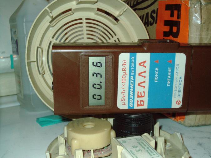
|
|
Bella Geiger COunter with KGB Mod page 1.JPG Size : 799.933 Kb Type : JPG |
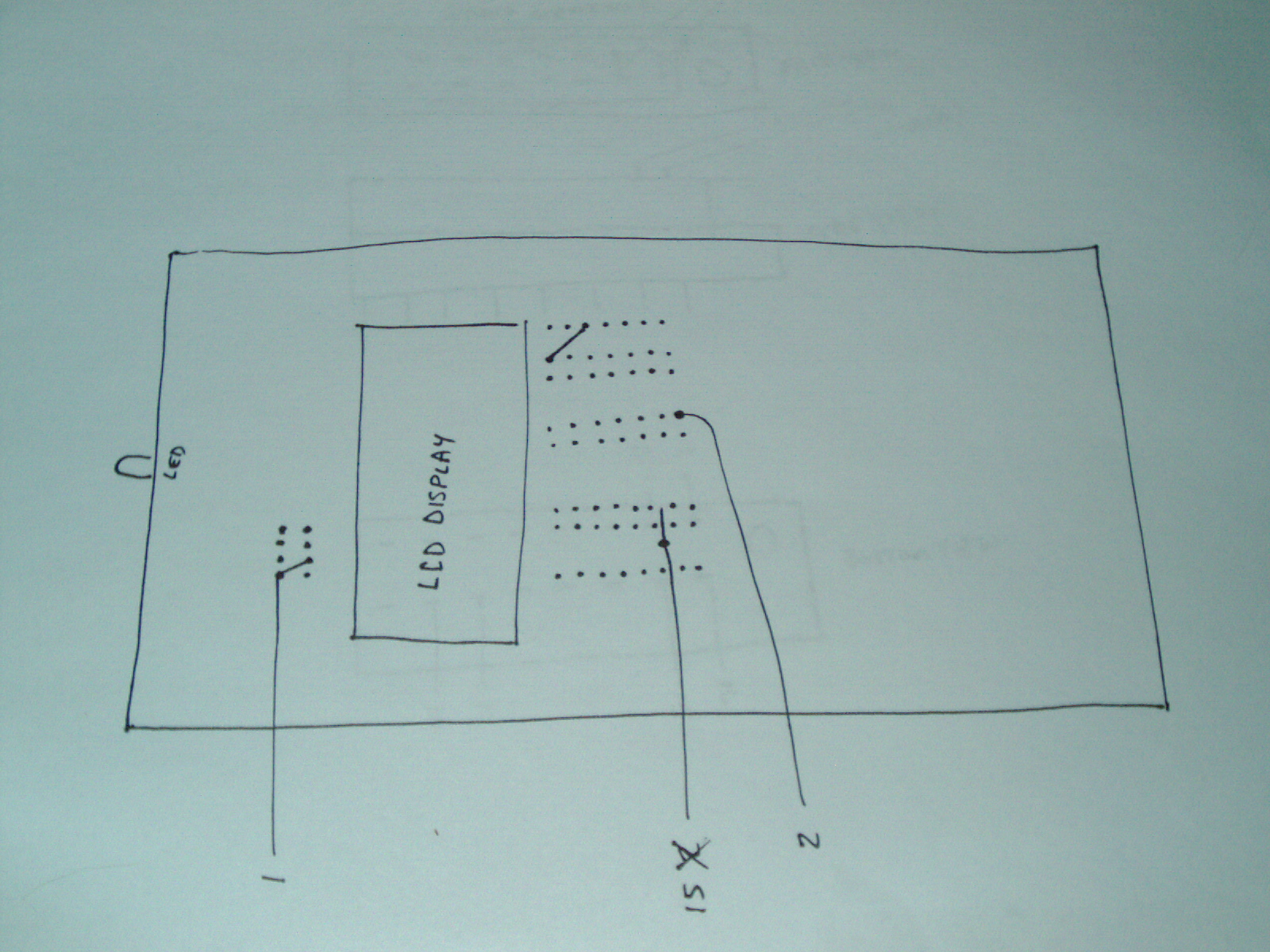
|
|
Bella Geiger Counter with KGB Mod page 2.JPG Size : 839.646 Kb Type : JPG |
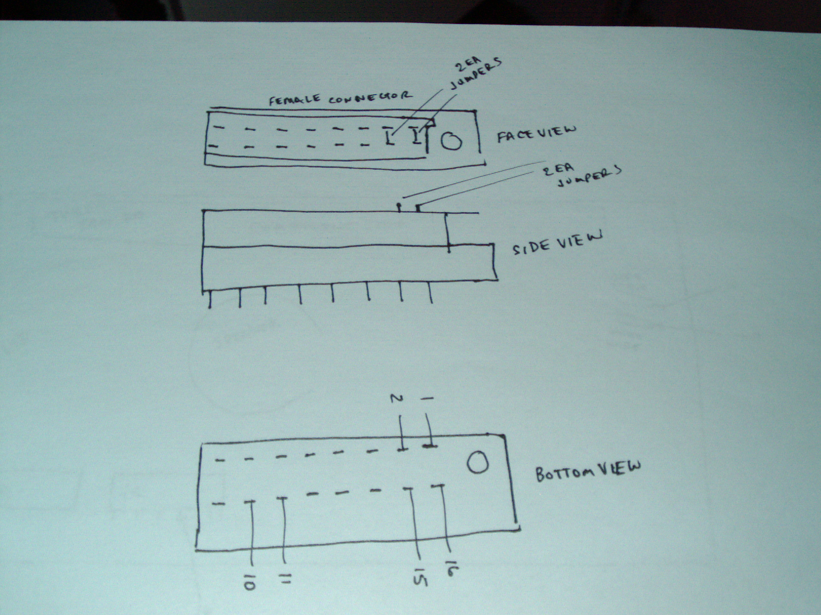
|
|
Bella Geiger Counter with KGB Mod page 3.JPG Size : 811.222 Kb Type : JPG |
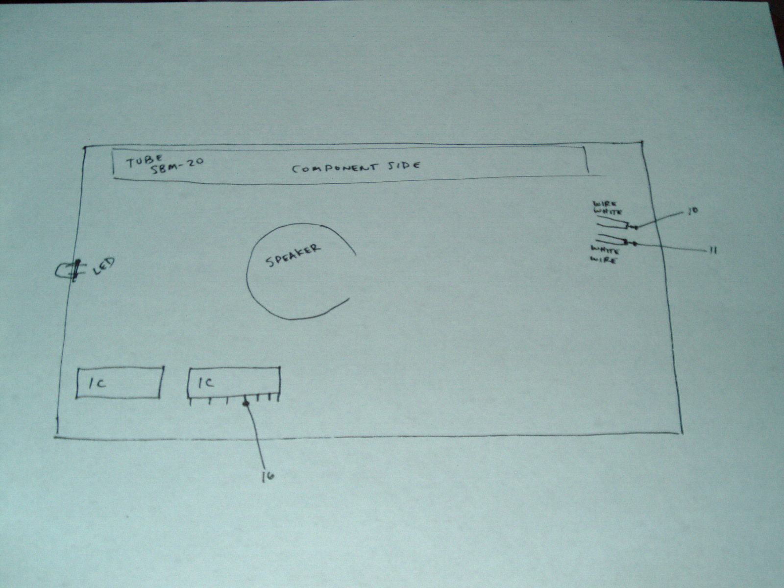
Update 1/3/15
Here are a few photos showing the cards just underneath the "metal desktop"
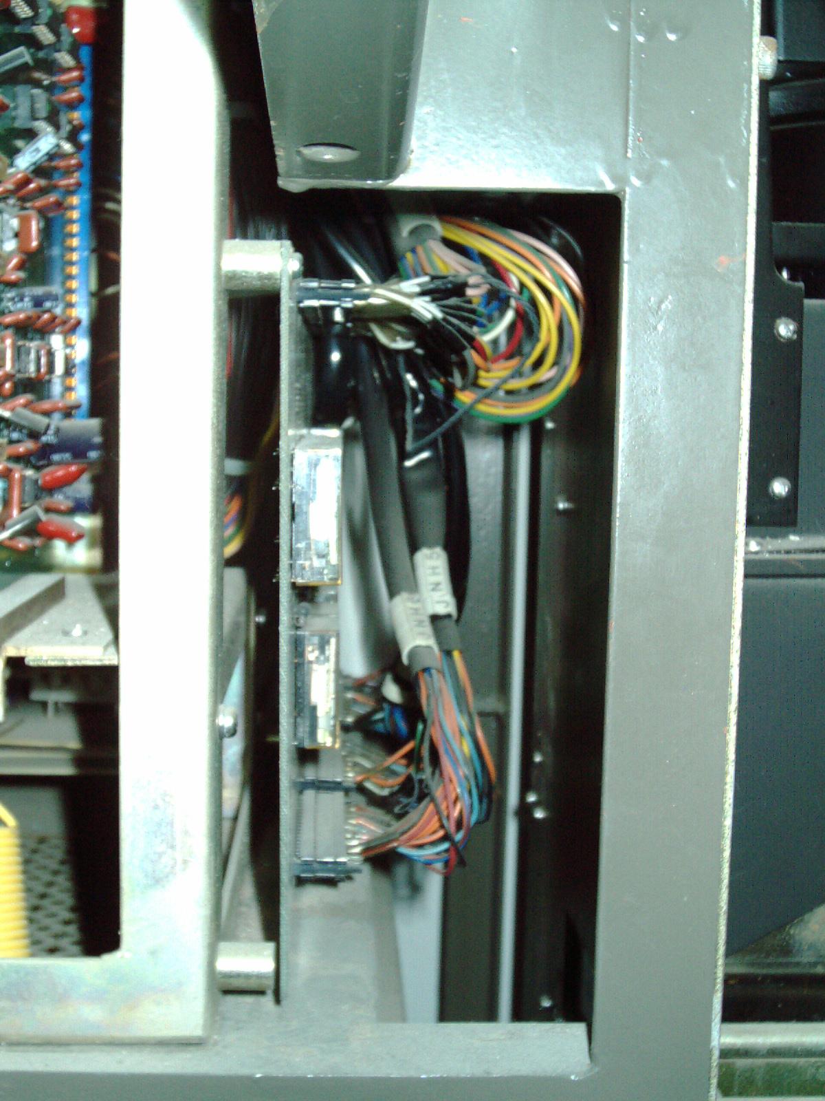
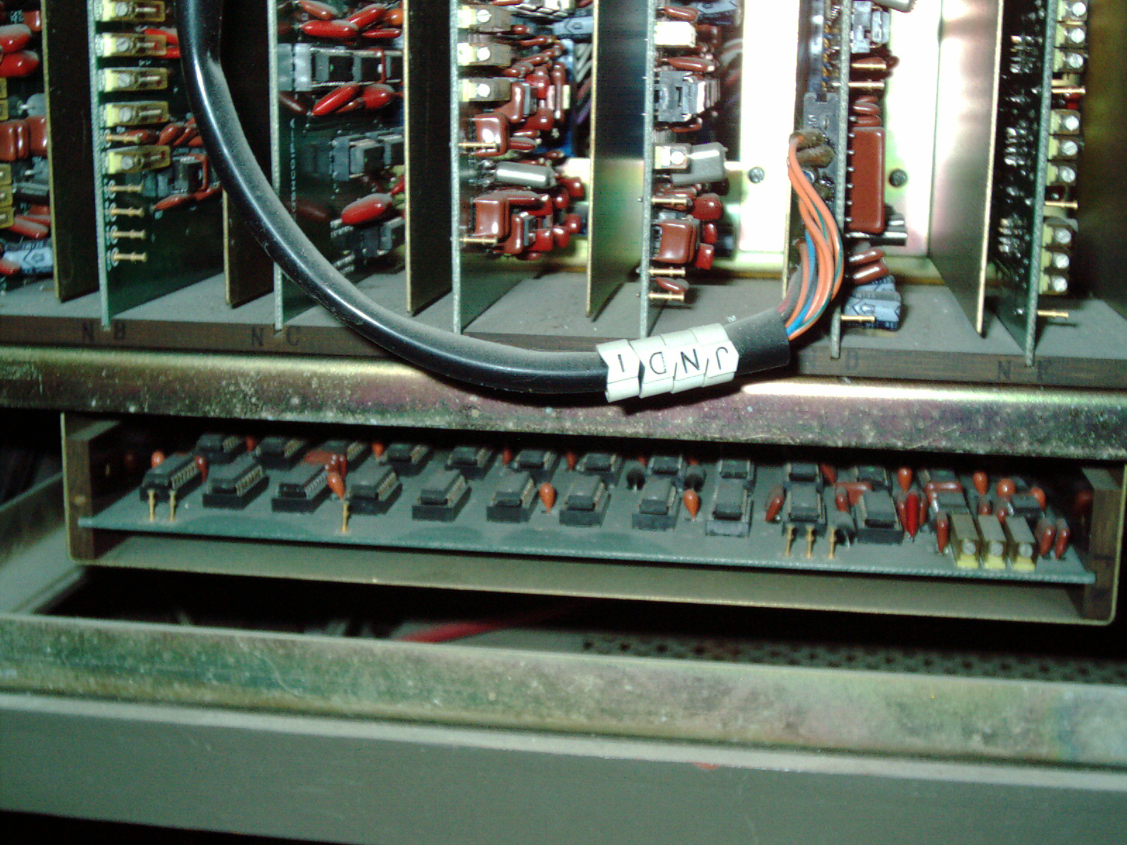
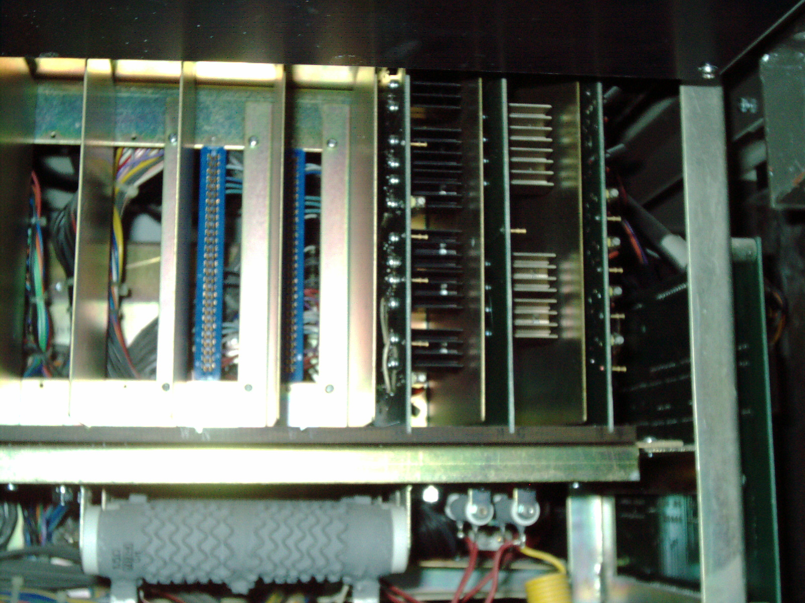
Here are a few photos showing the ports at the back/rear of the SEM (note that JN1 is for the Secondary Electron Photomultiplier and preamplifier assemblty. I have not attached it at this time - I removed it during transport in 2013 for safety but had to remove and replace the Hamamatsu R268 tube - see above for more infrmatio0n about this.
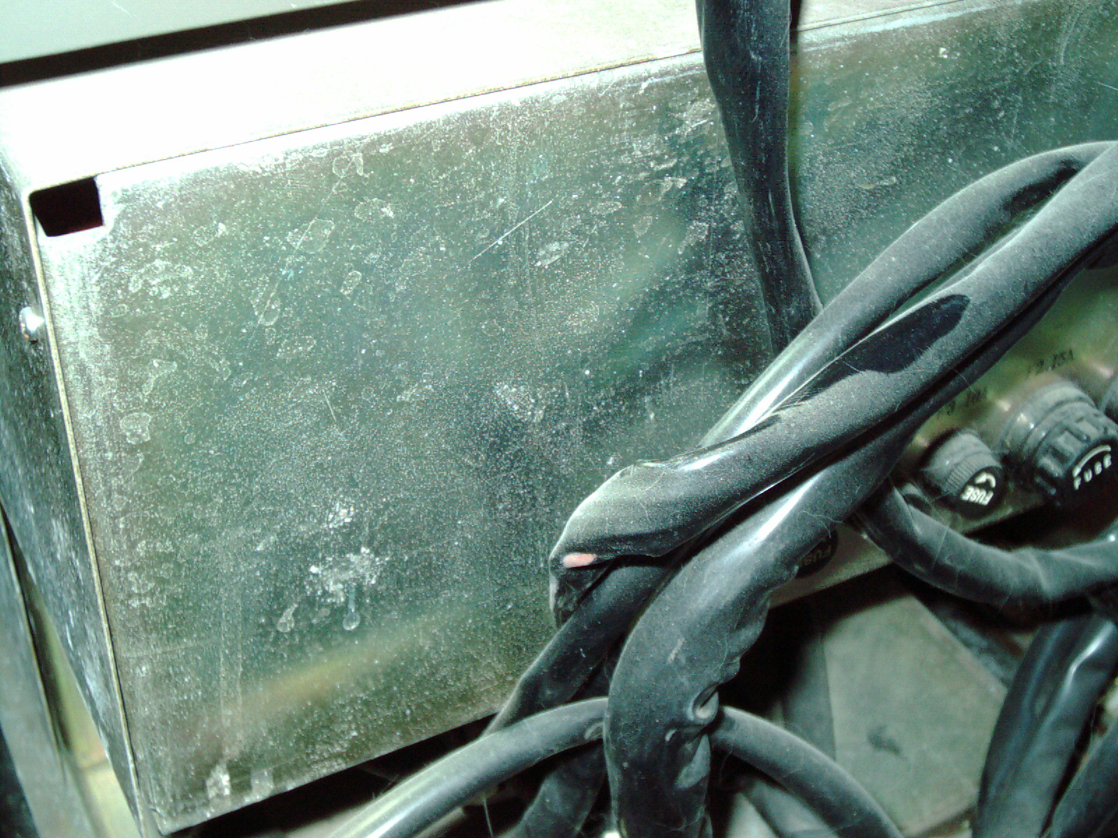
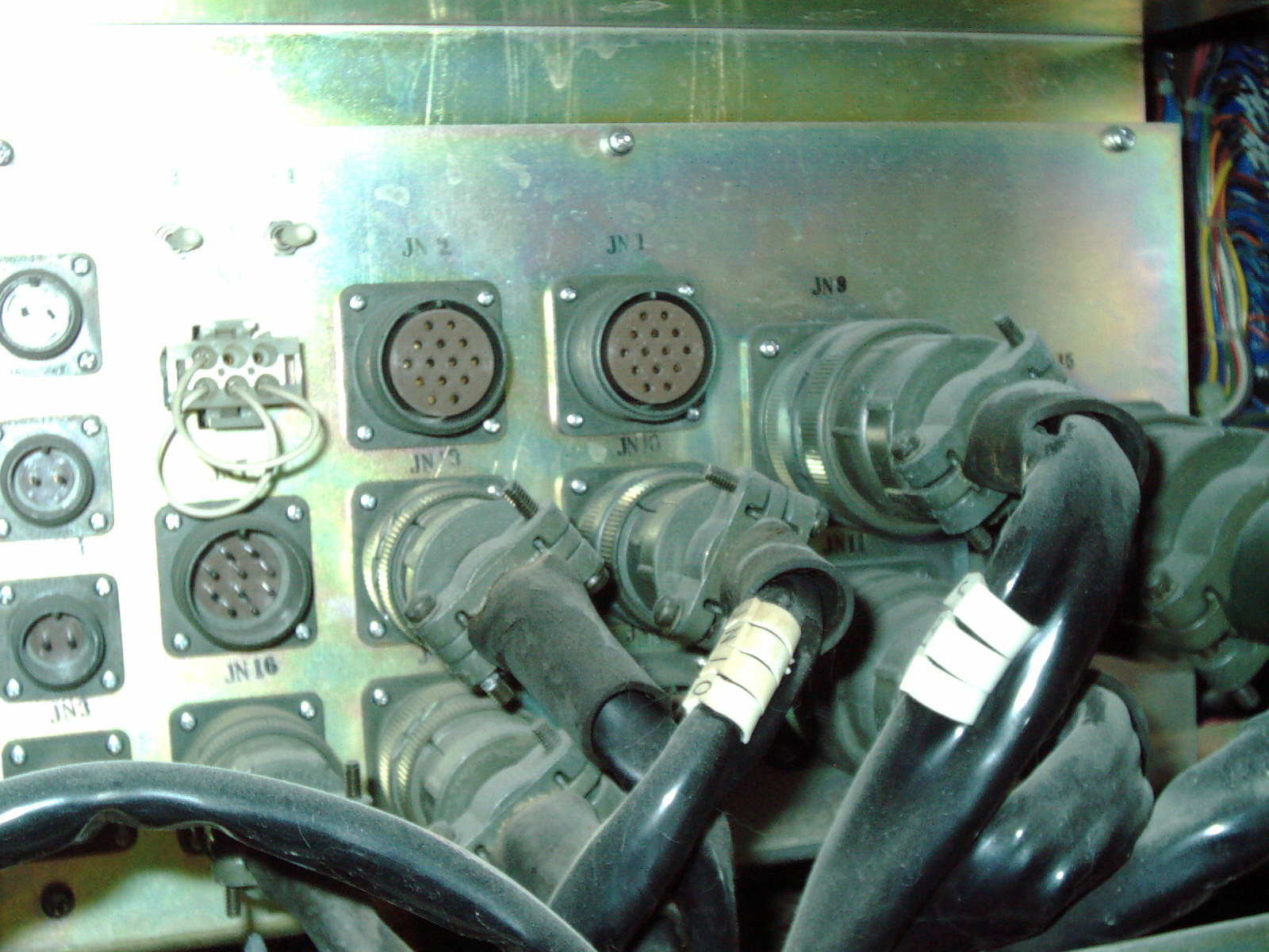
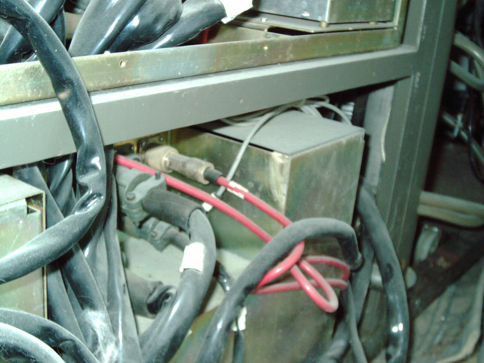
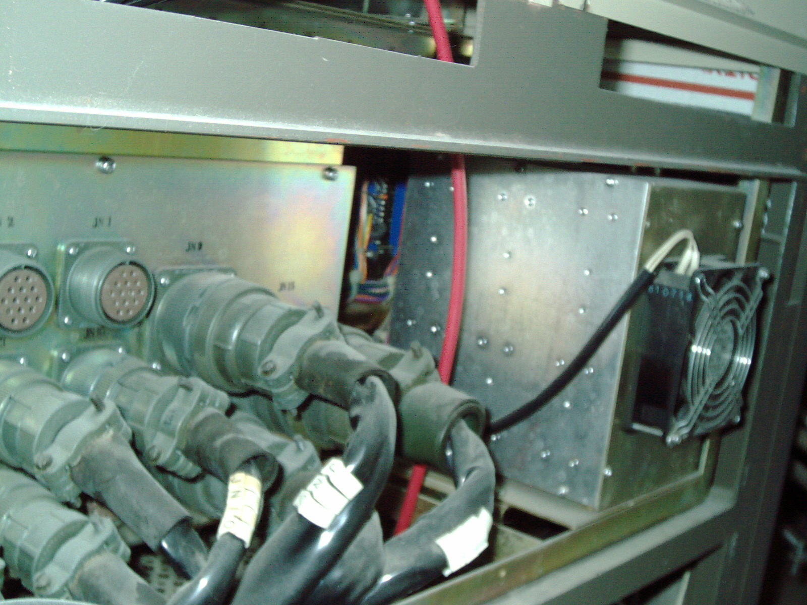
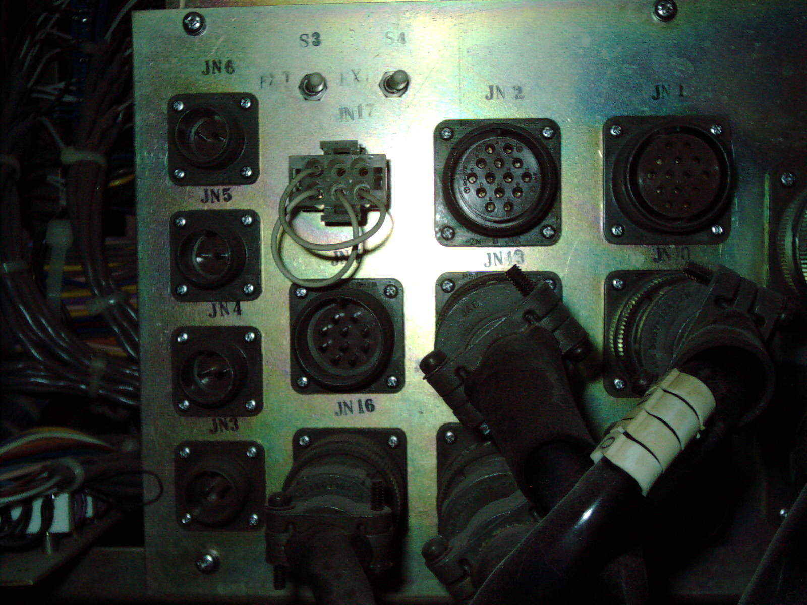
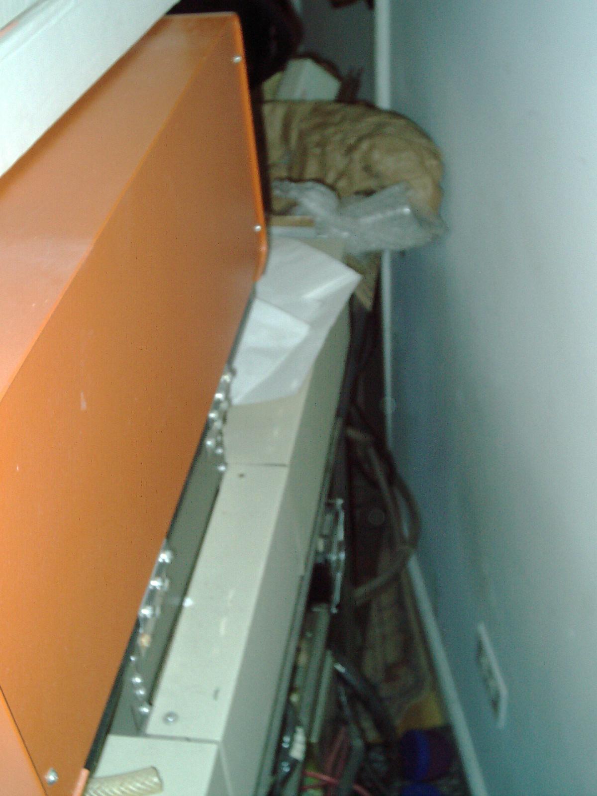
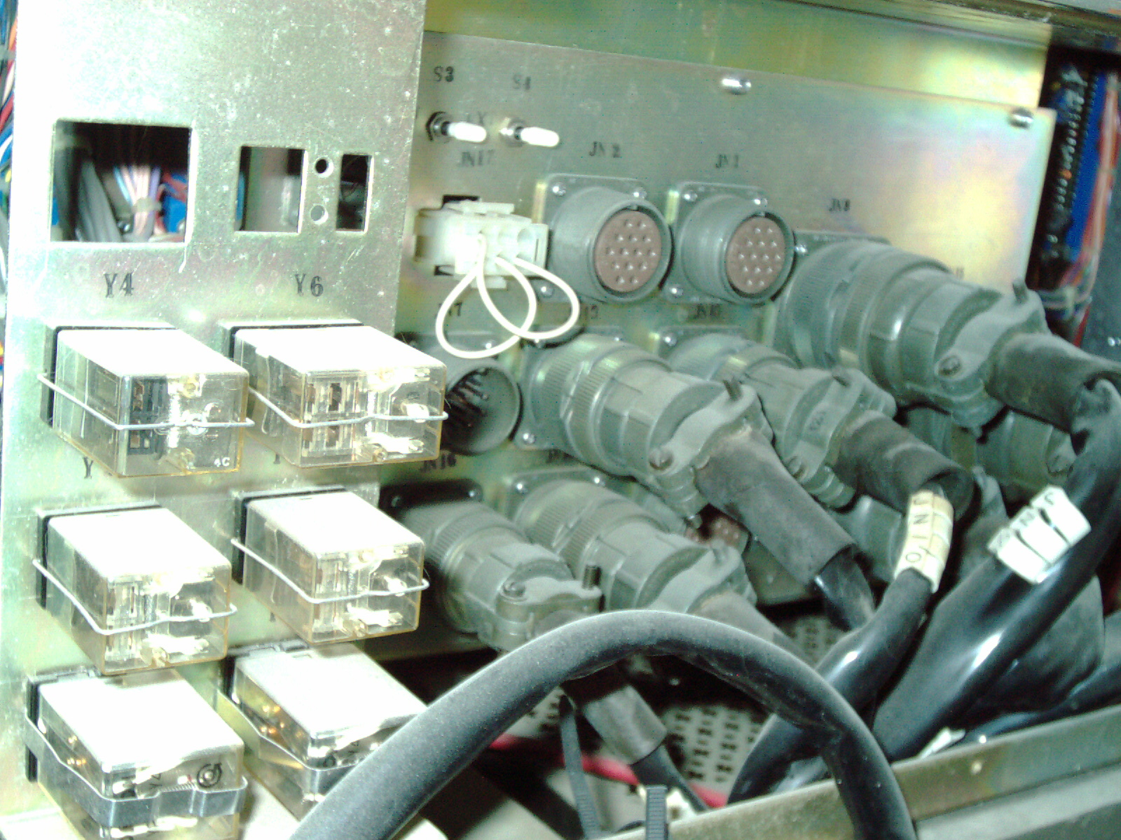
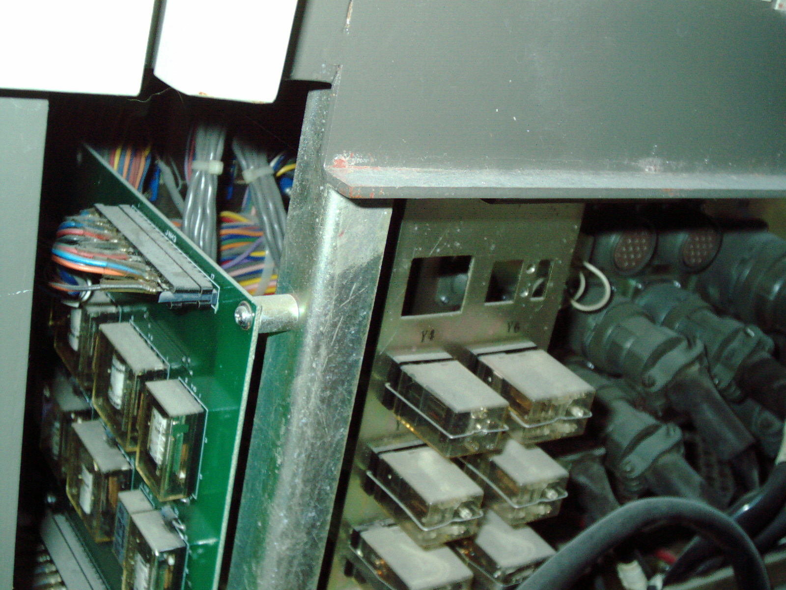
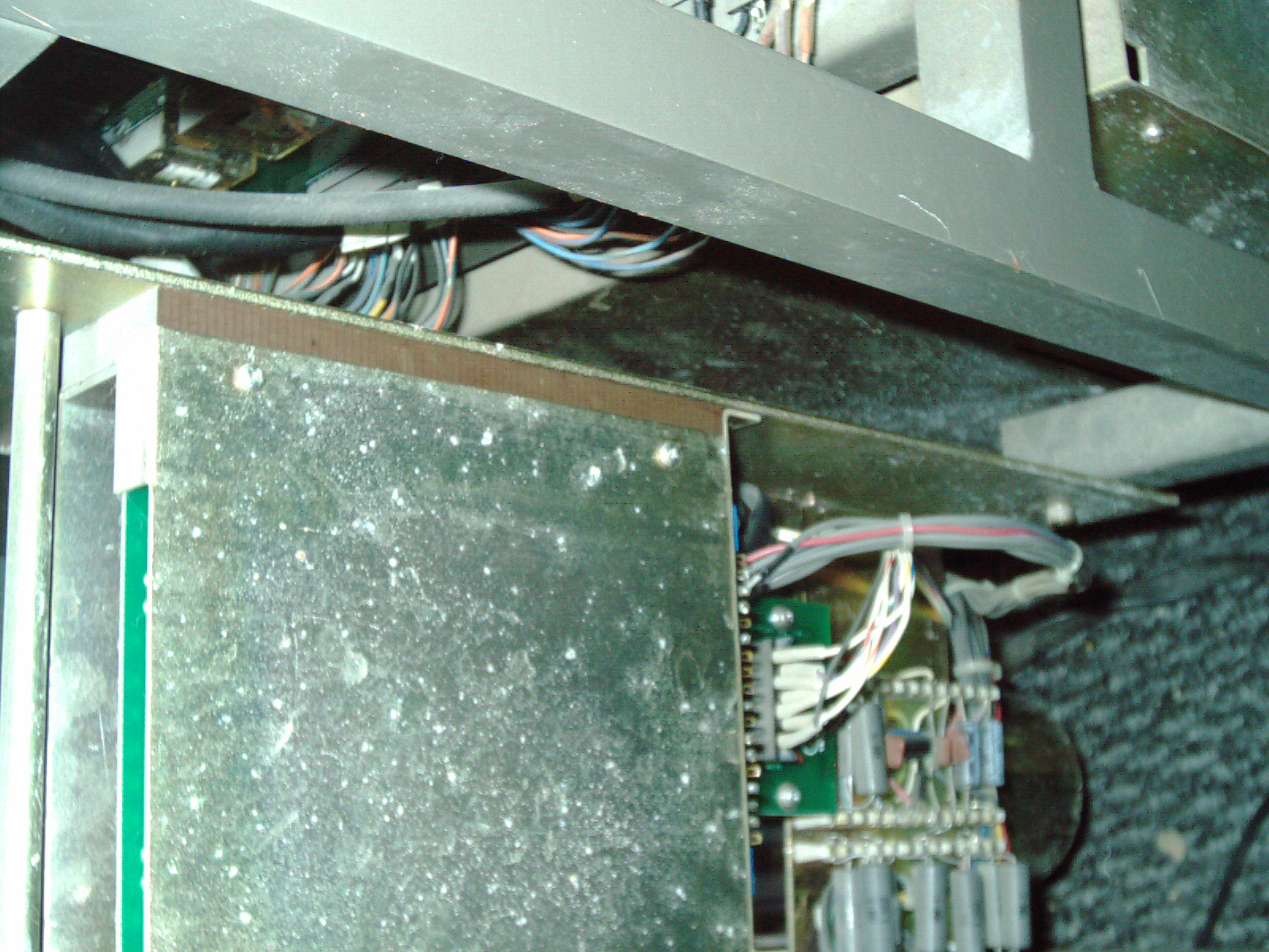
Update 1/8/14
I watched a youtube video in which scientists were speaking about the radiation in space and building shielding around satellites, space stations, spaceships destined for Mars in the future. These scientists were speaking of the concerns about this radiation shielding and about what happens when space radiation hits certain materials. For example - when a high energy particle from space hits a lead shield- the particle hits lead and breaks up into other particles sometimes more harmful than the original particle. These scientists said that sometimes using the wrong material can be more harmful than just letting the particle just go through- in the first place. This brings up some good points about lead and choice of materials. I need to research this some more. I need to find out what gamma rays and xrays turn into once they hit steel and rubber/neoprene and lead. It is possible once rays hit these materials - the particle becomes something else?
here is the youtube video which I saw (I'm not affiliated wih these videos - it is not mine)
https://www.youtube.com/watch?v=ADA-FtQ_Vno
https://www.youtube.com/watch?v=SB_7b5sJJco
Here are some videos about radiation and shielding (I'm not affiliated wih these videos - it is not mine) https://www.youtube.com/watch?v=AfSkUOwh41w
https://www.youtube.com/watch?v=aZNNfLDqMzA
https://www.youtube.com/watch?v=yrPocWyNJNY
https://www.youtube.com/watch?v=CtRroe_Qpuo
One of the above videos ahows a camping "mantle" onto which a solid aliminum IDE 3.5" hard drive was placed on top - the aluminum reduced the particle count but still - much got through. Another video above shows students measuring particle cound of aluminum shielding and even lead shielding and much radiation got through - lead being the best of the shielding materials in these experiments.
Aluminum as a radiation shield - some advantages over lead as in certain circumstances (depending on radiation source) as hitting lead creates other particles. ParticlesHitting aluminum as-far-as I have reasearched doesnt have the same negative effect - of creating unwanted other particles after hitting lead.
1/4" sheet of Copper is a shield for beta radiation but doesnt block gamma. I dont know if radiation which strikes it causes other emissions from the copper.
Here is a video about radiation shielding (I'm not affiliated wih these video - it is not mine) https://www.youtube.com/watch?v=z2duVJB0MiQ
Metals and water seem to absorb radiation. When exposed to radiation - metals and water themselves become radio active. This is my hunch as I observed these videos. My hunch may not be accurate but it seems radiation contamination radiates from metal and water objects. It may be that dust and contaminants within the water become radioactive? Those particles being radioactive within the water may explain why some scientists have found that gutter downspouts- the area directly underneath the discharge - that would explain why thise downspot areas are radioactive.
Here are some videos about radiation (I'm not affiliated wih these videos - it is not mine)
https://www.youtube.com/watch?v=CCrDcxz9gNk
https://www.youtube.com/watch?v=CcEyavzsyHA
https://www.youtube.com/watch?v=E5yZqxFh_3k
Air filters on cars and furnace air filters and even dust on cars is highly radiactive
(not my videos and I'm not affiliated with it)
https://www.youtube.com/watch?v=03zn5nFpp9w
https://www.youtube.com/watch?v=Y9qrGYCUb78
https://www.youtube.com/watch?v=fKTCS_CHXeY
https://www.youtube.com/watch?v=fKTCS_CHXeY
After viewing the above videos I realize that some of the people posting these videos have put themselves in harms way. I cant imagine the damage they have done to themselves by exposure to extreme radiation levels. Some people exposed themselves to high radiation levels for a short time (hours and some for days months or even years. Yikes.
I also see that dust is a big problem as dust is radioactive probably as residue from Chernobyl and Fukashima nuclear power plant explosions across the globe and dust eventually spread all over the world through weather and the sea and animals/plants/fish interactions in those environments.
My Observations
I'm going to extrapolate another safety issue that I havent read or seen. Based on furnace filters, car air filters and thin layers of dust wiped from dirty cars. I can extrapolate from that - that probably vacuum cleaner bags - which are just FULL of dust - it is very very probably that - it is probably the most dangerous source of radiation in normal daily life. Also changing these filters is probably very dangerous to breathe in - not so much due to the filth (but still for that reason too) - but due to the radioactive dust that is now everywhere on Earth. These vacuum cleaners concentrate that dust into several pounds worth of dust. I think the furnace filter and car wipes will pale in comparison to the lowly vacuum cleaner bag as far as radiactiveity. That is my hunch. I'll test that hunch when my geiger counter is repaired. I may decide to move my vacuum cleaner somewhere else for storage after I test it and see the readings on the geiger. I may also check the soil/pavement underneath my gutter spouts. Maybe that small area of soil under gutter spouts needs to be removed and discarded? Maybe extra care needs to be taken while changing air filters to avoid breathing in dust. Maybe fine filters on furnace heater is a good idea - mine just has a blue coarse mesh filter - which is no longer adequate for this millenium.
I spent some time studying the internals of the Anatech Hummer VI sputter coater and found some homemade jerry-rigging and bodge bodginess inside that I need to restore to how it is supposed to be. The factory didnt do that - the previous owners did that. I see electrical tape that is coming apart and a circuit breaker which is not connected to anything. Basically - it looks like the previous owner bypassed the circuit breaker and disconnected it - the two black wires that should be connected to the circuit breaker - are instead connected to a fuse (I checked this fuse and it is blown - doesnt pass continuity test) - the fuse was soldered onto to short wires and then stuffed into the connectors. This ridiculous bypass was then covered in electrical tape. I checked the circuit breaker and found it to be in working condition- so why they did that is a real head-scratcher??? I undid all of the lectrical tape and removed the fuse with bodge wires. I then reconnected the 2 plugs to the circuit breaker as it should be. SO that was UN-jerry-rigged and is put back properly.
I ordered a black female banana jack from big-auction site and is a very close match to the original cracked one. I made an offer for a replacement "threaded banana plug" on big auction site. I see several on there for $20 - $45 each which is an outrageous price for just one connector. I see some big electronics website selling a siomilar connector for $20 - $45 which is a strange price. I only see one online seller selling this for $3 each so if I dont get it on big-auction site then I will order it from there. Alot of sellers price gouging nowadays - especially on parts and scientific equipment (sheez).
I also thoroughly cleaned the metal aluminum box with Green Cleaner and toilet paper. There was alot of spilled oil and general grime and bits of styrofoam leftover from shipping etc.
The aluminum box reminds me of an APple IIe power supply and has a similar look to the metal (brushed aluminum with a yellowish color) I took the dinged panel off and took it to my workshop where I straightened the metal and the raised areas on the edges I planished on a tool that I made years agoi which I call "a planisher" which I use to straighten bent metal. It basically pounds the metal using a straight die. Then I filed the edges as straight as possible and chamfered the edges. It is much improved but still shows the scars of the vacuum pump banging around in there during shipping (when you ship your Hummer always remove the vacuum pump!!!)
I also studied the underneath area just below the vacuum chamber. I see various connectors. I also see a black tightening/loosening nut. WHen I loosen it - I can raise the stage where the sputtered samples go. Mine was all the way to the bottom. I raised it all the way to the top and then hand tightened the black plastic nut underneath - this secures the stage so it is locked in place. I'm glad I figured tha out because now when I order the borosilicate tube/cylinder I will get the longest size so I can fit taller samples if need be.
There is a broken wire which goes to the outside of the aluminum box which I need to put a new lug connector on. I marked the place where it should go.
I also tried to move the analog gauge back to the position it should be as it is crooked. I managed to carefully move it a little so it is no longer angled. But it is up about a 1/4" too high still but much improved.
I reassembled everything so things dont get misplaced. Then I cut a CD/DVD 100pk spindle to make a temporary cover for the vacuum chamber area. I see it is gathering dust and the plastic tube will help to keep it clean until I get a proper Borosilicate tube.
I also spent some time looking into oil for my vacuum pump and the various oils available. The mfg sells oil for $30 but has a $100 minimum order so I am looking into alternative oils. I think that oils with the number 19 in it are proabably ok or good choices that I see on big-auction site. They specifically say that it is compatible with "Ulvac" and several other name brand scientific pumps. "19 high vacuum pump oil" is what I searched for and is approx $30 with shipping for 1 quart. My pump is empty of oil as it spilled out during shipping. I dont dare plug it in without oil otherwise motor/pump damage definitelty will occur. My vacuum pump which came with my Anatech Hummer VI is a ULVAC G-50D and perthe specifications can pump down to 1.3 x 10^-1 and the MFG recommended oil is SMR-100 and has a oil capacity of 260mL.
Update 3/3/16
Using an online conversion tool I found that 260mL = 8.79165 US Fluid Ounces - which mean that one seller with a 4oz bottle would not be sufficient and even 2 bottles wouldnt be sufficient. So I will need to order a quart or more as I suppose mine is fully empty and also some flush out is recommended. A quart of oil has 32 US Fluid oz which means it probably is sufficient for a future oil change/flush too. That little pump is expensive even at big-auction-site prices- so being careful on oil change is a good idea.
Since the homemade fuse is blown and that circuit breaker/fuse bodginess job leads to the vacuum pump - it makes me wonder if the pump works or not. The bodginess fuse they used was a beefy robust BUSS ABC 15 which is a 15Amp and really should not have blown. I mean electrically - it should have been sufficient electrically. I mean it wasn't in good judgement to replace a circuit breaker with a fuse - but I mean electrically it shouldnt have blown. So that tells me I may have a bad motor or other component I have to troubleshoot later. On the other hand - it is possible the person who did this bodginess soldered in a blown fuse which they didnt test first?? I'm hoping for a nice easy repair.
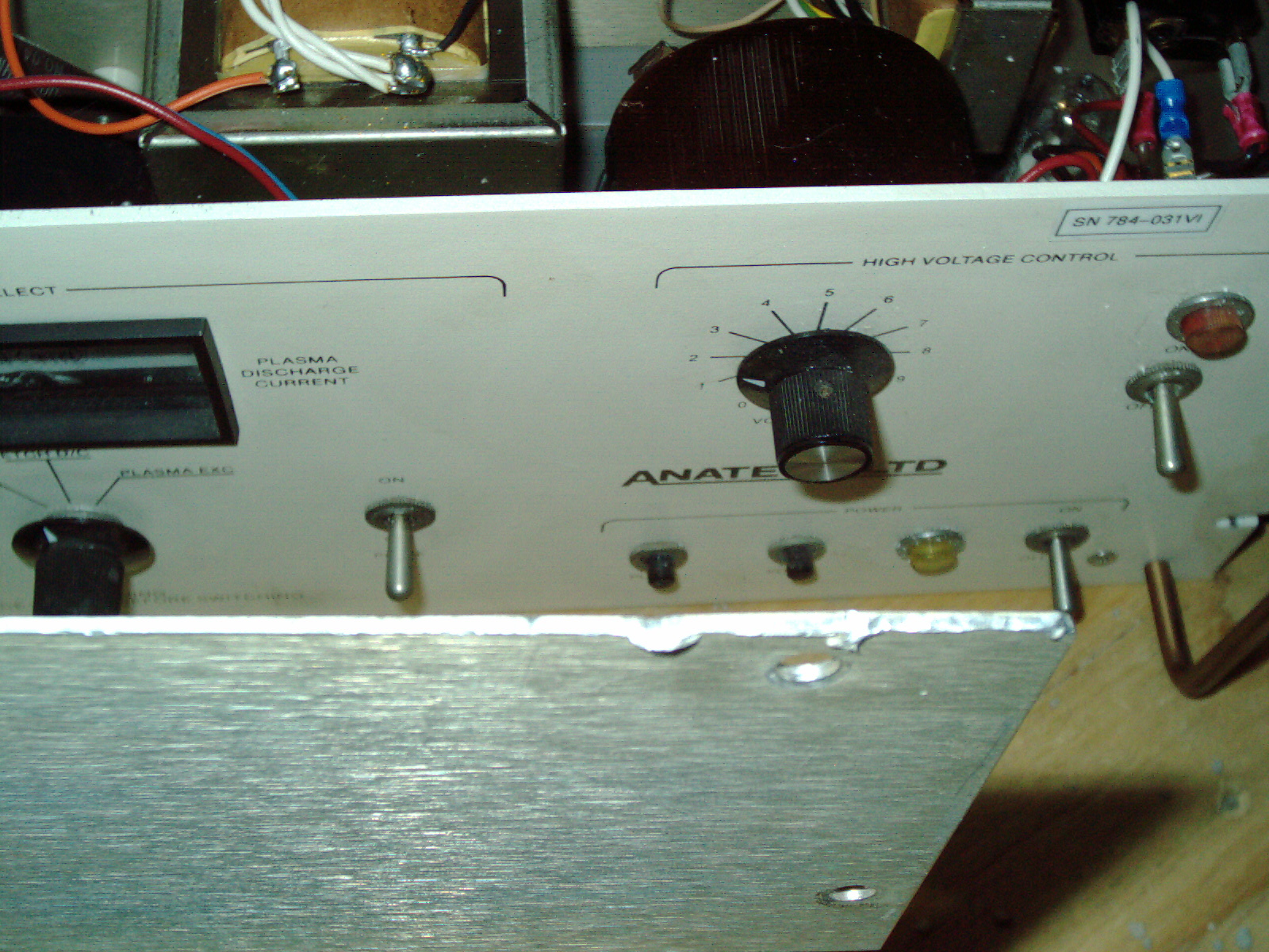
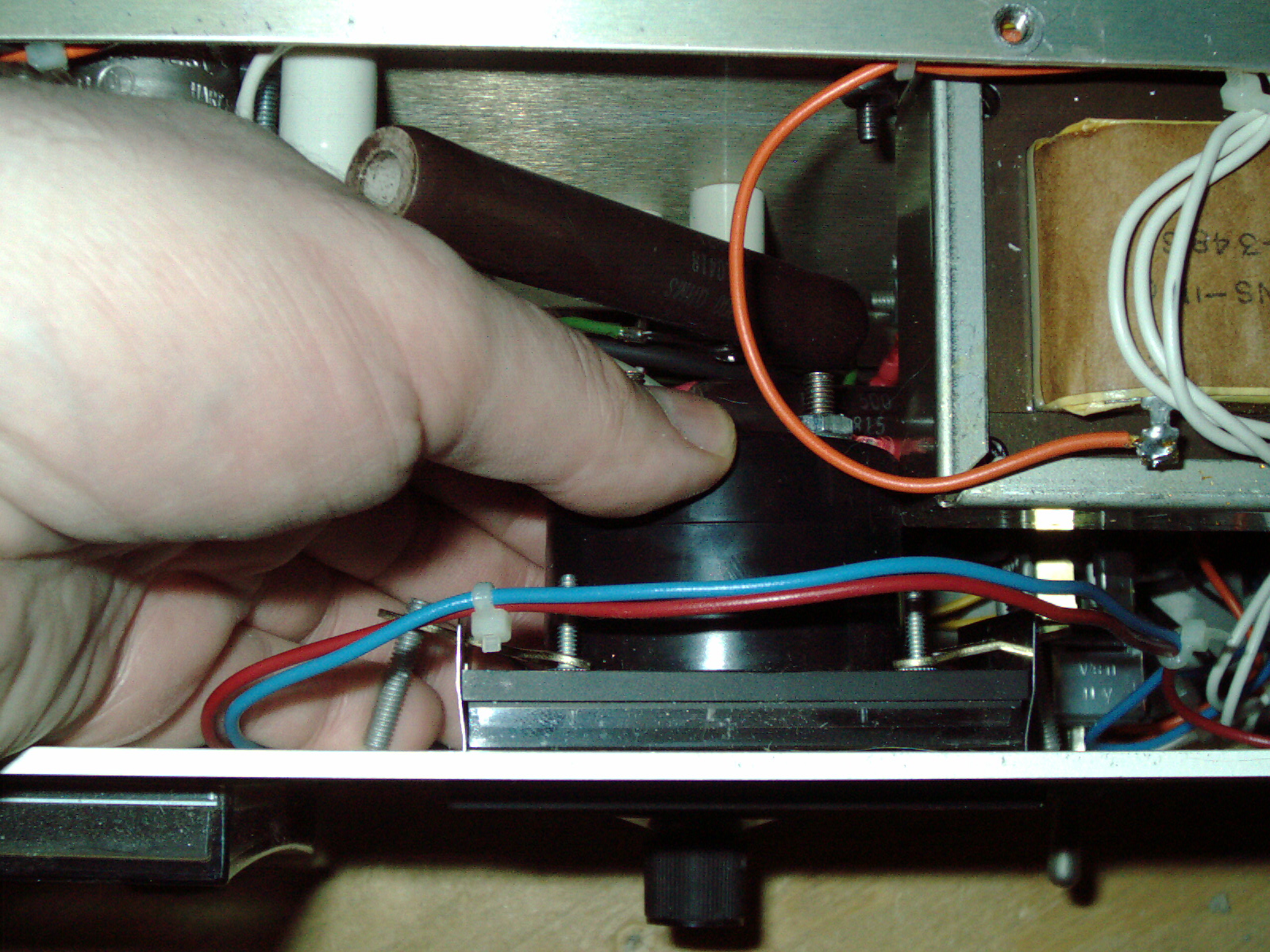
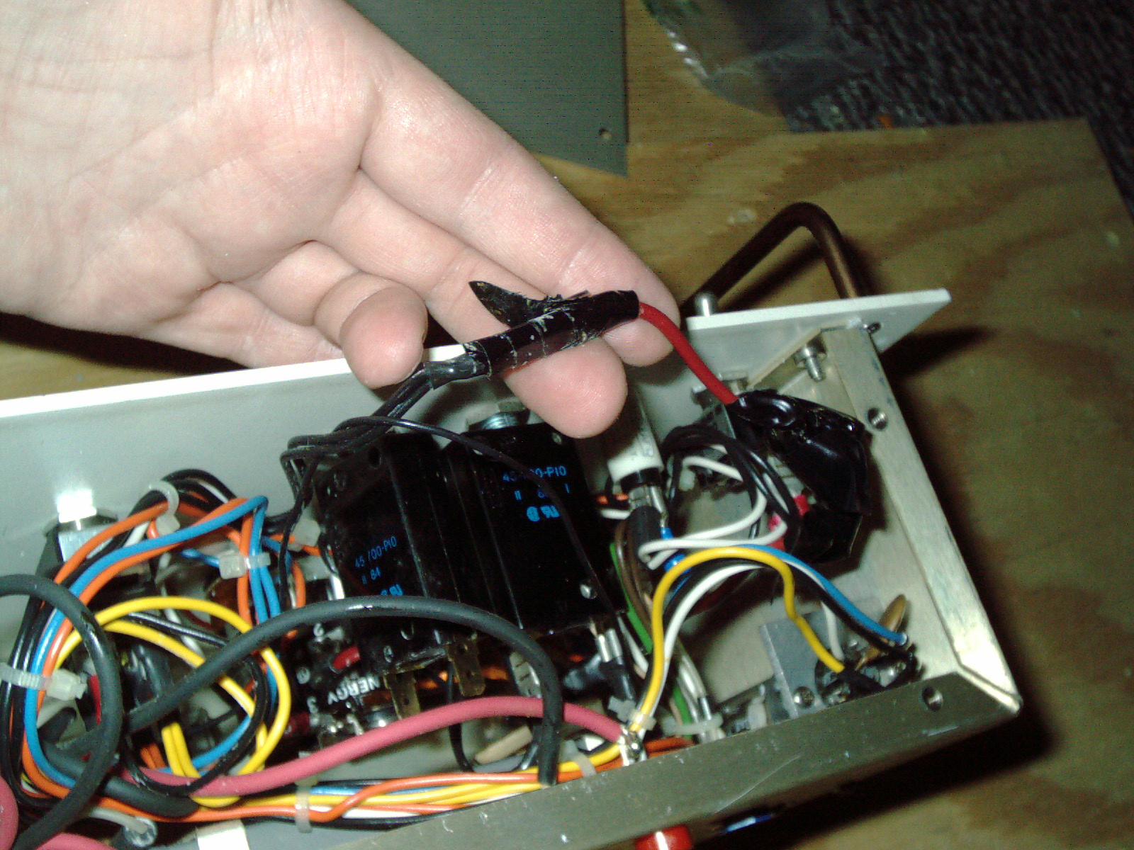
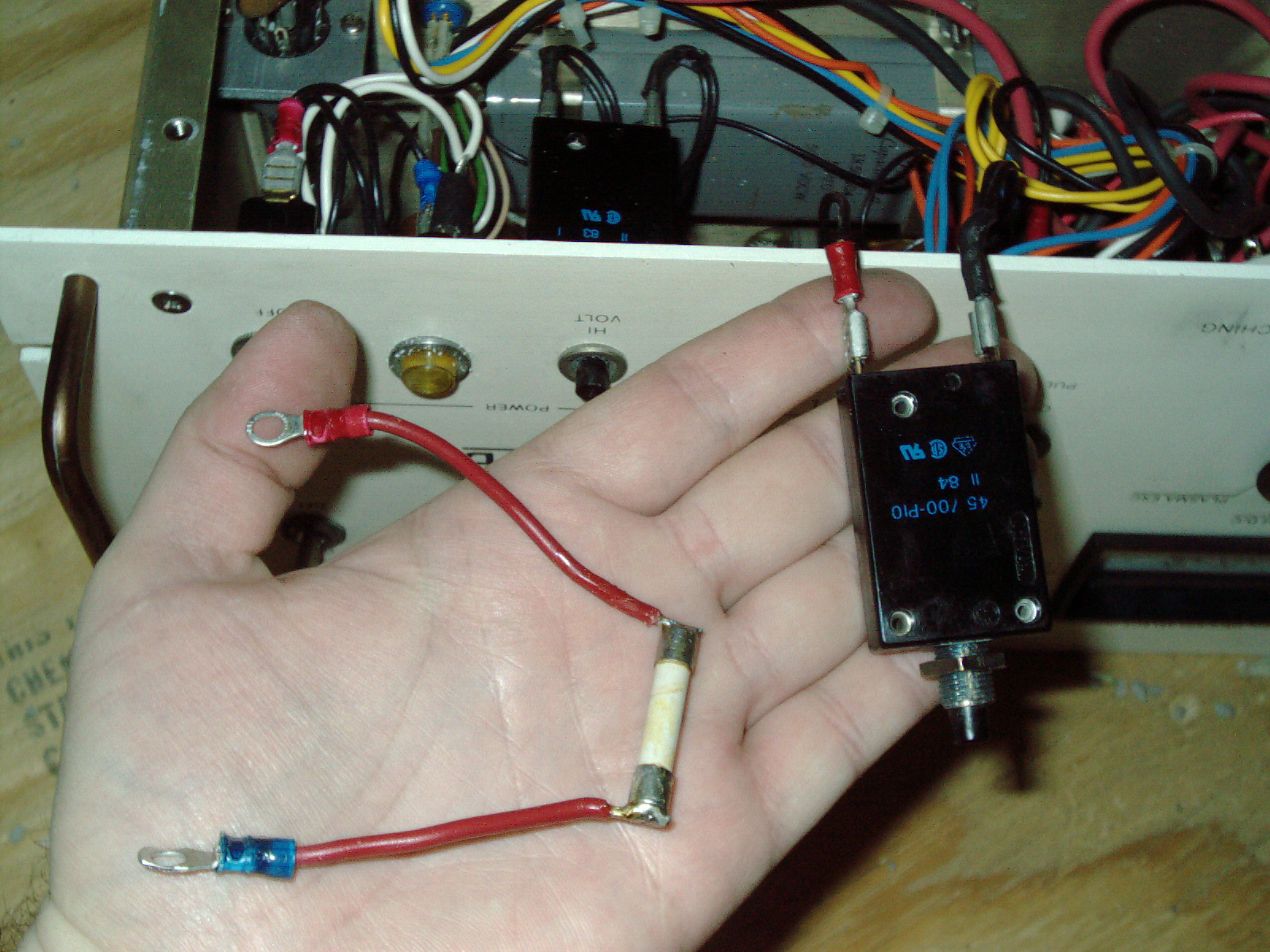
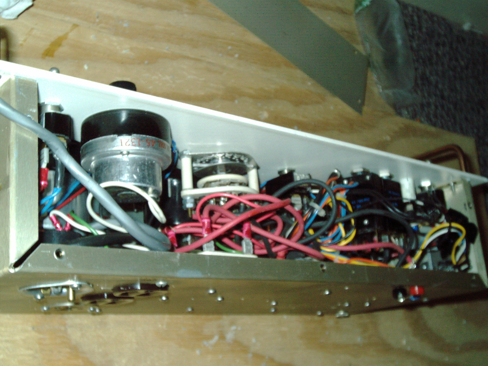
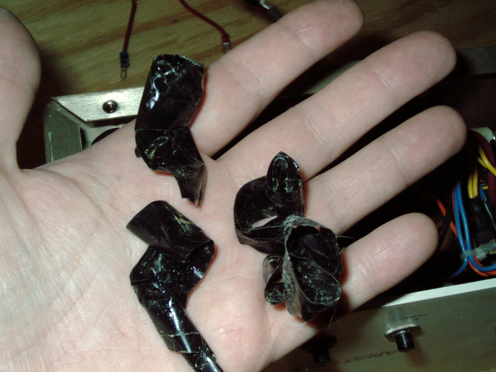
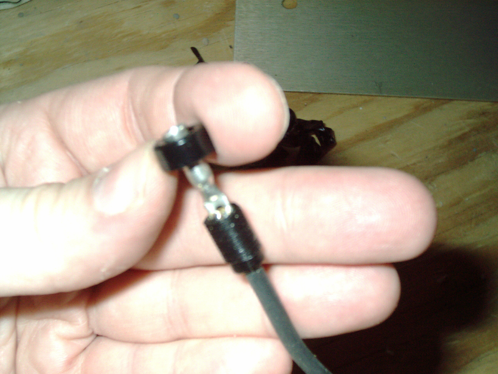
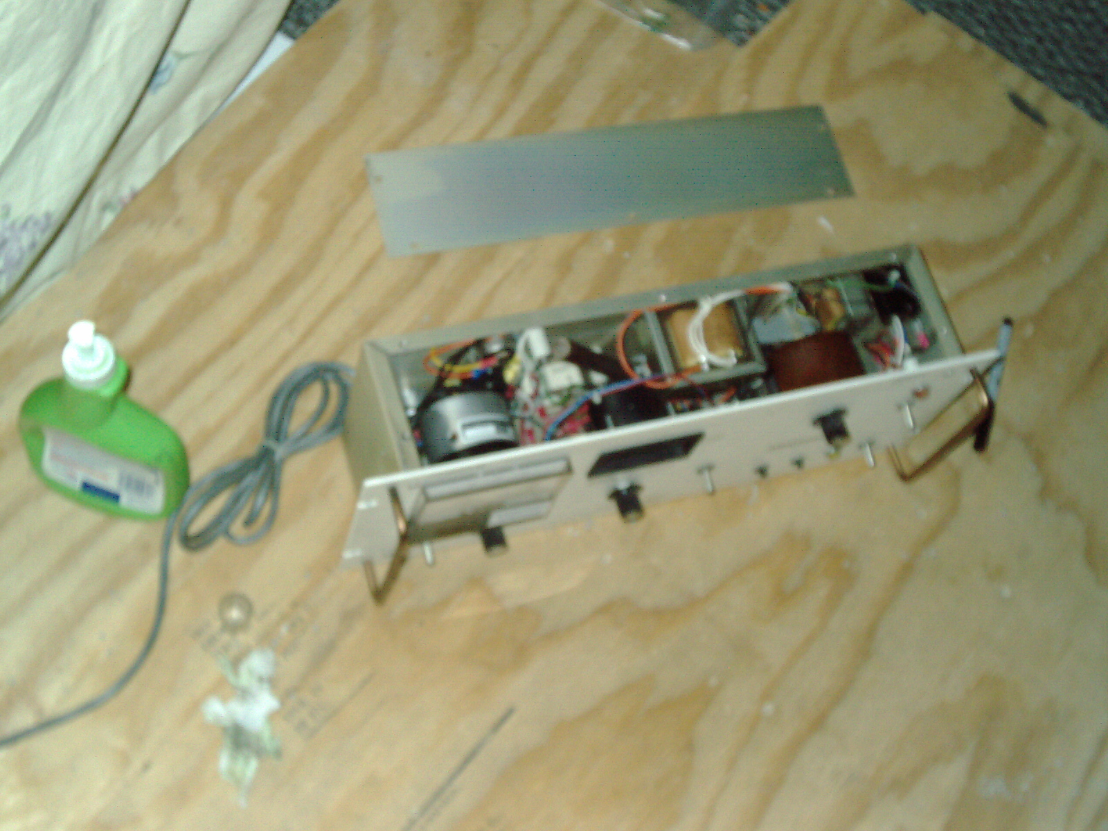
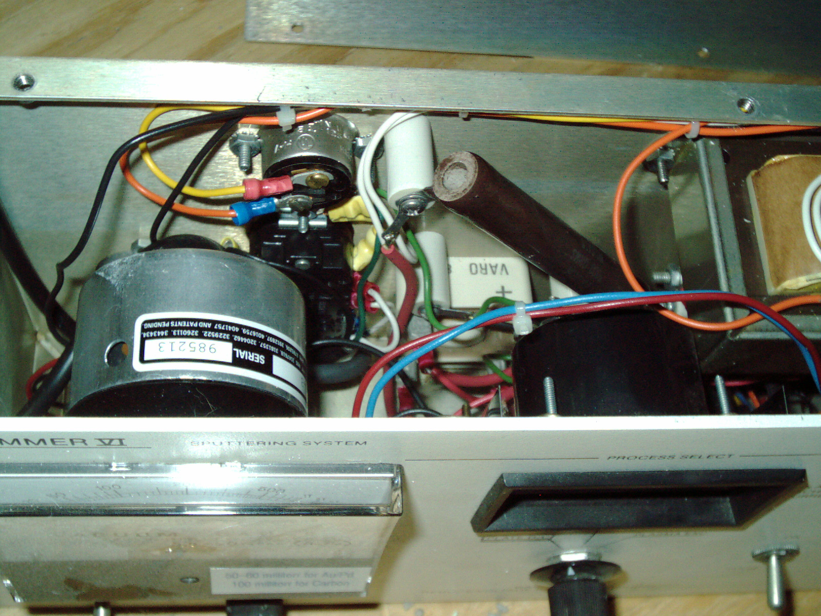
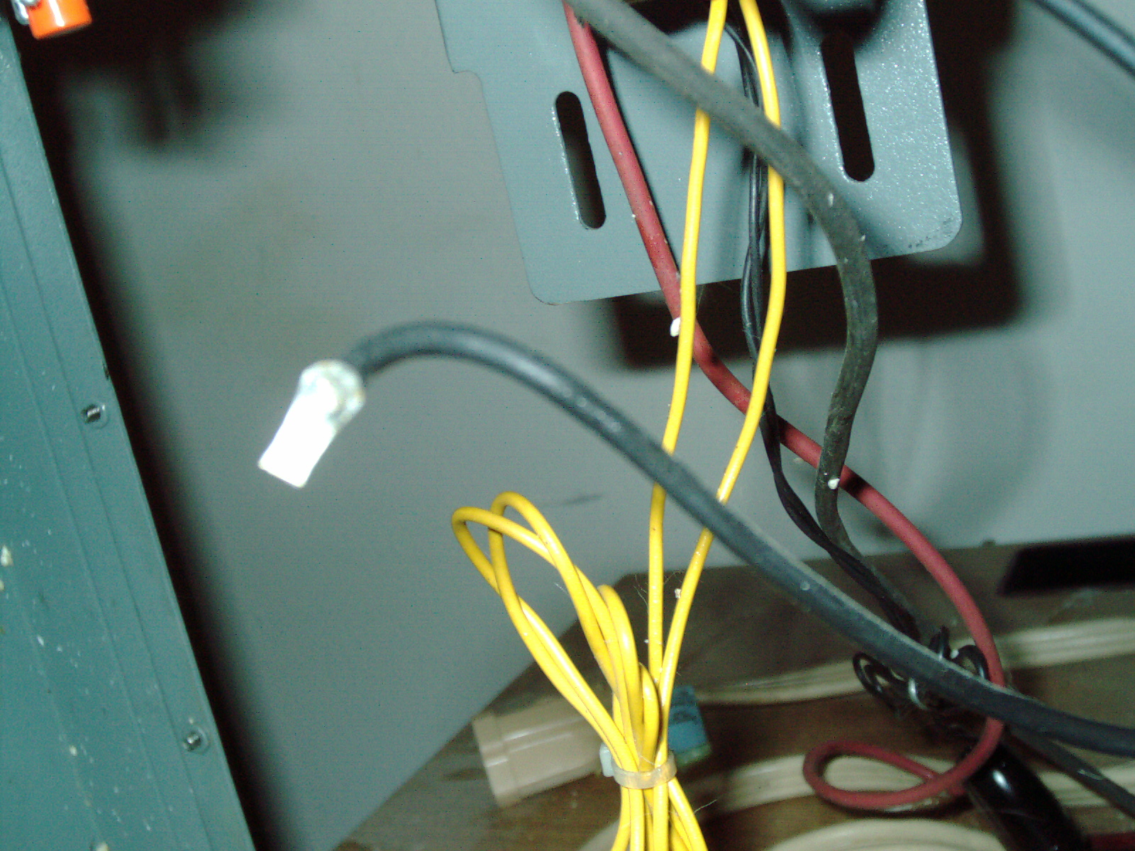
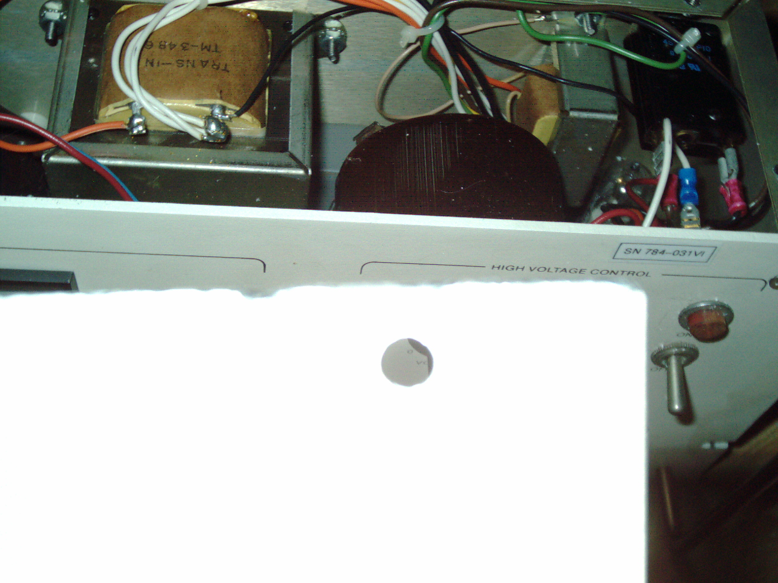
I spent quite a few hours over 2 days researching online prices and trying to find a replacement "banana plug" with a 8-32 thread. Big auction site sellers and other big electronic vendors had skyhigh prices ranging from $17 each to $22 to $40 to $55 for each one. Yikes. I made offers on big auction site but was turned down by 2 sellers. Bunch of price gouging going on. So I untimately found and ordered the right priced replacements.
A. 1ea red and 1ea black Female banana jack from big auction site $1.00 plus $1.75 shiupping for the pair
(EF Johnson Banana Jacks NOS. Part numbers are 108-0902-001 RED & 108-0903-001 BLACK w/nuts as shown.)
B. 2ea threaded Banana Plug Mouser.com part number 565-3264 $2.19 each plus $4.99 economy shipping
(Pomona 3264 Banana Plug w/Stud & Solder Lug, Thread 8-32 x 0.5")
C. My total for these parts is approx $9.50 whish is not cheap but is Very Drastically better priced than other places.
I made a great effort to find parts as close to original as possible with the same functionality. I'm not sure why the mfg decided to put screw-on banana jacks with 8-32 screw - but I didnt modify the design. I'm trying to repair it as closely to the original as possible.
Here are photos of these parts.
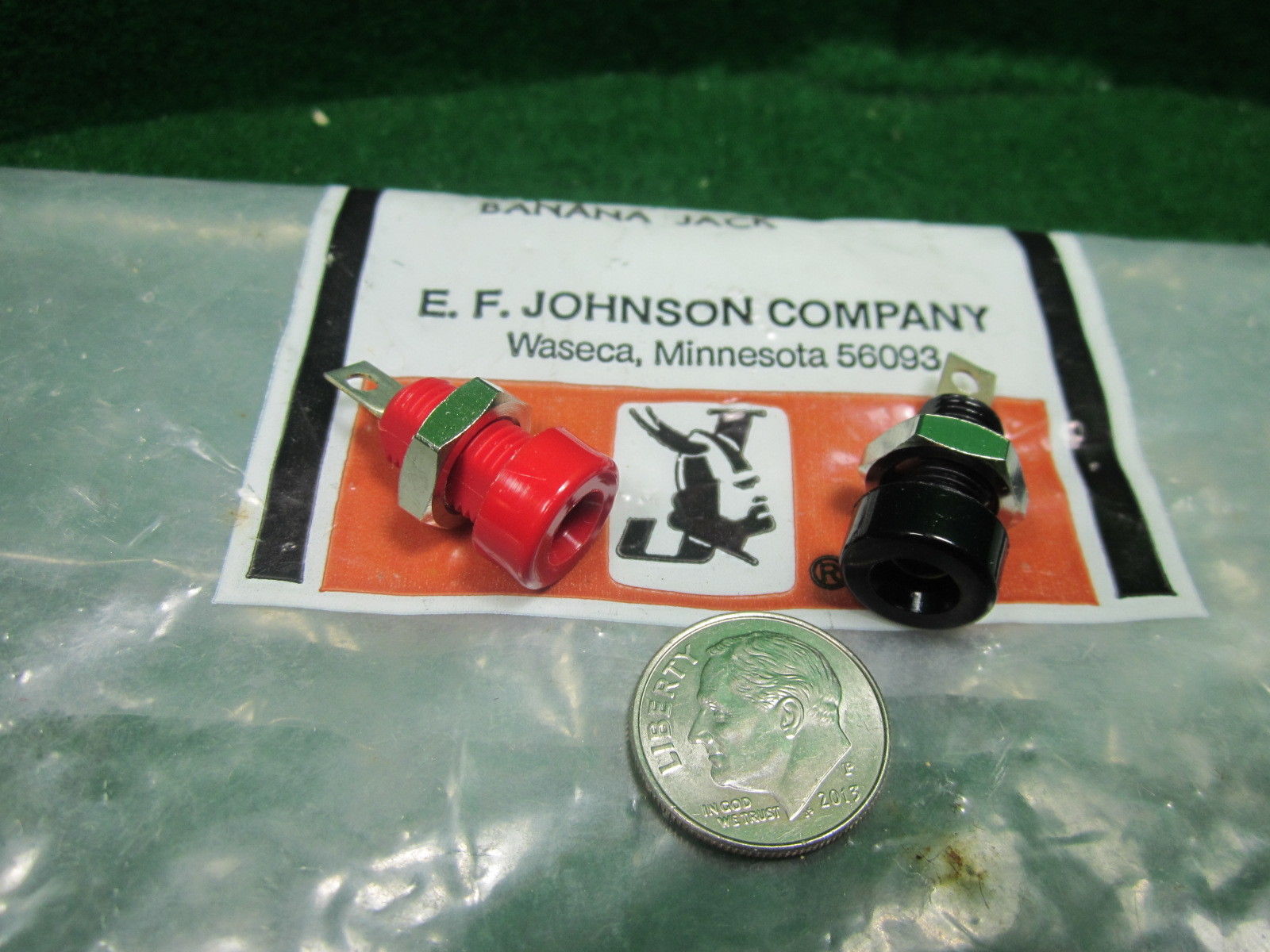
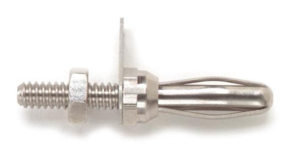
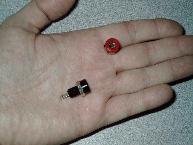
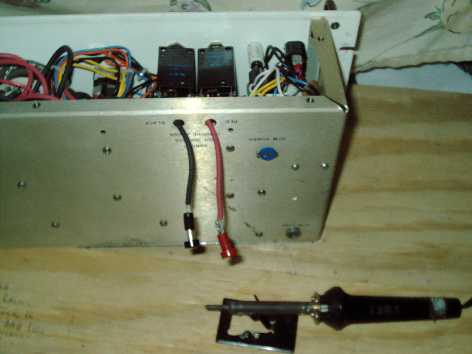
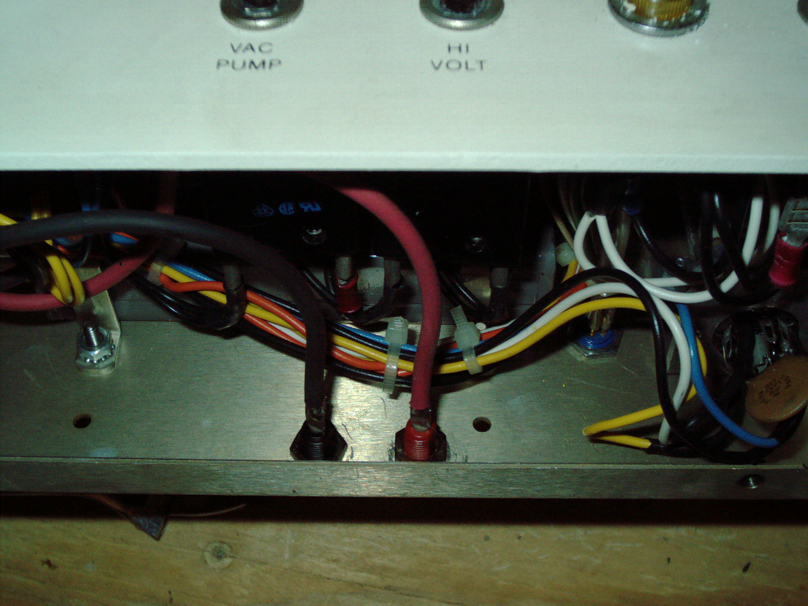
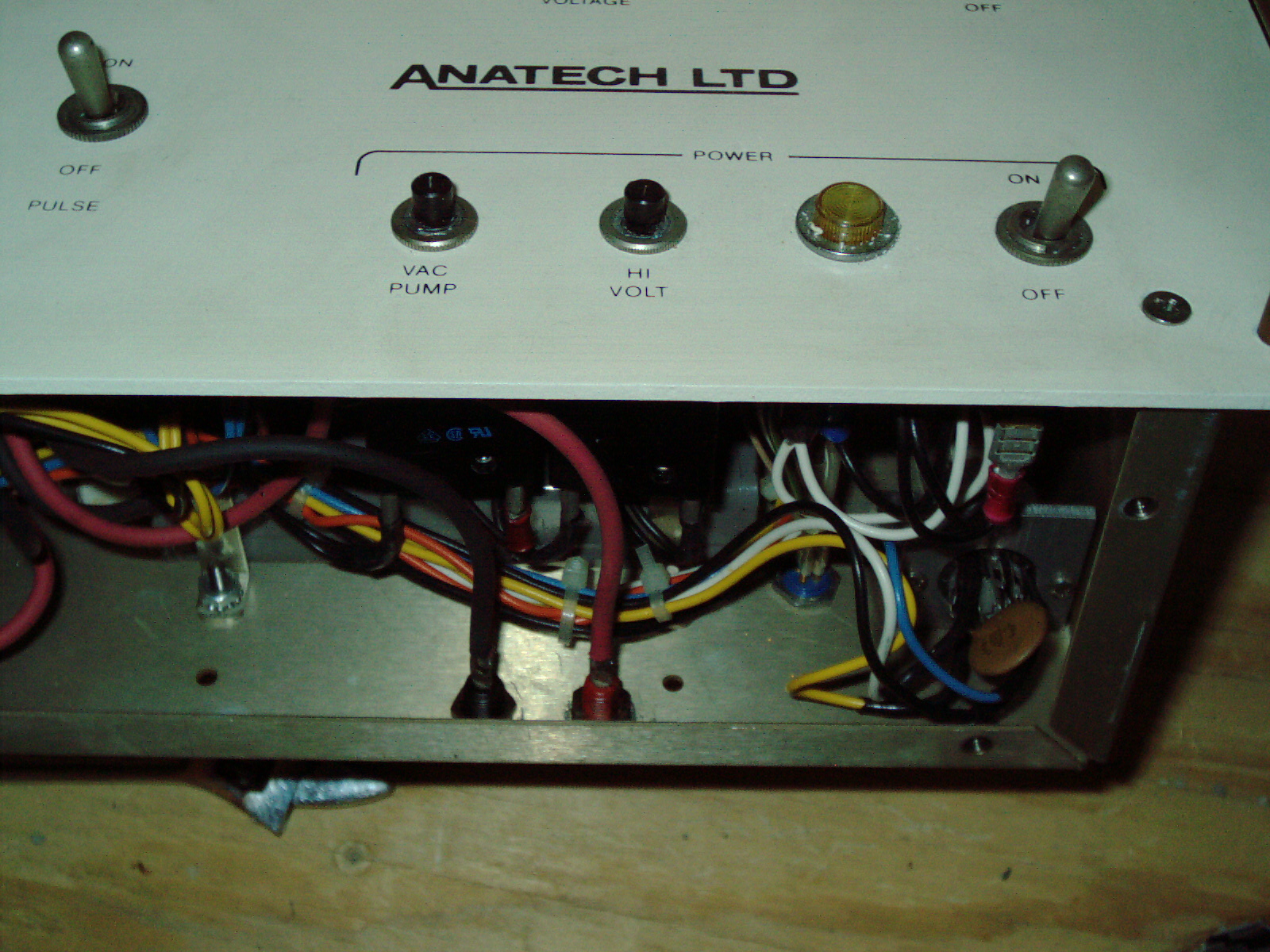
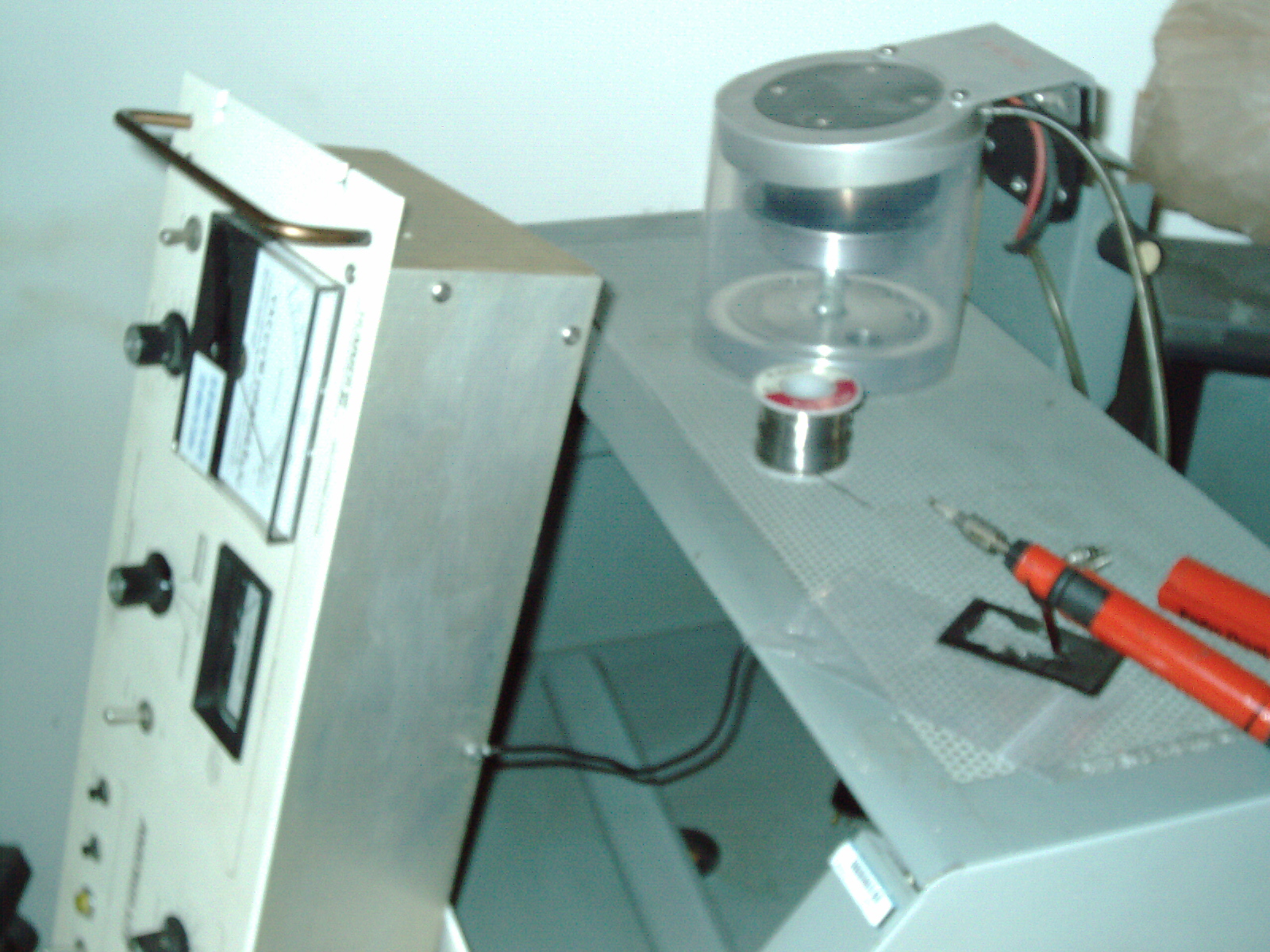
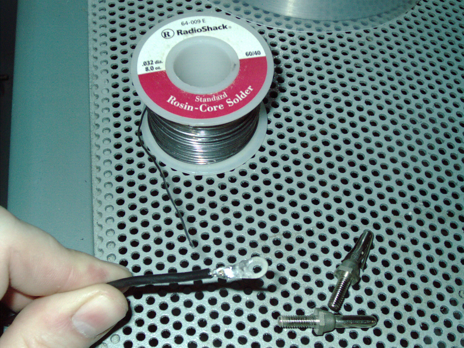
The 2ea banana jacks arrived and there was no retail packaging. Also notice that there is a flat spot on the side of the threaded portion. It just happens too often that sellers on big-auction-site play games and you get something where it is different than advertised. I knew there was a flat spot from the photo of their ad. But I'm wondering if the name brand is bogus also because it was not shipped in the package and only came in a vanilla tiny envelope inside a tiny box. I dont really know the name brand I received, But it will work for my application and I'm glad to have it. I will commence soldering and replacing the damaged banana plug and will change out both - just so they match; And, They will be the same. I am awaiting the threaded male banana plugs which should arrive any day now.
I researched the part on the damaged metal box were I believed a fuse should go- from the PDF file from a Hummer XP or X I read that the fuse and DTN jack are for a crystal which senses the thickness of the coating. I do not see any crystal or anything plugged into the DTN jack so this leads me to think that the fuseholder hole there is just a dummy. A fuse should go there if the thickness sensor is installed at a later date.
I borrowed my geiger counter to a relative where it will be passed around/shipped to various states to check around their households. One of whom has a radon remediation system in their basement. I hope I get the Bella geiger counter back someday. I would put a LOL here but I kind of feel bad loaning it out as I will need it someday to test this sputter coater and also my SEM. I got real lucky on that geiger counter purchase and also for an easy fix. It would be awful if it got lost of damaged.
Update 5/18/15
I got my Bella Geiger Counter back. Its nice to get something back that you loaned. I borrowed a Radon Detector and have been testing my household for about a week. Readings between .4 and 1.6 is considered very low. The radon detector is a digital model SP Pro3 (I may not have the name right) but my readings so far have been lo everywhere I checked. I also checked his household with my Bella and found low Beta and Gamma readings. So I was surprised to hear that he has Radon levels of higher than 4 and a mitigation system. That radon didnt show up on the Bella at all. Infact his household was very low in Beta and Gamma readings background levels were around 8 and some places 5 or 6. The highest reading there was a counterop at 14. Definitely very safe there for Beta and Gamma. I was pleased to see low readings at my house for Alpha Beta and Gamma. Im still testing alpha at my place but so far - nothing at all above normal background.
---------------
I just got done soldering the 2ea banana jacks and shortly afterwards the Post Office rang the doorbell and delivered the 2ea Banana threaded plugs. The banana plugs screw into the existing threaded mount just fine and are a decent replacement. Not exactly identical to the original bent plug but a good solid replacement. The original had a bigger "acorn nut" type head and the replacement has a smaller acorn nut. It is the closest match replacement as I could find. All of the more expensive plugs had the same style smaller acorn nut. The male threaded banana plugs came with 2ea solder lugs. I used one of them to replace the broken off ground lug which goes to the banged up/straightened aluminum case. I searched through my containers of misc screws which I have collected over the years and found a replacement short 8-32 screw with a similar philips pan head. This scrounged screw has a star washer built-in so I decided to use this scrounged screw to go where the lug attached to the case. The star washer will help to grip it and bit into the lug for a good connection.
I had everything all set to reassemble - but I decided to first open the aluminum case fully and have a look inside. The previous owner had jerry rigged a fuse to replace a "blown" circuit breaker which I tested as being good. Also the banan jacks someone was in there before as I saw the black and red one didnt match and the factory wouldnt gove expensive equipment a mismatched banana jack. So I thought - Id better look inside further to see if anything else doesnt look right. I looked over the transformers and wires to make sure no wires were crossed. I checked all of the insulation on the wires looking for points where a short could happen. I found the insulation good. Surprisingly I found a vacuum tube inside. Inside the vacuum tube is a coil of wire. I dont know what the purpose of that vacuum tube is. I decided not to fiddle with it as it is probably hard to find a replacement if it should crack.
Update 2/6/18 I am interrupting this paragraph 2-1/2 years after I wrote it- to say that I figured out what this vacuum tube is. It is a high powered relay which has a heater coil. When the coil is powered and hot- it temporarily bends a bi-metal strip of metal (like a thermostat spiral coil bends with heat) and makes 2 copper contacts connect. The heated coil requires a no-air environment probably because it is tungsten (like a filament lightbulb) and no-air environment also makes the copper contacts last longer - otherwise each contact would create charring from the air - in a vacuum - the contacts remains clean.
The ONE thing that I found was - the "fuseholder" for the DTM coating thickness - that really isnt a fuse holder as I thought. It is actually a circuit breaker which is broken. It looks the same as the other circuit breakers - except it is missing its reset button and I can see that the hole which is left from th emissing button - that hole is quite deep. SO I need to find a replacement circuit breaker which is a good match for the broken one.
The previous owner attempted a repair - which leads me to believe that the seller sent a damaged tinkered with sputter coater. Not all of the damage was caused by shipping. At least some of it was a pre-existing condition. I also see thetop of the case is dented down and some of it is dented up. I need to figure out how to remove the vacuum chamber aluminum base carefully - so I can straighten the top case without breaking the sensors attached to the bottom of the aluminum vacuum chamber base.
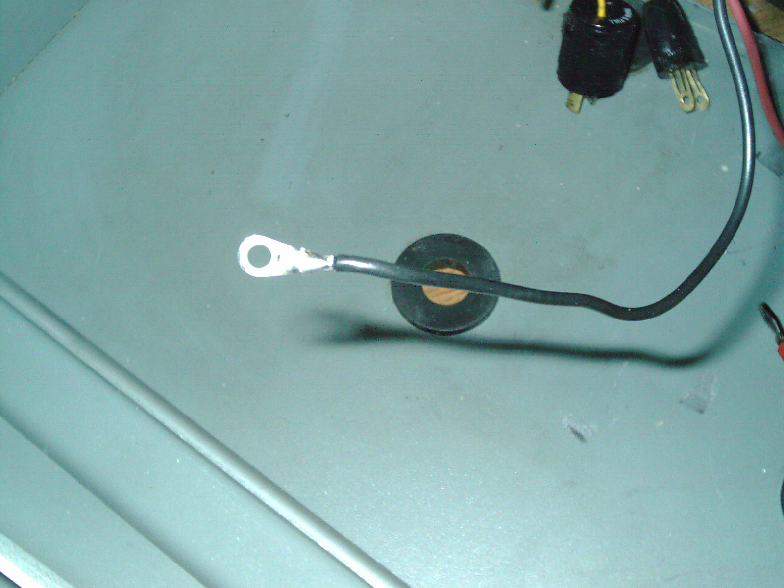
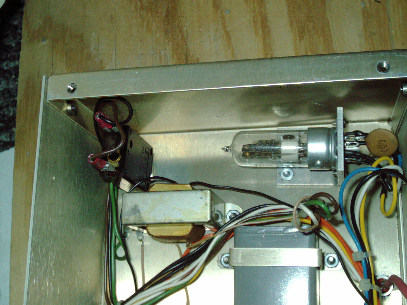
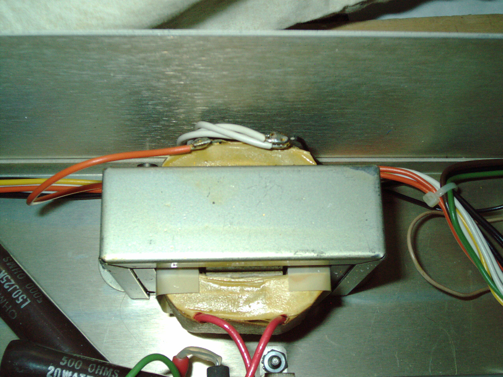
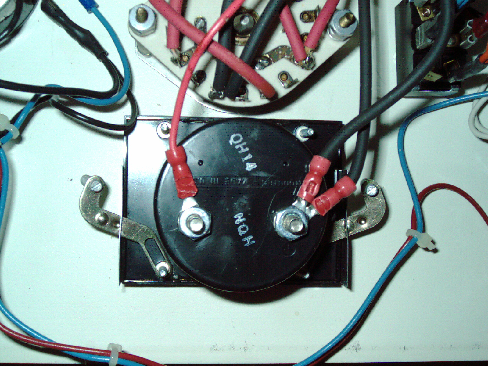
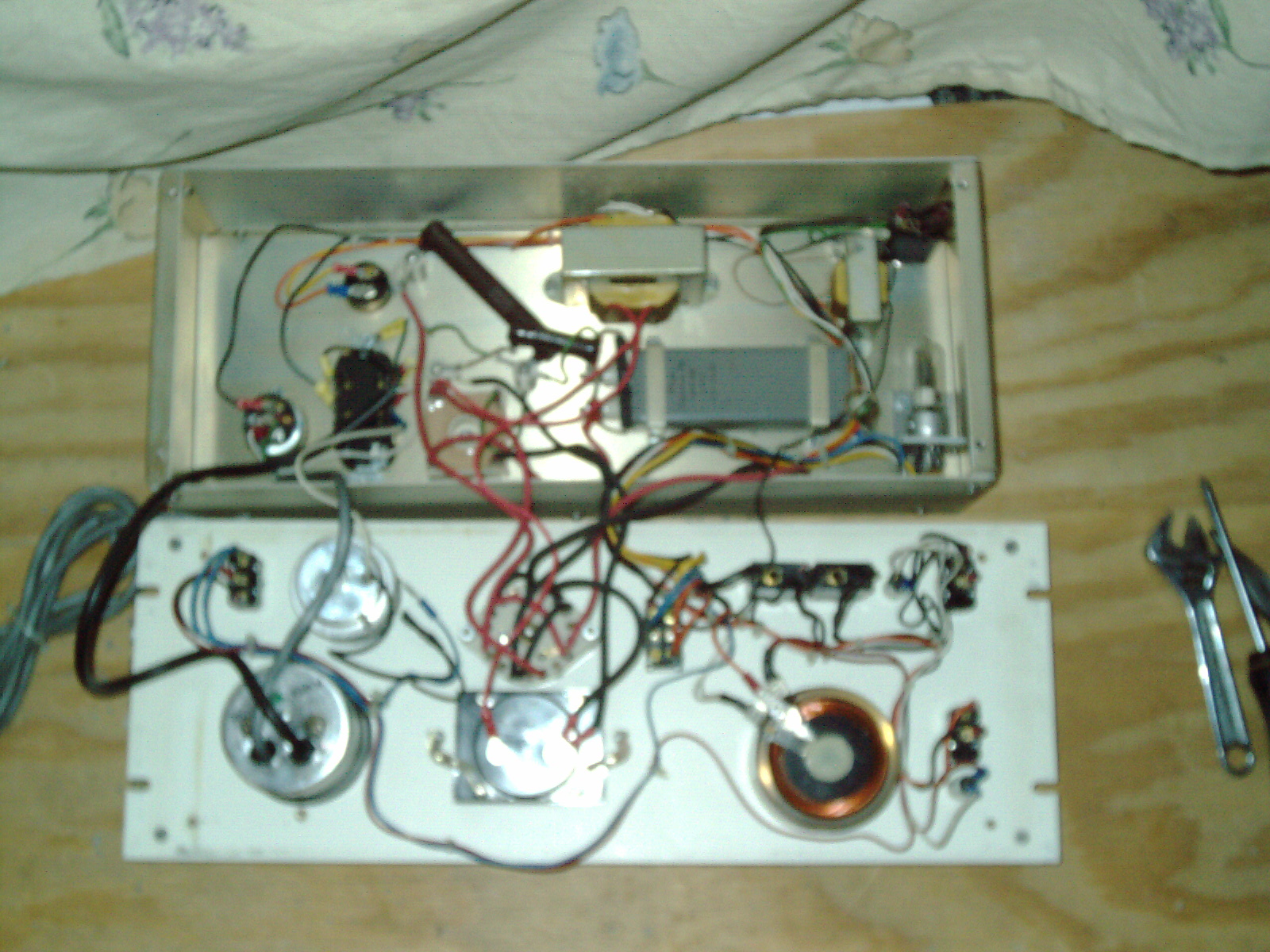
Here are a few photo showing closeups of the circuit breakers on the front panel (not my units - these pictures are from big-action-site)
|
|
Technics Hummer VI orange-ish brown with beige panels.JPG Size : 214.756 Kb Type : JPG |
|
|
Big auction site gray Anatech Hummer VI circuit breakers point 6 or point 9 and 1 on front panel.JPG Size : 290.265 Kb Type : JPG |
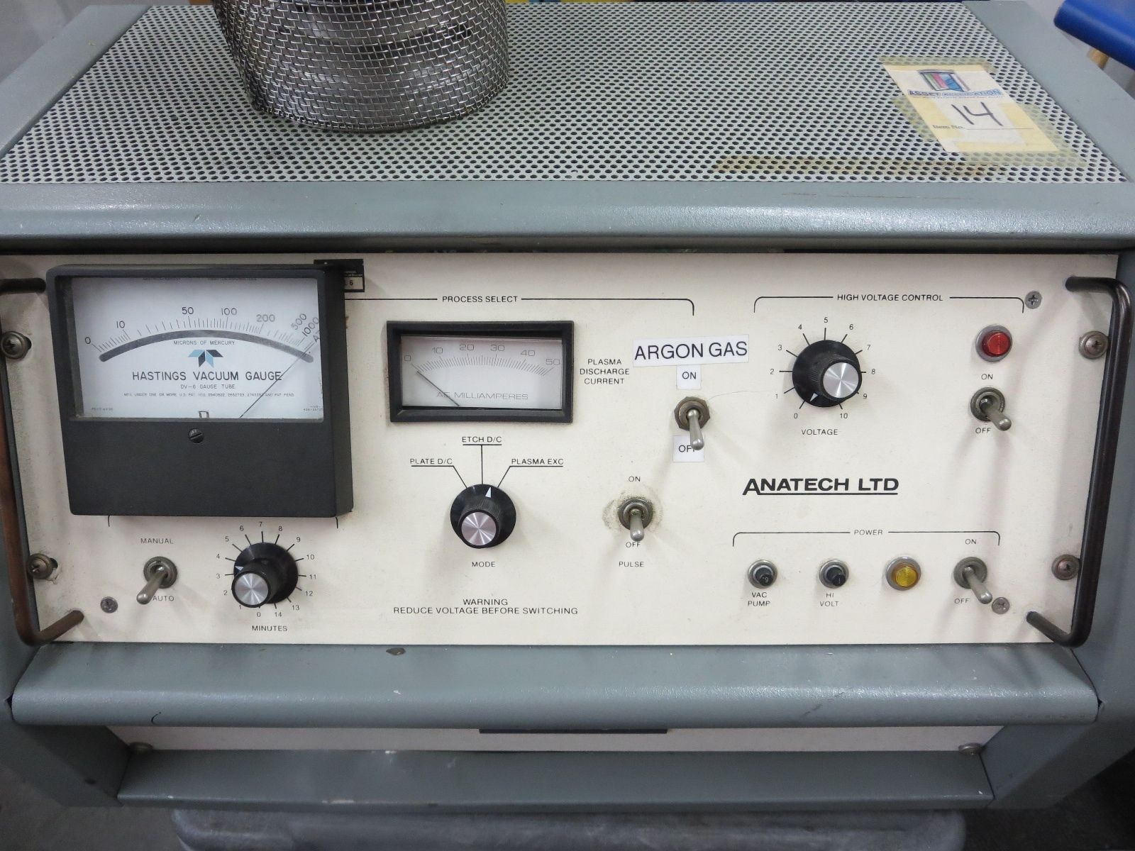
The following are pictures of some similar units from big-auction-site showing the internal circuit breaker - so far I have not found any picture which is clear enough to read this amp value. Unknown??????
|
|
Anatech Hummer Orange and black showing the rear and circuit breaker illegible.JPG Size : 385.03 Kb Type : JPG |
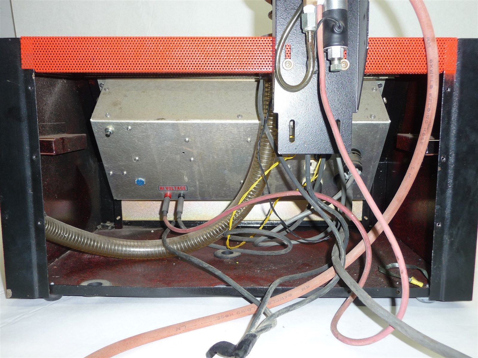
It is my opinion that the previous owner did not select the correct circuit breaker for the front panel. For example the circuit breaker for the vacuum pump is wrong. I see a 1 amp brand new looking circuit breaker but that makes no sense as the motor is rated at 4.3 amps draw- so this means that the circuit breaker would POP as soon as the vacuum pump started. Also right next to it is a faded looking 1 amp circut breaker. I think that faded circuit breaker is probably the original on the front panel. As I look at other units similar to my own - from photos on big auction site - the front panel circuit breakers are very worn - like the users were pressing these buttons often - often enough to wear away the printed amp rating number from the top of the button. I think the backside circuit breaker would not get pressed very often and proaby would have no wear on the printed number. I only see one kinda sorta clear but not extremely clear photo of a similar unit showing the back circuit breaker and it kinda sorta looks like a "1" 1 amp.
So it looks like this happened to the previous owner -
1. The left circuit breaker broke (on the front panel)
2. They purchased a brand new circuit breaker (1 amp) but it was the wrong one
2. They realized the 1amp breaker was insufficient so they jerry-rigged a 15amp fuse
3. The unit as shipped had 3ea 1 amp circuit breakers and the vacuum pump had a bypassed fuse
It looks like I need to buy somewhere between a 6amp and a 15amp circuit breaker and put it in the left spot on the front panel. I am still figuring out what the factory normally put there. I see a big-auction-seller photo of a Hummer VI that looks like a 6. or 9. but maybe it is a 15 that is just rubbed off and hard to read. I'm still figuring it out and havent decided yet.
What has me puzzled is why the jerry-rigged 15amp fuse blew? That makes no sense - unless they put that directly across the power. A fuse is not a load and would blow if put across power. More and more I am just unjerry-rigging this sputter coater. A whole lotta amateurness was done to it. Maybe they were trying to run the pump without oil?
I'm glad I saved the 2 little broken black pieces inside the bottom of the shipping box. I now see that it is the button from a circuit breaker and says "1" and was probably broken during shipping when the box was bouncing and rolling end over end suring shipment- with the unsecured vacuum pump banging around breaking things. When I found these I didnt know what it was for - now I know what it is.
I have 2ea good 1amp circuit breakers and one is in the wrong spot - I will move one of them to the backside. I will order a 6 amp circuit breaker for the vacuum pump spot on the front panel.
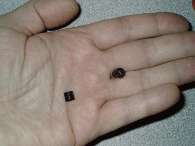
Update 3/24/15
I posted an ad on Craigslist looking for Borosilicate tube and got a response today regarding a tube - it was a very general reply from a glass blower - the quote was "approx $70" plus shipping. In comparison the mfg has a price of $130 approx. I was hoping for a more subsrtantial savings from a local glass supplier.
I found some online photos of ISI SR-50 which looks very similar to my own ISI SX-30. I see 2ea SR-50s photos online (blue and beige color) each one with different options installed. One has motorized stage movement and one has other options such as digital image capture. It looks like the same basic chasis and parts as my own microscope. The blue color and add-ons and larger crt monitor picture tube are small changes to make it modern. I see a product summary of a ISI SR-50 which has the text in a diiferent language - I dont know that language - the number 100.000 is I suppose the magification. I also suppose that various options can be installed to increase decrease magnification etc. I have included here 2 photos of these SR-50 microscopes (not mine) If the reader has any manuals, schematics, parts, tec related to the SR-50 - I would like to have those. Some of which are probably very applicable to my own ISI SX-30 as they are quite similar in design - that is my hunch.
There are some steel panels missing from my SX-30 - especially behind the column. As I look at the SR50 photos online - I can see a white metal box directly behind the column. My hunch is that very same box design is what I need for my SEM. If the reader can sell me these missing panels - let me know. My hunch is tat there are several models of ISI ABT or other brand model(s) which have alot of parts in common. This is especially helpful as I have a few parts missing - applicable to many models makes me hopeful in someday finding these parts.
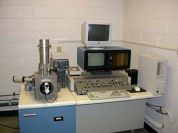
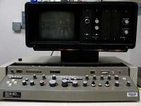
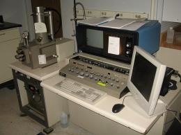
Update 5/7/15
I have located my 5ea VERY DUSTY but non-rusty steel panels for my ISI SX-30 and are indoors in normal temperature controlled conditions just the same as my SX-30 so these parts have been safe since I got them. I have one orange front panel mounted on the front of the SEM - so that makes 6 total panels. I was glad to see that I have the horizontal panel that goes over the raise/lower platform for the column (square-ish panel with a square-ish cutout for the column and its' cube/box). I am also glad to see more panels than I remember - I thought I just had a couple of panels - but I actually have 5ea. I see pictures of a beige box which goes directly behind the column of other ISI SX series microscopes. I am missing this steel cube/box. I have a metal forming workshop with finger brakes and nibblers and so forth so- I can fabricate a box of my own ... later. Right now I am trying to come up with winter bills which Im behind.
Also I have been working with a photoshop-like software "GIMP 2.6" which I have been using to compress my website pics and camer pics before posting - which makes the webpage load faster and better. My camera is an oldie and makes files approx 1-2 megabytes in file size. I was using Photoshop 5 but then my hard drive crashed and then had to reload everything in 2014 approx. I was without Photoshop 5.0 for awhile since I was always wondering if that is what caused it to crash in the first place - as it was acting funny in Windows XP and closing unexpectedly sometimes losing my work or just hanging/locking up. I downloaded GIMP freeware and is almost nearly identical in function with a few odd placements of buttons or menus here and there but for the most part it is nearly alike. One REALLY good feature is the ability to load and save a photo in any file format (I usually use JPG) and it has a slider (Photoshop has this too) for specifying the compression ratio of a file. I remember setting "3" in Photoshop with very little JPG noise I could get down to a very small file size. WIth GIMP I have been using "45" but I suppose I could go down further still but even so it is drastically much more efficient than what comes out of my camera. I see a noticeable loading difference on the pages I worked on - compressing the existing images. I see no quality difference before and after - it just loads a whole lot faster now.
When I visit various websites - it is very obvious that webmasters leave their photos uncompressed and 2meg-4meg-10meg etc files loading for just an ordinary photo - that is a waste of time for viewers. Use JPEG or JPG compression in GIMP or Photoshop. Its so much better when it loads faster ! Im still not done compressing all of the photos on my website. Im working on it as I have time. It seems like there was a lull for a few months - with no postings - but actually I was working - compressing files and then re-uploading the compressed version of the picture.
I found a Phillips Ambilight 42" plasma TV on the curbside 2-3 years ago replace the broken screen with a $25 Craigslist screen which I drove 35 mile to pickup (a guy in a limosine who met me in a Hrbor freight parking lot) and I fixed this tv and I actually never use it - you can see the edge of the ambilight on the left side of he screen. Also pictured is a 19" professional audio/video rack which is over 80+inches tall and I plan on cutting it with a plasma cutter to shorten it and welding it together again and then adding casters so I can roll it room-to-room or put it in the hallway sometimes. I got projects stacking up - basically. The plasma TV I also didnt want to run for everyday use - until I mount some cooling fans in it. I have the fans, plasma cutter, welder, panels etc. But I have winter bills and customer orders which take take priority. I always finish what I start. Im a finisher of projects. I have completed alot of projects, inventions, self-made tools, plans etc - just see the enormous quantity of links on the top of this page. I'll finish it - dont worry. The main thing is these things are safe and preserved from those who would carelessly toss it in the dumpster.
I have been communicating with a person in response to my Craigslist advertisement looking for ISI SX-30 parts (or other models as they may have similar or interchangeable parts)
This person works at a company that deals in tools and their ISI SX-25 no longer functions and they were willingto sell parts or the whole thing. I have been inquiring about their price and asked them to send photos.
I personally have never seen any SEM microscope (except my own) - but I have seen photos online of various microscope models and brands. But I have never seen any photos pf SX-25 model. It is interesting that the camera attaches to the built-in monitor and scans the image from the actual viewscreen. The column is very tall - like my own column. The base of the columns - Im goingto call that the sample chamber - the sample chamber is a completely different shape than my own. Also this SX-25 has a flip open cover for the console knobs. Ive seen some ISI SX- models with or without this flip open cover - so I really dont know if my SX-30 is mising this or not.
Another interesting thing is the rear of the column - does not have a big metal case. Instead it has an "H" shaped cover - for lack of a better word. Which allows the column's thick electrical wire to go through. SO maybe my own SX-30 didnt have a big box there - maybe it had a "H-shaped cover" as Im calling it - it probably has a much better name - and certainly doesnt resemble a letter H at all. Anyhow, these photos are wonderful. I have blanked out that which I feel is not applicable to the microscope and things like a vacuum cleaner and computyer consoles in the background - were Photoshopped out - by me.
The SX-25 has a Robinson Backscatter detector - as far as I know. I dont know if that is the correct name or term. But as I learn about these things- I run the risk of opening my mouth / writng something incorrect. No problemo.
I am trying to acquire parts and pieces and books etc. Its not clear to me what they are willing to sell and they have not stated a price. Its very vague. Hopefuly this machine wont end up as scrap.
I have a wild guess as to what happened - regard why it doesnt work anymore - I see an electricl outlet - probably 120V and the ISI SX series of SEM microscopes are 100VAC - so they require a stepdown transformer. It is not clear whether they have on or not. It is my hunch they attempted to run it at 120V. My wild guess could be wrong - maybe they actually have a transformer - I need one.
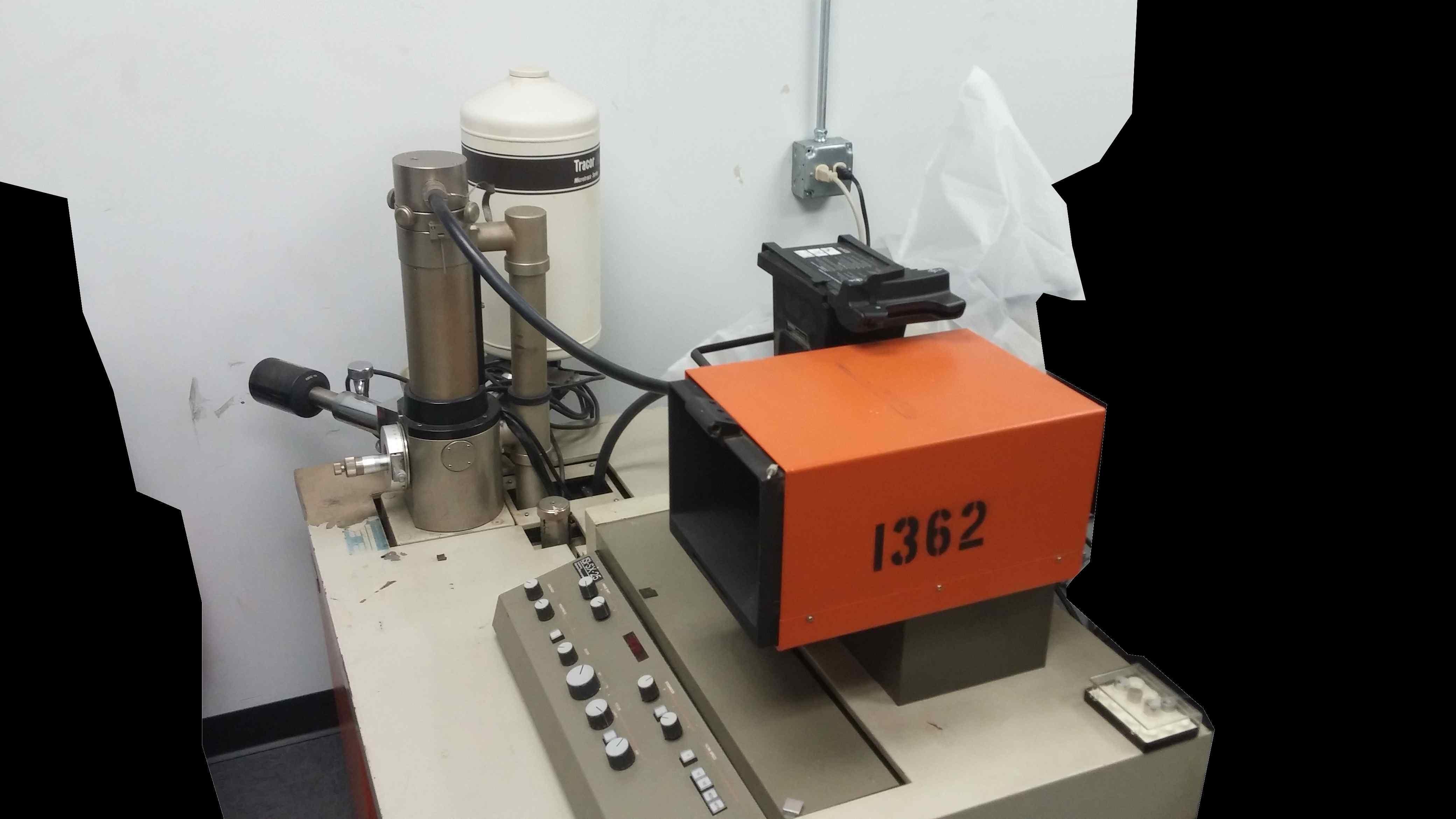
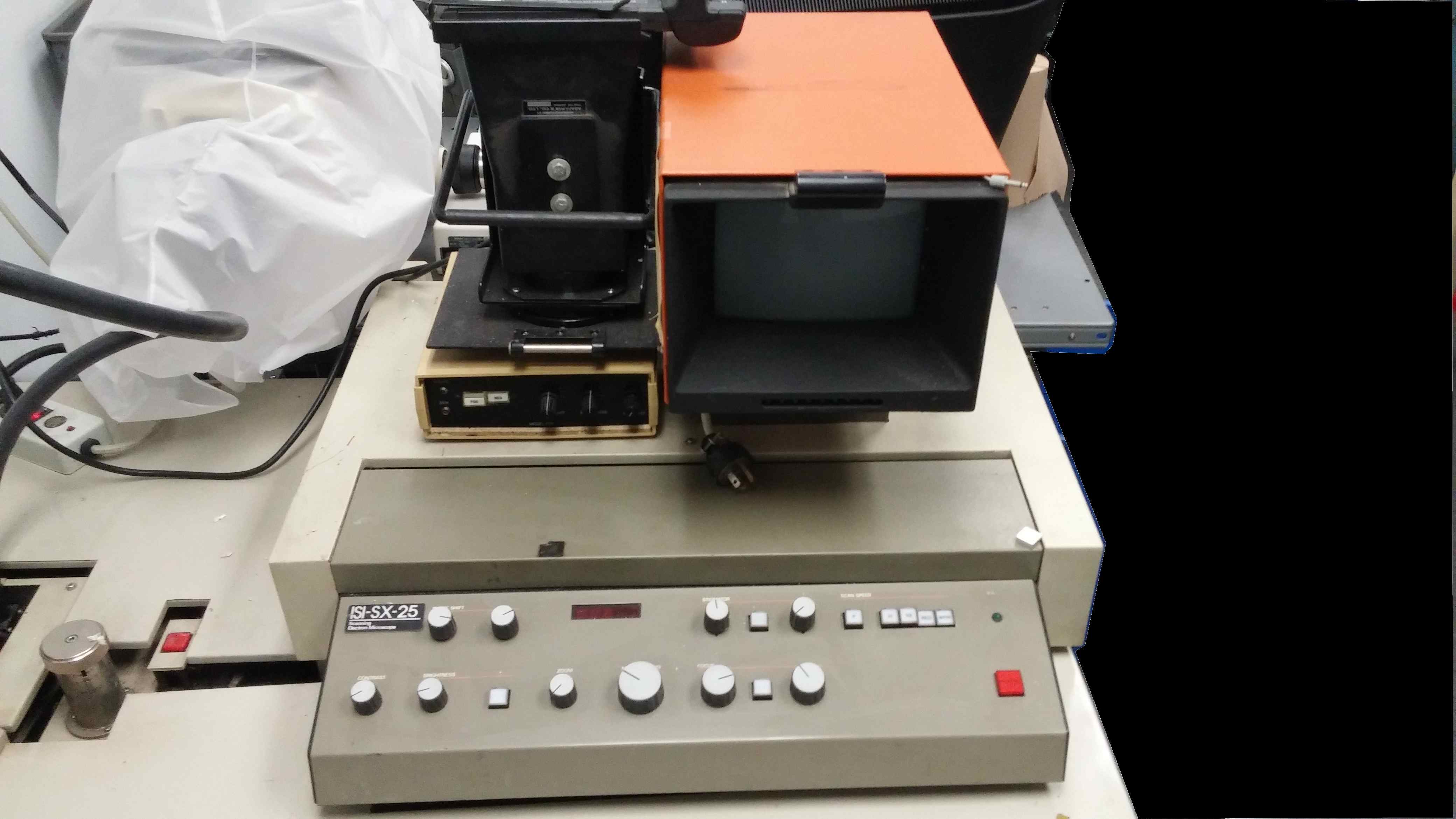
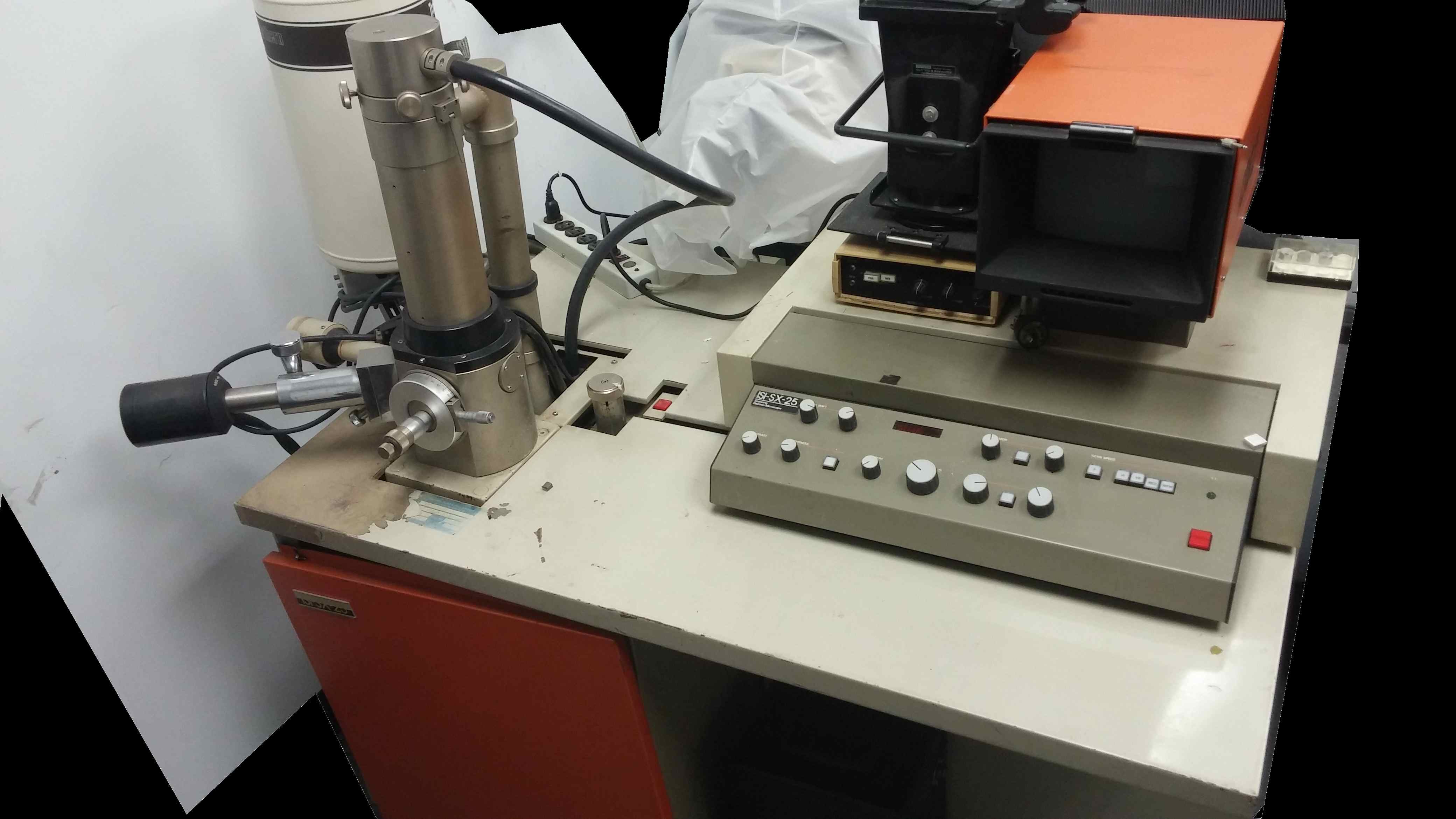
I placed a Craigslist ad for many months seeking to buy a 55 or 50 gallon oil drum for burning leaves. Some sellers wanted too high price, some too far away etc. I purchased 2ea oil drums (actually has an orange juice concentrate sticker on the side) which were in very good condition except missing lids and one had several big dents. The seller wanted $35 for 1 or $45 for both (one had major dents so was cheaper) delivered. So I purchased 2 and the extra one I will use for my SEM microscope water collection. The SEM requires water cooling from a sink or piped in cooled water. I would say that some SEM owners also use water chillers or just let tap water run (I dont want to waste water or have high water bills). Both of those are too expensive and my funds are limited.
My thoughts are to use a long hose from my sink to the SEM and then have it discharge heated water into the 55 gallon barrel drum. Then when it is full - I will pump it into my toilet and reuse the water at a later date - so that water is not wasted.
Here are some photos of the drum that is the best one out of the 2. I painted the bottom/top portion with Rustoleum brownish/gray paint and several paint brushes. The outside is naturally green and the inside is naturally brown. It was an FDA food container in its previous life - concentrated orange juice - 55 gallons is a whole lotta orange juice concentrate - and even more when you add water!!! I kept the sticker on the drum as a souvenir LOL
I need to buy some caulk as I plan on caulking the inside rim and outside rim of the bottom. And also caulk the outside rim of the top lip. Im sure it doesnt leak. But I just dont want 55 gallons of water leaking out now or years later. So I will prevent rust by sanding/painting those areas - then caulking.
The photos of the top and bottom - I already sanded and painted and these photos show it drying outside. I still have to do the sanding and caulking of the inside and outside rim. See whaty I mean about improvising? Sometimes I have to.
I once worked at a local plastics company where a man had 5 big plastic injection molders in his 3-bay garage. He later moved his small business to a real warehouse and I was working for his during that time. As he was transistioning and were moving his mult-ton mahines with heavy equipment - he used plastic barrels full of water that would be changed out a few times a day. He pumped water from the barrels into his plastic injection molders to cool the mold and solify the part. Im basing my SEM microscope water cooling barrels on that. Water cooling in the wintertime has a natural positive effect if I move the barrels outside - nature will cool the water. Of course if it freezes the barrel will bust from the ice. Im still figuring it out. For now Im just working on the barrel and making it neat painted and waterproof. Ill figure the rest out as I get further along.
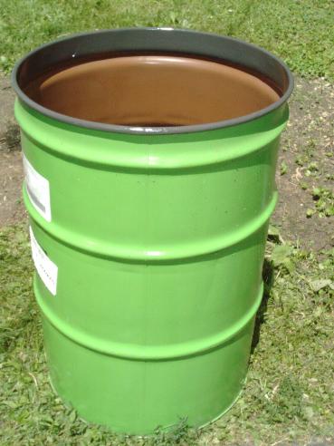
Here is a picture of the bottom of the freshly painted drum you can click to view
|
|
Microscope Barrel2.JPG Size : 841.257 Kb Type : JPG |
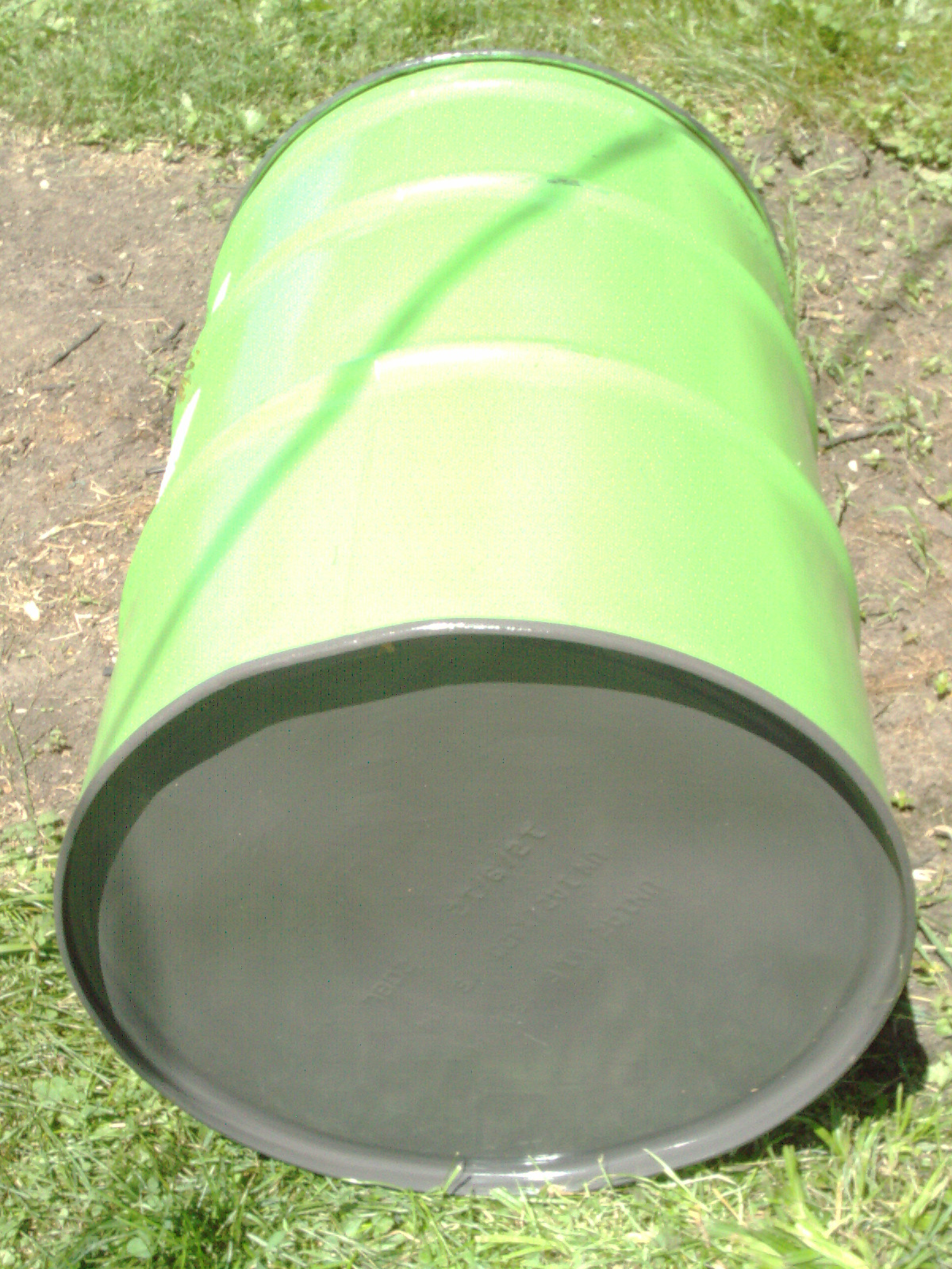
I have thoroughly cleaned and painted the barrel - all done with painting now. I flushed out the inside with water. I feel it is as clean and safe from bugs etc as I can make it. I sealed the edges with Rustoleum paint. I painted it over a few days using several disposable small brushes so I can turn it over and paint each section carefully and then let dry etc one section at-a-time. I will leave the caulking part until later as my funds are low at this time.
It is now located indoors in the wall corner next to my SEM microscope.
Update 7/27/15
About a week ago a person from a university made a general inquiry on what he should do with the university SX-30 (implied that it doesnt work but was very brief ambiguous inquiry.) Here are 2 photos of that unit. It looks very similar to my own unit. I wrote a long response to that short inquiry - to summarize I said dont let it go into a landfill and only part it out as a last resort. It is better to keep it whole and find someone locally hobbyist/business/school etc or better yet fix it and continue to use it.
You would think that someone at a university or school would be surrounded by electronics teachers, students, technical staff. You would think that that machine would be serviced by some knowledgeable person there. Instead - they are speculating on its demise. What a waste of a wonderful machine. As most electronics failures go - there is a $1-20 part in there that has dies and it is just a metter of figuring out which part needs replacing.
My microscope is a keeper. Even though my my finances are limited I continue to add to my collection and parts for it and someday I will have it up and running.
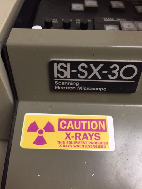
I have looked several times in 6 months hoping to find a 6amp circuit breaker which I like and of decent quality and decent condition. 6amps is hard to find in a used circuit breaker and the few I have found - I made a bid or offer and was turned down. I had to pass on several due to the higher-than-I-wanted-to-pay price. So I spent many hours searching online unsuccessfully.
Today I went on an online shopping spree and spent $18 including shipping for the following items
A) 4ea 2mm banana jacks (binding posts) - only needed 3 but came in pairs
B) 1ea Mechanical Products 6amp Circuit Breaker
C) 3ea CMS magnets with thread and neodymium magnet surrounded by steel with plastic gap ring
The above items are to finally replace the previous owner's boogered up circuit breaker situation on the Anatech Hummer IV. I felt the used circuit breaker I selected is a very good replacement and as close to the original as I can afford. Functionally equal to the ETA in my opinion. I passed on several which were too expensive or didnt have a number printed on the pushbutton. This one is smaller than the original and is white with black printed number. The original was most likely a black button with white printed number. Otherwise it is electrically equal.
The 3ea banana jacks and magnets are for my homebrew sputtering target which I will remove the plastic from the banana jacks and use them to attach a homemade aluminum plate to the existing 2mm banana plugs in the sputtering flip-top head. I will secure these banana jacks using 3 punched holes in the round aluminum plate (yet to be made) and secured with the nuts that were included. This will allow a small amount of wiggle room in the punched holes - for perfect alignment with existing banana plugs.
I plan on using the 3ea CMS magnets with thread to hang down from the round plate - over the specimens. After studying some homemade sputtering units that youtubers demonstrated - I noticed that the gap between the outer magnets and the inner magnets is where the glow comes from - in those youtube homebrew units. I believe that the CMS magnets will have a similar gap due to the outer steel case and the inner neodymium magnet - the ring in between is the part that will glow. The 3ea magnets I selected came to approx $6.80 and are just larger than a 1cent penny. This side will just fit over a specimen. I decided to use small magnets as I can try various small materials such as aluminum foil, gold foil, etc and not waste too much materials in case something doesnt work well. I can add more magnets or larger magnets later if need be. Specimens are small so why have a large sputtering target and spray material everywhere?
Gizmos and inventions and gadgetry is very expensive and even though I am saving greatly over buying a new sputtering target- its just handful of components - compare that to buying a used tv set or laptop computer- which are filled with thousands of components. Buying individual components - very expensive.
My Hummer IV repair will end up costing several hundred bucks in misc small parts - but I look forward to having a working sputter coater and SEM someday.
Here are some pics from my $18 shopping spree (still high but the best I could do)
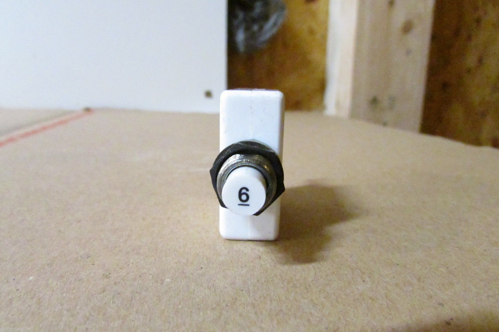
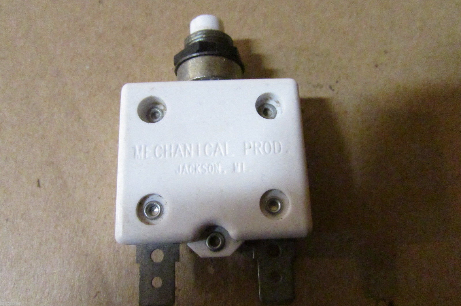
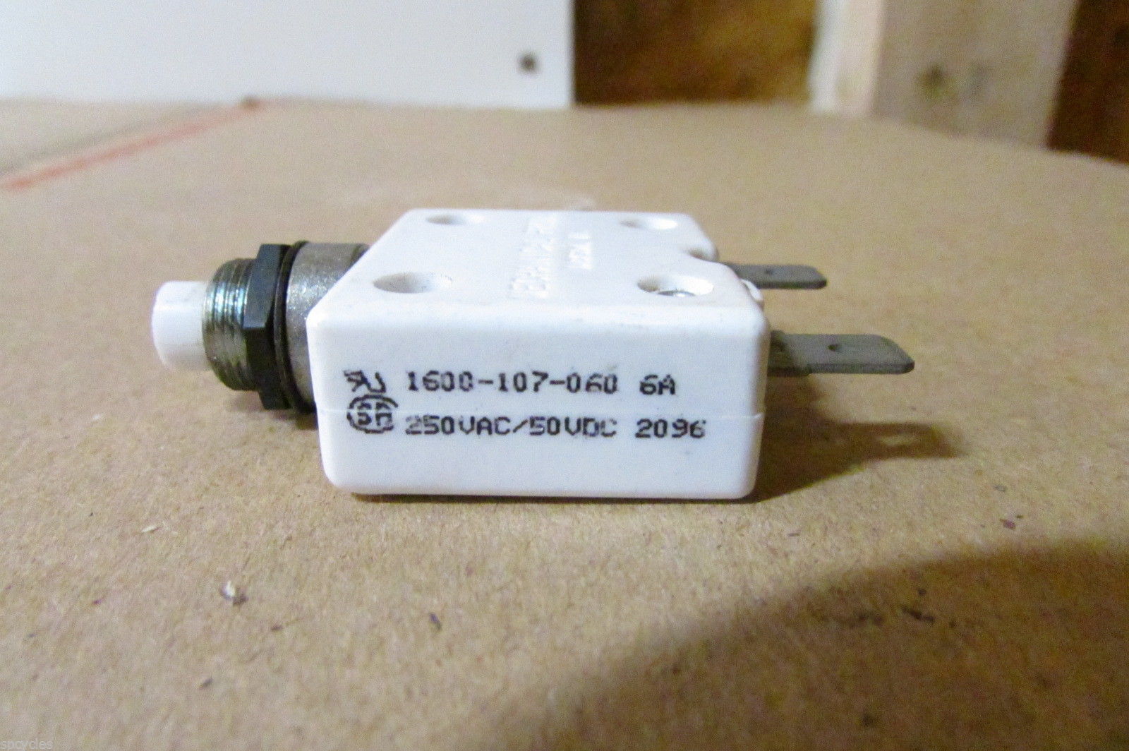
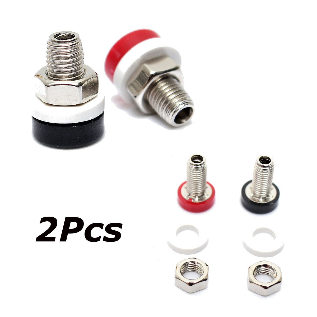
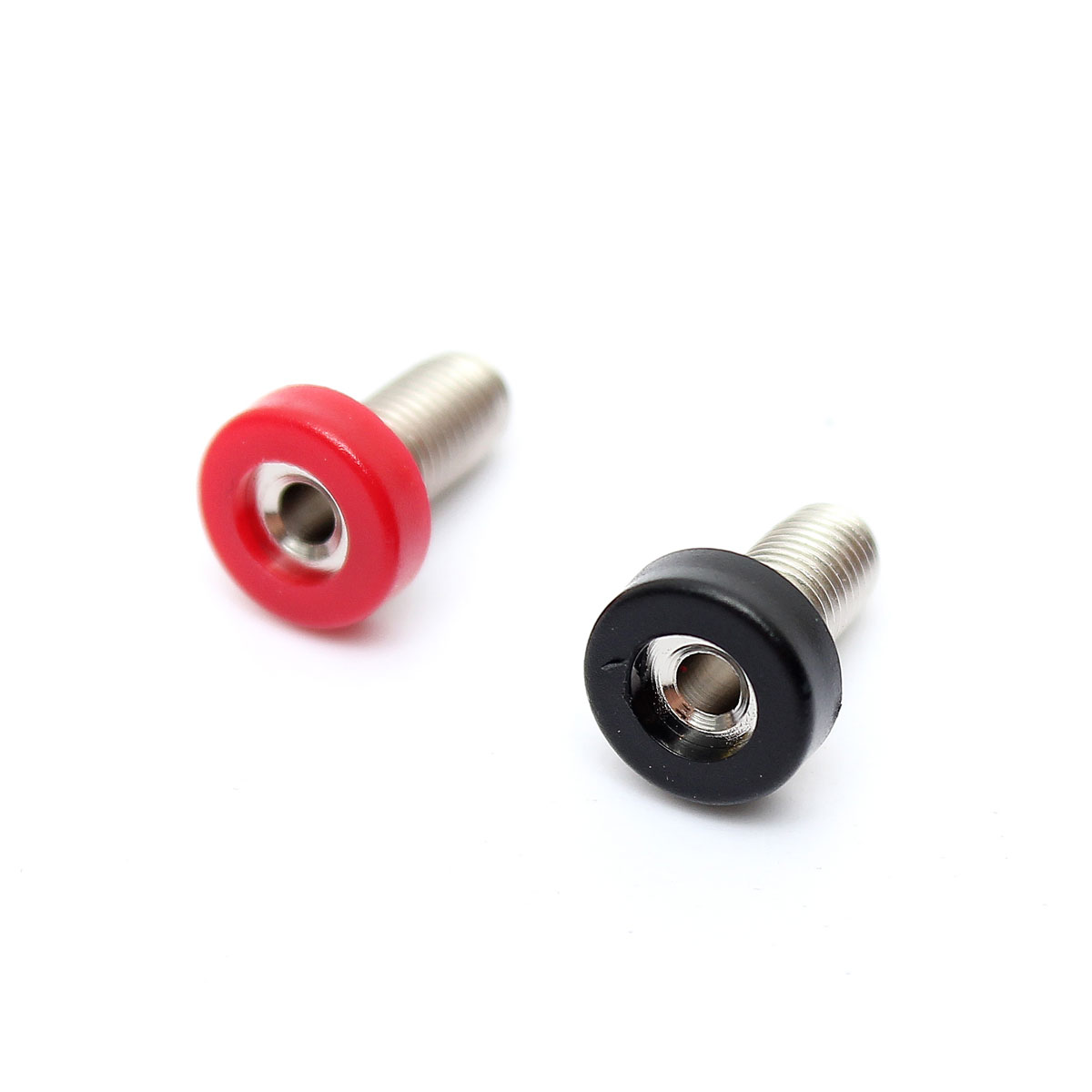
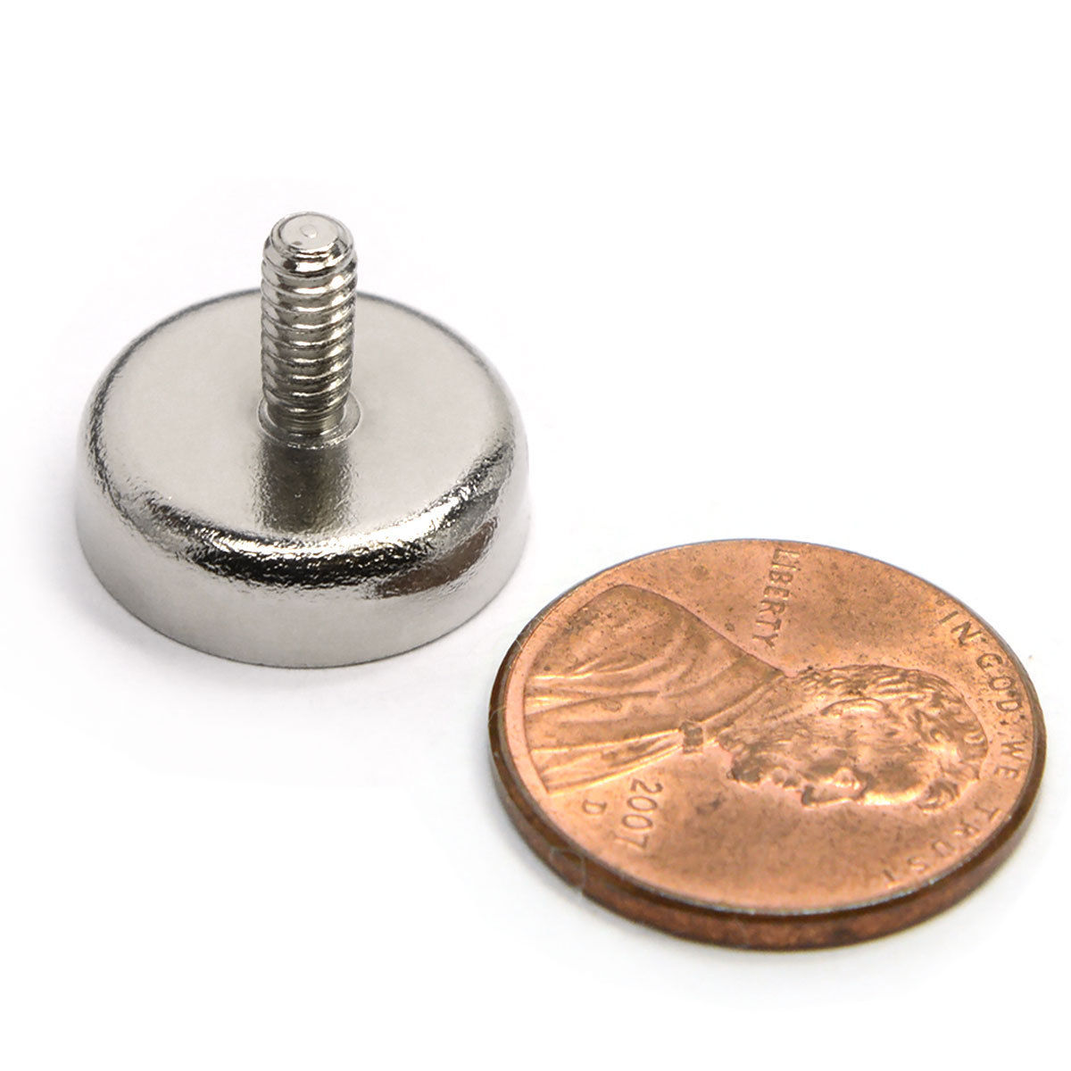
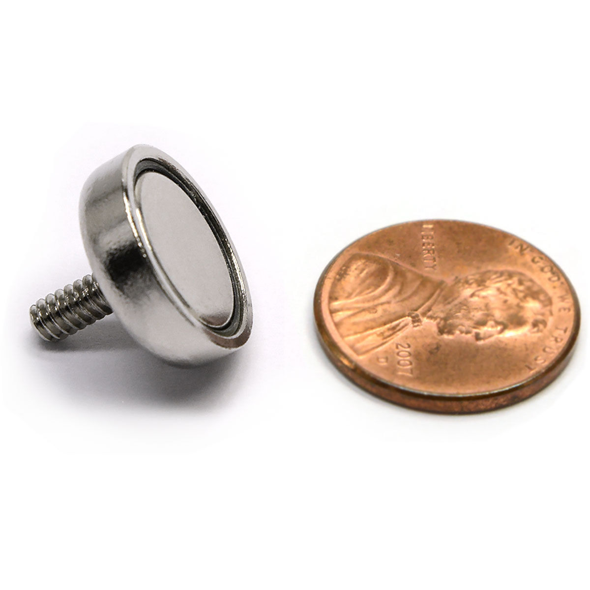
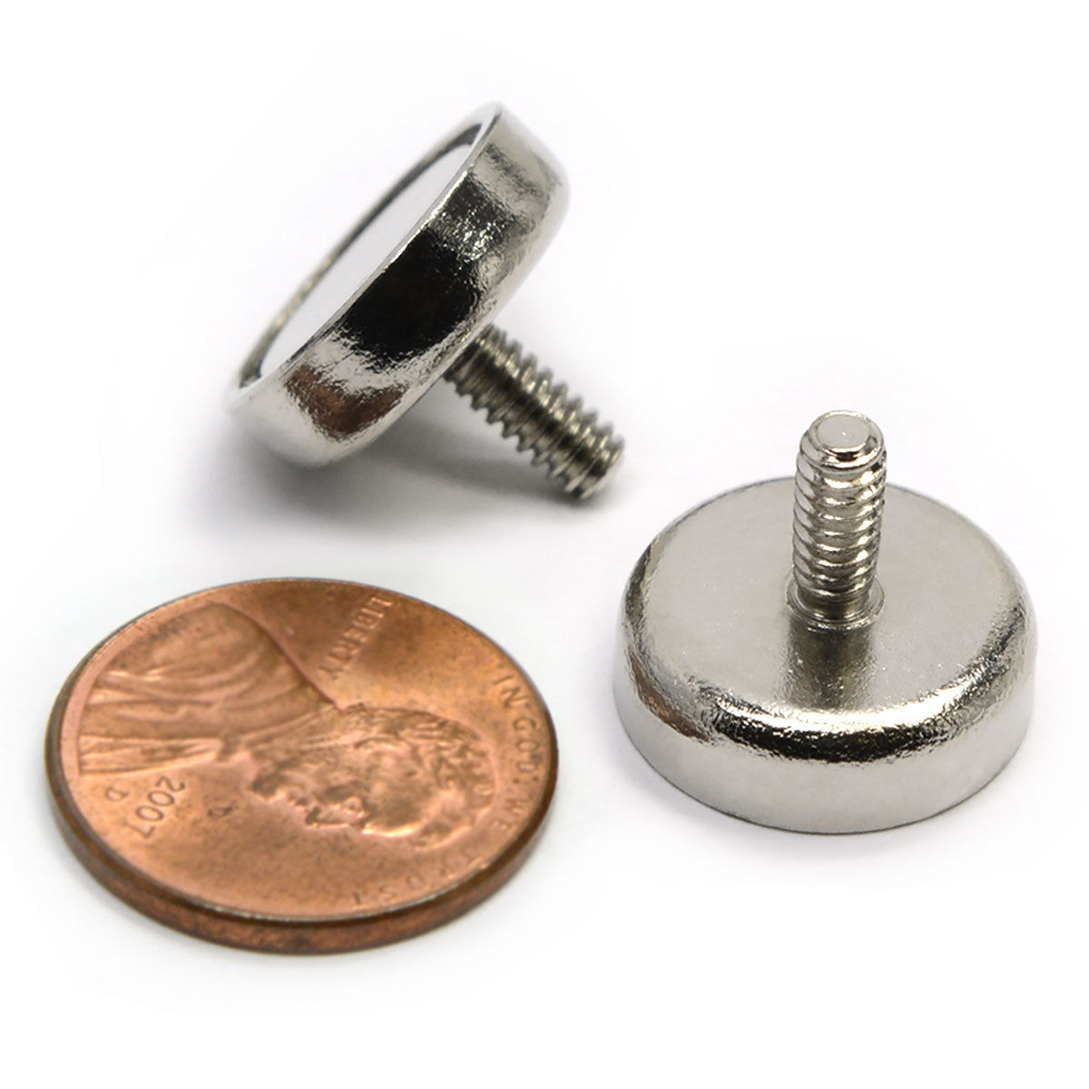
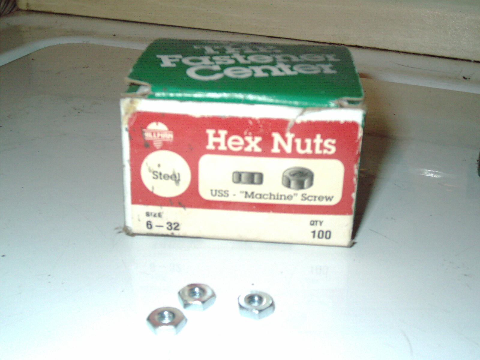
I have received 3ea CMS magnets with threaded rod end - today in the mail. They are very nicely nickel plated. After looking through my inventory of misc nuts, bolts, screws etc I found a box of Hillman 6-32" hex nuts which were purchased from Ace Hardware about 8 years ago for another project and I had some leftover (Hardware stores sell these individually or by the box). The 6-32" nuts are steel and thread very nicely onto the CMS magnet's threaded end. I have temporarily stuck the 3ea magnets onto my refrigerator. I have to remove a CRT monitor which is on my Sputter Coater workbench right now before I can put the magnets anywhere near my Hummer Sputter coater. These magnets are SO VERY STRONG that it would be a BIG MISTAKE to place them anywhere near a CRT TV or monitor as the magnet will permenently ruin a CRT monitors screen and make a color swirl discoloration which is very hard to fully and precisely correct without a degausing coil. I once bought a brand new 20" CRT TV from a retailer big store (that was current technology at that time) in the 1990s wth a very small blemish on the upper left hand corner (color swirl discoloration - blue solid video screen had yelloy at that corner for example) and they reduced the display model price by $50 so I bought it. That small discoloration was VERY DIFFICULT to fully remove and still had a leftover discoloration even after I improved it as much as I could. Only 10 years later is that discoloration fully gone- TV degauses itself very slightly each time you turn it on with a built-in weak degausing coil. It wasnt worth the $50 discount. I dont want to make the mistake of putting these magnets anywhere near a TV set - so I have to reorganize my workbench and move a crt moniitor somewhere else - as a CRT monitor next to a sputter coater with a DIY sputtering target using powerful magnets is a very bad idea for the safety of the crt picture tube. Magnets stuck to my refrigerator is a nice safe place for now.
here is a youtube video (not my video) showing degausing a TV screen which was ruined by a magnet (dont do this).
https://www.youtube.com/watch?v=3pVLizAHby4
At this time I also have received the Mechanical Products (a few days ago) 6 amp circuit breaker and tested it on my multimeter and it shows conductivity which means it is a good circuit breaker. Physically it looks in very good condition for a used product and feel I got a good one. The only hiccup in ordering this as a replacement is the hole for the E-T-A original circuit breaker is smaller than the hole required for the Mechanical Products circuit breaker. So that means I will need to punch or drill or ream-out a larger hole in the panel.
The banana jacks have not arrived yet. I should point out that the pennies in the photos are there just for size comparison - I dont intend to do anything with pennies.
Update 3/26/16
I received the 4ea mini banana jacks today and unfortunately the hole is too small and doesnt fit over the 3ea banana plugs in the sputtering head. I will have to come up with a solution to this problem.
I used an online metric to Inches calculator which shows 2mm = 0.0787402" that is the hole size in the banana jacks I received.
I measured the 3ea Mini Banana plugs in the sputtering head and estimate it to need a .087" to .093" hole for a snug fit.
The solution will be to slightly drill out the jacks to have a tiny bit bigger hole.
I researched online to see if there exists a slightly larger diameter mini banana jack and only found the same or larger (2.7mm, 3mm, 4mm all are much too large diameter). So I need to improvise a solution. I have quite a lot of machinist reamers but I dont have anything close to this mini size. I may just use a drill bit or diamond Dremel bit mounted in my lathe and work it back and forth inside the jack as the China mini 2mm Banana Jacks are only made of brass with a nickel plating and is not a hardened metal. Ill look through my drill bits and other bits to see what I have that can ream or drill out the hole with the least scarring as possible. Ideally the bore hole should be nice and smooth with a snug press fit over the banana plug.
While measuring my sputtering head - I noticed one of the banana plugs wiggles and the other 2 are firm.
I referred to a drill bit chart and #43 drill bit is .0890" diameter approx and would in actual practice drillout a larger diameter hole than the book. As I looked through my collection of drill bits and reamers - I dont have that one and will need to buy one. I see a few imported #43 .0890" or .089" hand hss reamers at approx $5-8 on big-auction-site and will make a nice clean bore with exact size - whereas a drill bit will make a rough hole on the inside bore - which would scratch/gouge up the sputtering head's 3ea banana plugs after a few insertions.
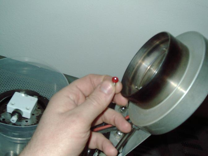
I have posted a picture of the 3 magnets which are currently stuck to my Amana Refrigerator/freezer. I have put them there as I dont want to accidently put these by a crt TV screen or other sensitve unit. For now they make good refrigerator magnets - I put some paper between the refrigerator door and the magnets to avoid potentially scarring/denting the plastic texture covered door. Im currently catching up on bills/trimming trees and summertime property maintenance/repairs so I havent been able to spend time or money on the SEM project for awhile.
Unfortunately the seller of the ISI transformer on big-auction-site renigged ater I won it/bought it and decided to dispose of it. The auction said he had 2 for sale and I won 1ea for $75 but received nothing except a refund. Thats too bad as I am missing the transformer. I hope a reader has an extra one for sale.
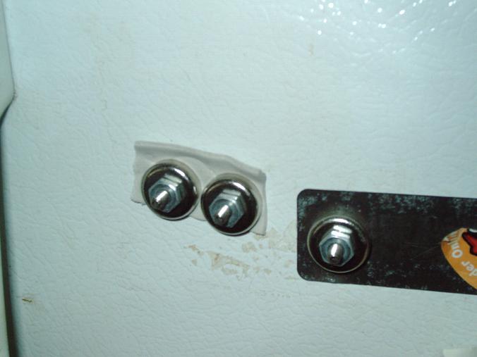
I received an email from a seller who scrapped his ISI SX30 a couple of years ago and held onto some parts. I have included some photos here in this zip file. A summary of contents, roughing pump, oil diffusion pump, caster wheels, step down transformer, filaments, Secondary Electron parts and pieces, cords cables (some cut) showing cable/connector ends for transformer and roughig pump.
Having just purchased an expensive IC tester I was drooling over for years (purchased from India) and winter just coming into full force - this sellers email comes when my finances are at the lowest point in the year for me.
I have been searching for caster wheels for years - none of the sellers so far saved it while scrapping their machine. I have a broken caster wheel and I surely need that. My cat was in a fight and she is recovering in the SEM room. So I need to not disturb her too much (just started eating a little again after much coaxing) When she is recovered I plan on pulling my wonderful heavy SX30 from against my wall to make sure I have the same ports - as the seller.
I remember receiving some photos from international SEM owner and his SX machine looked totally different than mine did. So while seller is saying stuff like "of course the sx30 has a JS1 port" - I want to look and see - because there may be differences from year to year of the same model. Wouldnt it be wonderful to be able to buy everything - reality is that I need to be frugal and watch my money as money-is-tight right now.
Also the following zip file (contains pics of sellers parts which I am attempting to buy some in the near future) contains a picture of SX-30 transformer which has a date stamped on the side "1981" which gives me the approx years/era in which my own microscope existed. So now I know my SX-30 microscope is from the very early 1980s possibly as early as the late 1970s.
|
|
Sellers SX30 Parts 121316.zip Size : 7118.136 Kb Type : zip |
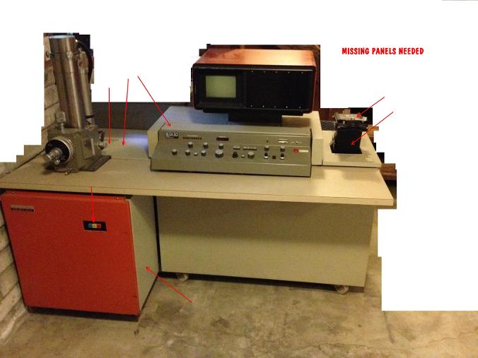
The above photo is not my SEM. I have drawn arrows on the steel panels that I am missing. Also my front Blue/Yellow/Red triple pushbutton switch is sticky ( I would like to replace it ) The above photo shows the beige flap door located just behind the console/ and directly below the monitor - this flap door is present on the above pictured SX-30. I am looking for this flap door, and other steel panels which I have drawn red arrows. It is too bad the seller scrapped the above SEM - it sure was pretty. I hope that I will find all of the parts I need. I currently am buying a single caster wheel from this seller (The above SEM is the donor unit long since destroyed 2 years ago) Im glad to put the parts to use to complete my own unit.
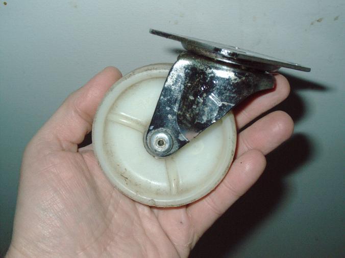
My used $20 caster from a seller who scrapped his ISI SX30 (see above photo) arrived today. Whew! Im so glad it arrived. A simple thing like a busted caster makes moving a 1000lb SEM a real problem. I sent the seller an extra $5 upon caster arrival.
Since yesterday I have tried to leverage up the SEM with a wooden stick - broken stick. I have a cat who fights with my newly adopted cat - I keep her separate in the SEM room. So Im waiting until she "cools off" from her aggressiveness. So in the meanwhile my caster is not installed - cat issues override my SEM repair. I have a few scraps of wood, aluminum lathe cutoffs and small metal block which I will try to improvise some "jackstands"
The highschool janitor busted my caster simply jacking up the SEM unevenly where the electrically powered/motorized pallette jack (fanciest one I have ever seen) lifted up the SEM where one wheel bore the entire weight of the SEM. It busted right in front of me 3 years ago.
NO ONE THAT PARTED OUT THEIR SEM SAVED THE CASTERS! So Im so glad the current seller saved 4 casters and at $10 each plus $10 shipping I bought one. He also kindly reponded to my email asking him if he saved a coffee can of screws for the side panels. He kindly included a small handful of screws in a ziplock bag - which I assume are for the steel panels. IM SO GLAD TO HAVE FOUND THESE PARTS.
The caster seems to be an exact match as I feel around to touch the leftover pieces of the caster down under there.
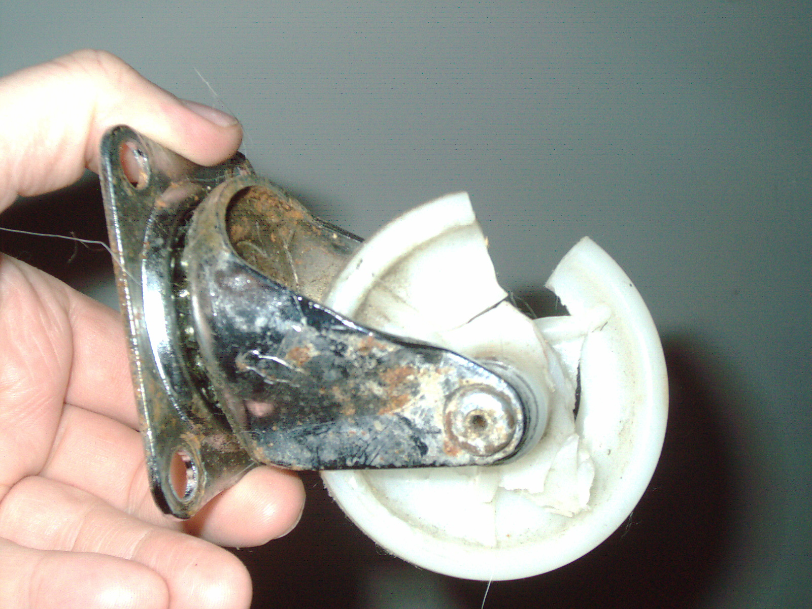
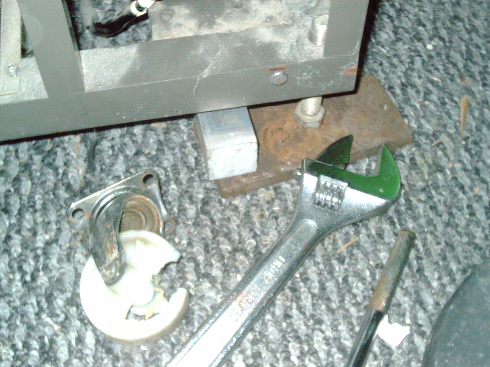
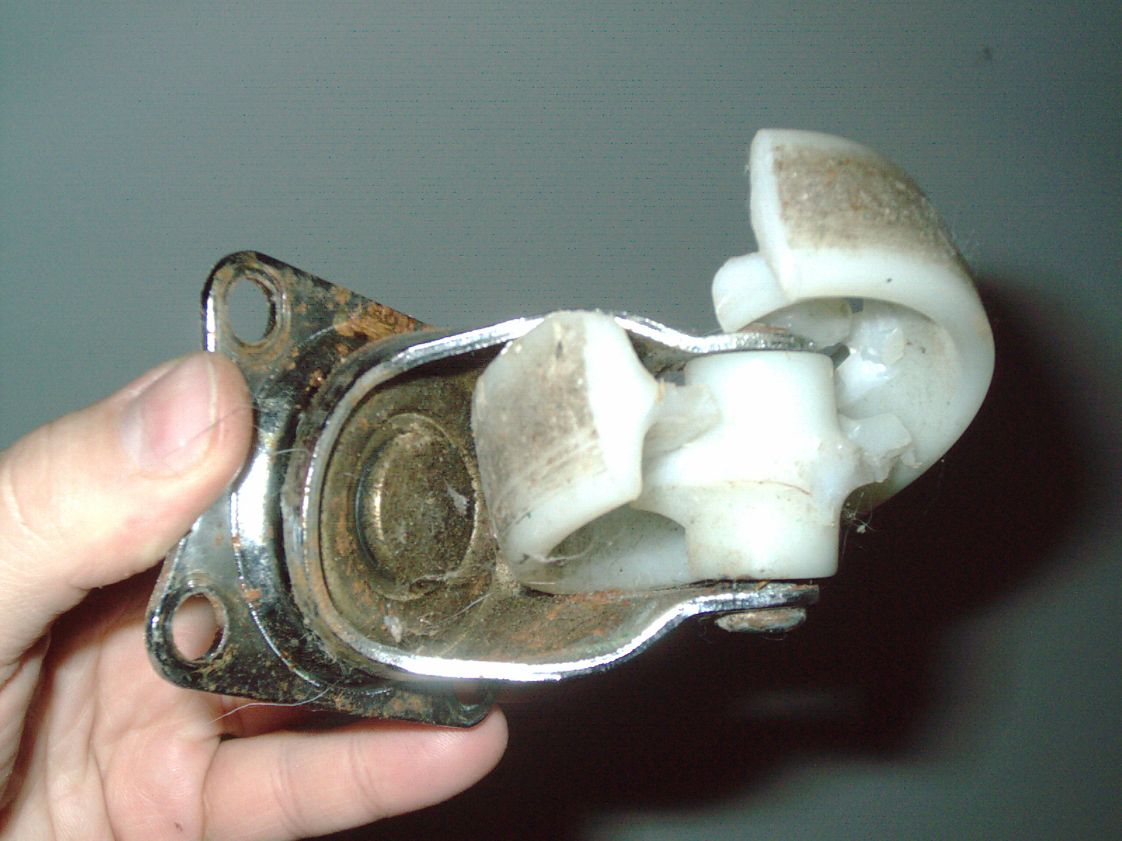
I put alot of thought into how I was going to change out that broken caster. I have a hydraulic 2-ton carjack - too tall. Crank up Diamond shaped car jack - also too tall. I tried using a piece of wood as a lever and the wood just shattered. The darn microscope weighs 1000lbs and is MUCH heavier than it looks. The best solution I came up with was to find a piece of steel scrap in my inventory and that is about a 3/8" x 6" x 3" plate. I put that metal plate under the built-in jackstands which are basically a welded nut to the frame and a LARGE bolt. So I found the biggest adjustable crescent wrench I have (my open end wrench set didnt have anything larger than 3/4") which I hardly use for anything and hardly a scratch on it- even though it is 15 years old. I only used it for bathroom repair so far. But it came in handy today as I used it to extend the ISI SEM's jackstand/bolt while resting on the steel plate. I strategically put aluminum cutoffs under the SEM frame - to prevent the possibility of the whole thing collapsing on me. I have included photos of the busted caster, and my solution to how to jack the SEM up.
As I was using the crescent wrench to extend the bolt/leg that bolt was really precarious and leaning substantially at times- making that whole machine tilt. Im so glad the welding didnt break or bolt bent. The incredible weight - you have to have been there to appreciate what Im talking about. The leg/bolt was like the Leaning Tower of Pisa. And when fully extended - straight as can be.
And just as a quick test after putting my tools away - I moved the SEM back and forth a couple of inches. Now it moves - no big deal. But with a broken caster and the weight distributed unevenly - the SEM was a bear to move with a broken caster.
Caster was held in by 4 bolts. The actual replacement of the caster was no big deal. I put the new and old caster back-to-back and side-to-side for comparison. It is an exact match.
My best professional hunch is that the caster wheel plastic is polyester or possibly a very hard nylon as it is a clean break and has a similar feel as Stratasys Genisys 3d printer wafer polyester cartridges. It probably the same as a plastic found in Kodak projectors for the variable transmission. A very hard brittle plastic which takes a load well but when it breaks it snaps. And this type of caster is typically 300lb each load capacity - there was no way for it to bear the 1000lb load all by itself when the school janitor jacked it up non-straight.
It was a simple but difficult problem. I could have easily cracked another caster - while replacing this one. Or toppled the SEM on its side. I was careful and put YEARS of thought into my solutions. Even so I cracked a piece of wood needlessly yesterday.
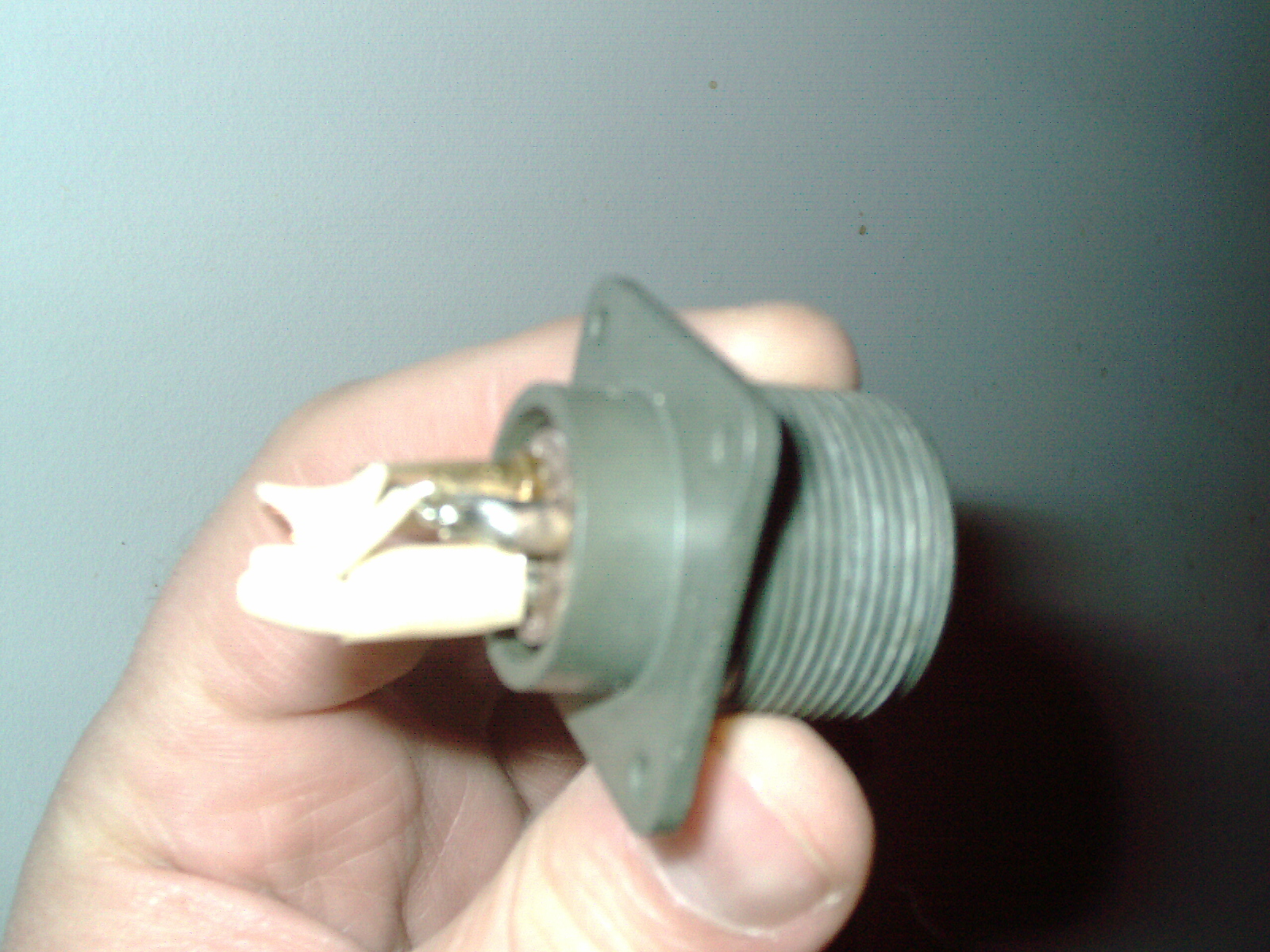
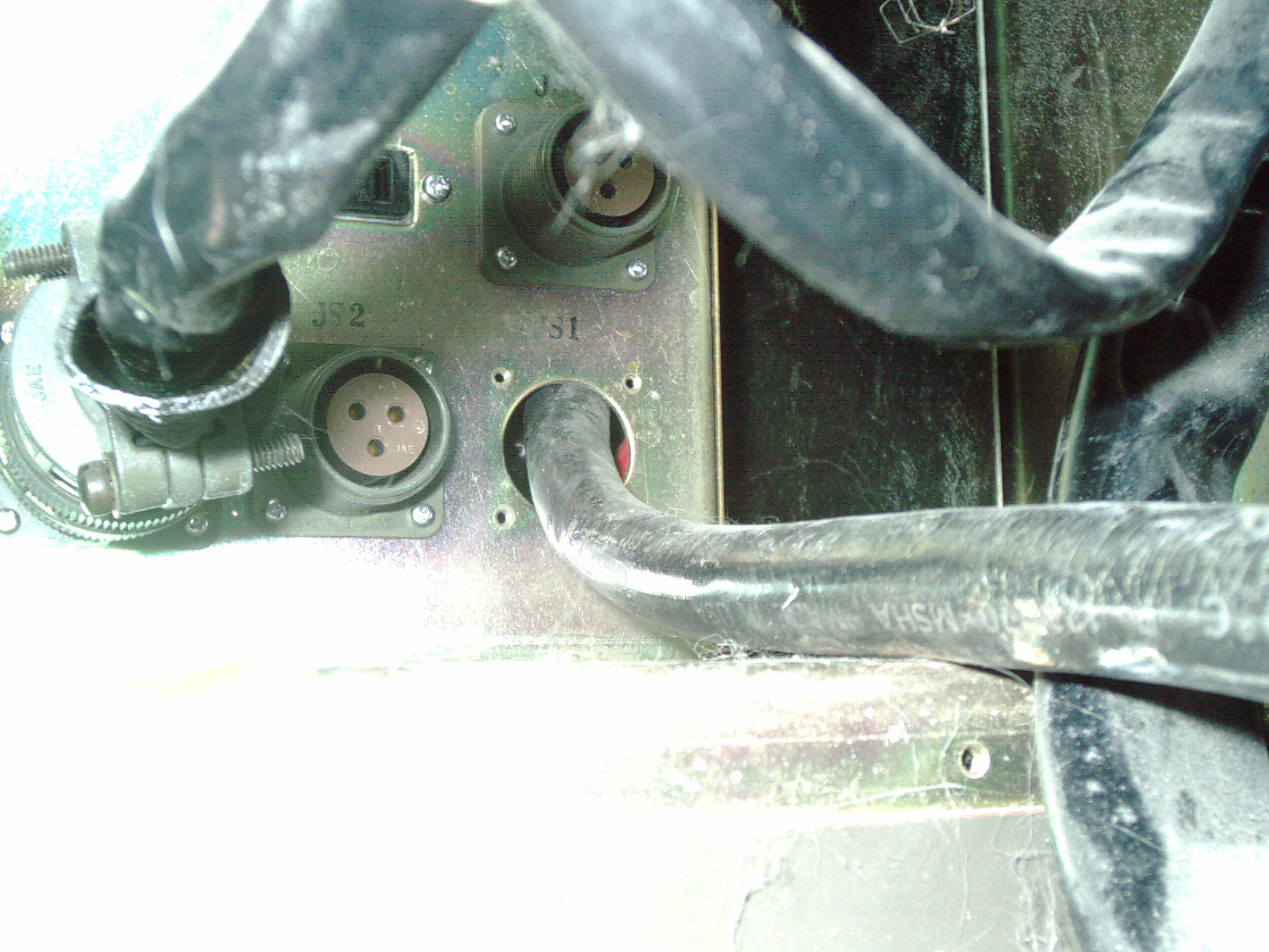
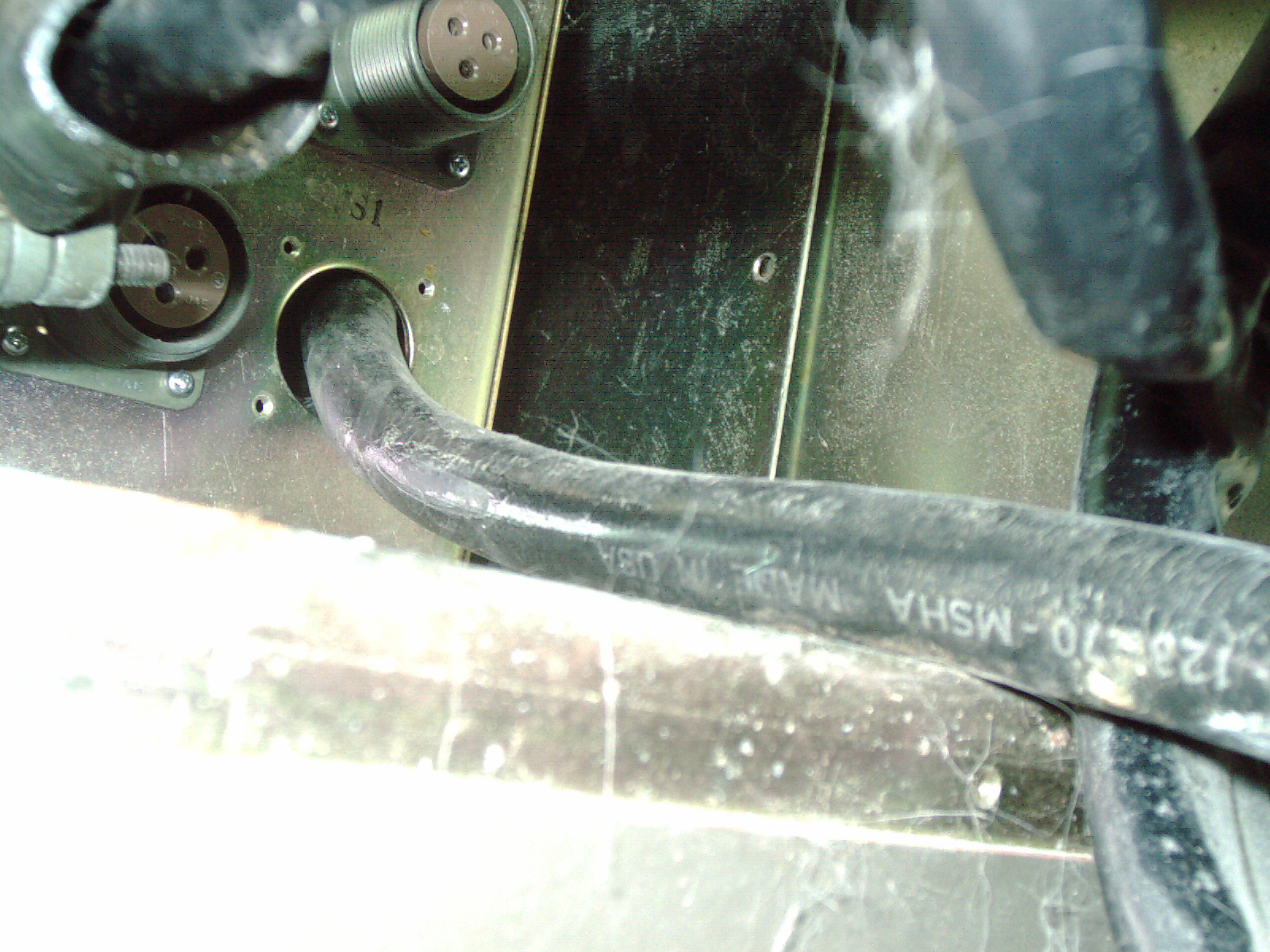
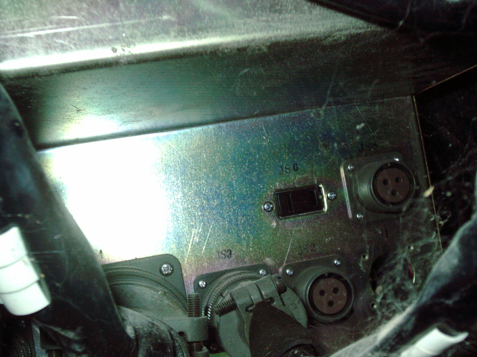
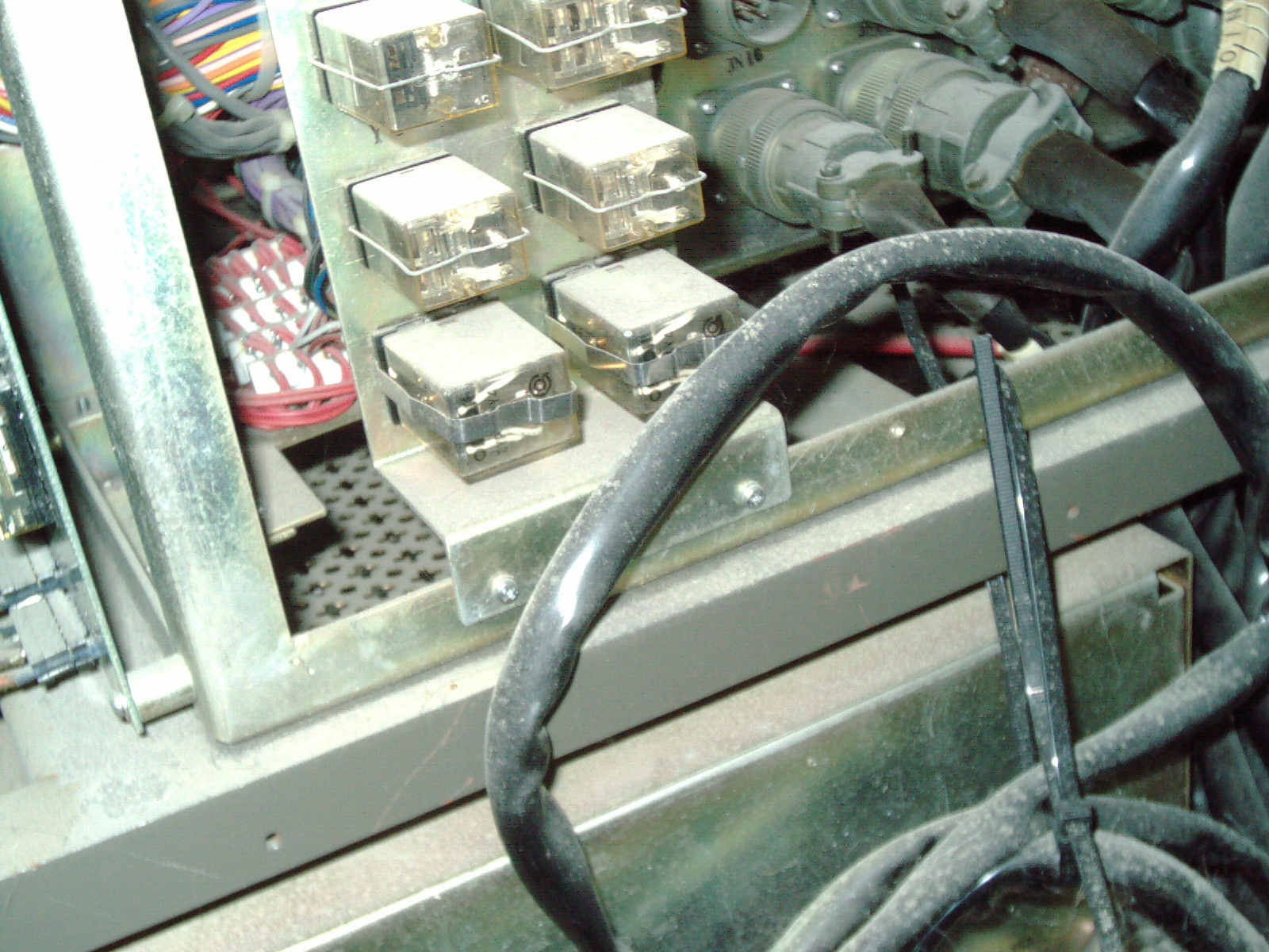
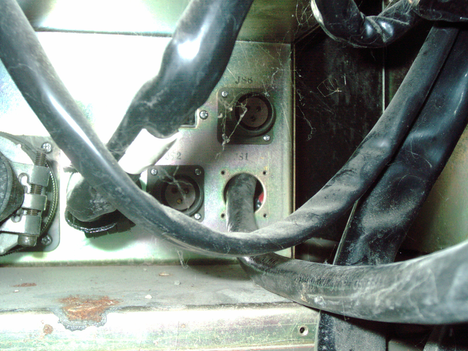
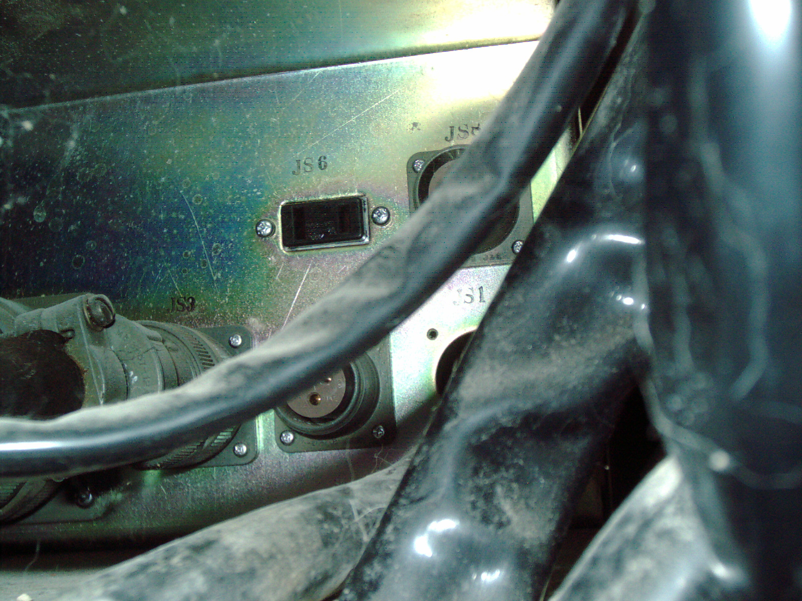
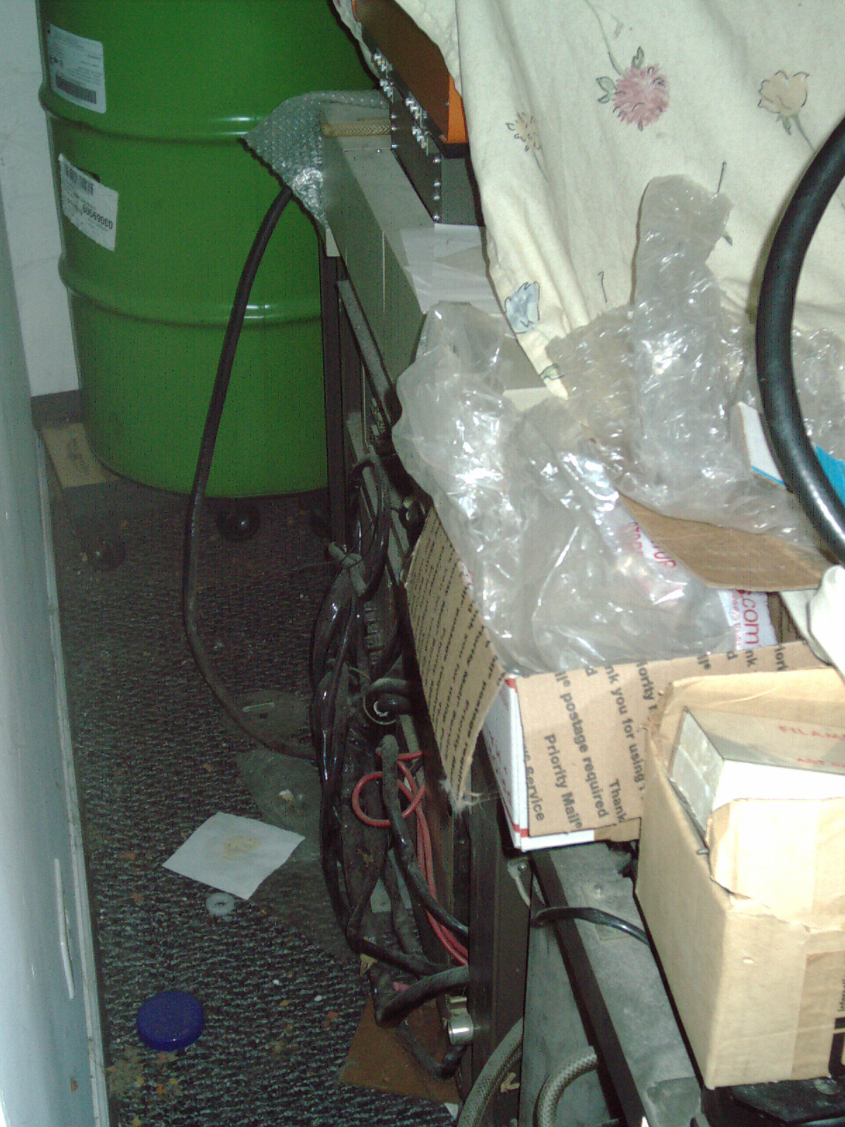
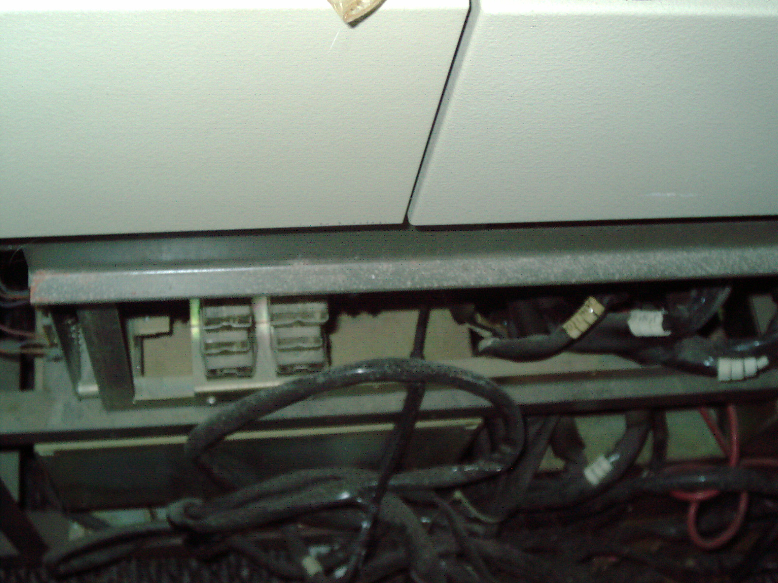
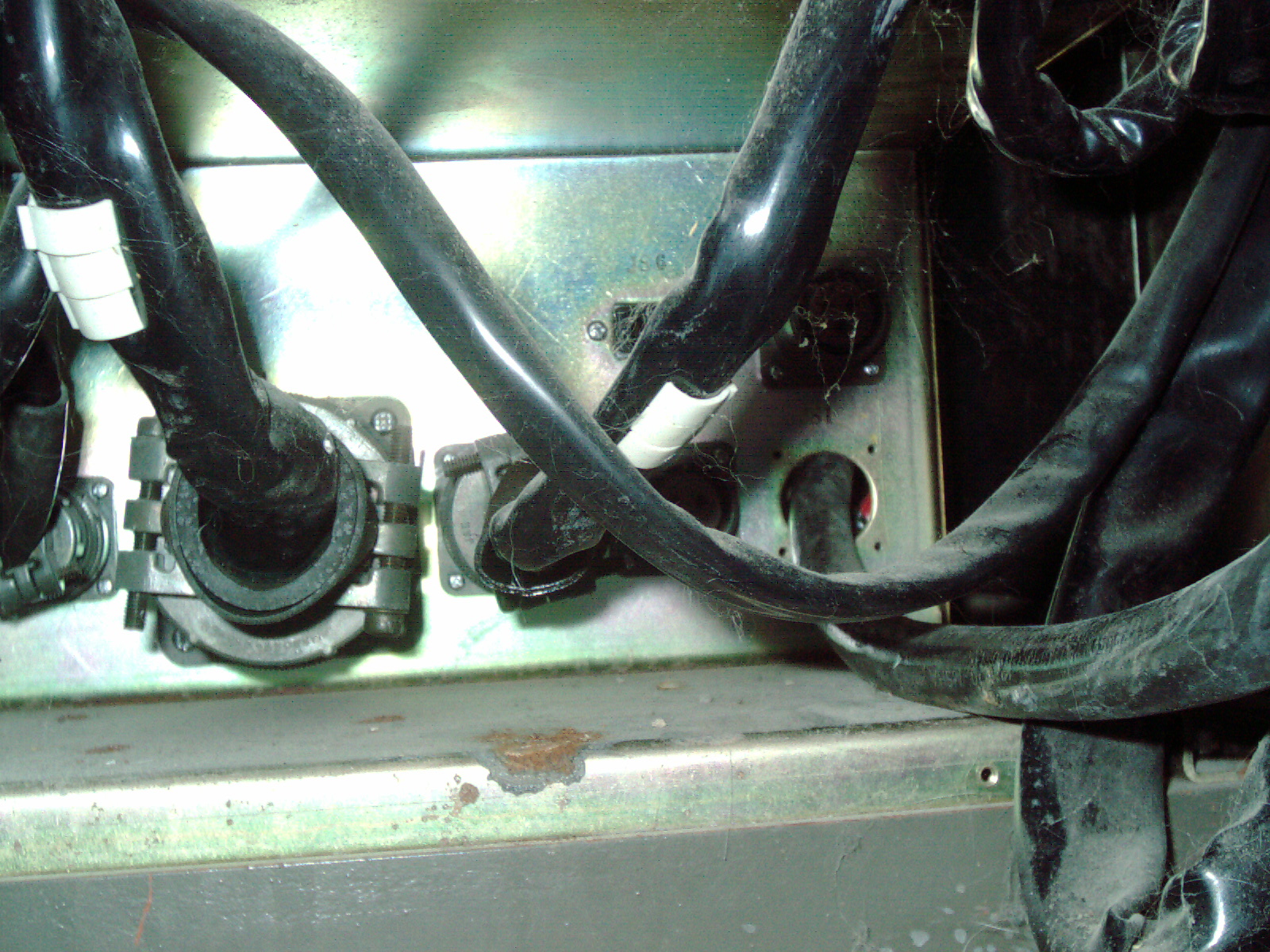
I moved my SX-30 a couple of feet from the wall (lots of dust and junk - cat sleeps on it) to look at the 100V AC power port and vacuum pump port. I followed the ac cord/plug end - and it led to a very low spot on the backside of the SEM. The JS1 location should have a 3-pin port but instead the previous owner jerry-rigged it to be a direct connection. I looked though my small inventory of stuff from the SEM previous owner and found a 3-pin miltary connector - Im glad they saved it. So in the above pictures - Im showing the JS1 port which I believe the previous owner removed and hardwired directly to AC cord.
I hope they didnt connect my 100V SEM to 125VAC otherwise something may have blown out.
Im currently communicating with a seller to buy some SX-30 parts which are missing from my machine. Hopefully we can agree on a price that I can afford. Its unfortunate that when a person is interested in parts all-of-a-sudden things become valuable. Whereas if no-one was interested - it would get thrown out.
Update 1/13/17
Unfortunately the California seller renigged on his agreement to sell me the transformer or any other parts. It is unfortunate as I needed these parts. Im glad to have acquired 1ea caster wheel as I can now move the machine a foot or 2 to access the backside. Also I have acquired some photos and screws. The seller had some cables and connectors which I needed also. Its too bad. I have posted some "thinking process errors" in which the seller connected the terminals wrong and wasnt able to get to 100VAC output due to this error. See further up the page as I posted these photos and article in TXT and zip files. Most importantly I suspect this error happened to me as a buyer TWICE (I now realize the "common thinking process error" with regards to ISI transformer)
Update 1/24/17
I mailed a payment of a one time use Visa Gift Card (a hand-me-down gift) plus $20 for the purchase of 1ea ISI SX-30 transformer with 2 cords (cut but mendable) 1ea caster, some screws. The California seller who renigged in my last paragraph was open to communicate and so made an agreement by email to sell these parts. Im sure there arent too many people who are looking for this set of parts. It would otherwise be disposed of. To me this is wonderful to find the parts that my machine is missing. Hopefully - no more renigging or other issues. Im not rich and the payment was difficult to make and comes in the very heart of Winter 2016/2017 when the coldest of the weather is about to begin and bills are easy to get behind on.
I received a box of SX-30 items in a USPO Flat Rate box. This is box 1 of 2 from California seller.
A summary of contents
1. power cords for transformer
2. box of filaments 99%
3. detector cord and mesh screen assembly (I dont know the proper name)
4. white Gloves 2 sets
5. Rubber o-ring 2ea
6. ziplock bags w/ screws 2ea bags
7. Yellow folder envelope with about 1" thick centerfold schematic pages
8. SX-30 metal label for the transformer.
9. Caster wheel 1ea
Im so glad the seller included some extra stuff inside the box. The next box will be the transformer and will be shipped this week. I see that todays box was badly beaten up and tears and looks like an accordian. I hope the transformer will survive the trip too.
The seller emailed this message 2/2/17
"The gloves are for handling the inner column components such as electron gun, anode, column liner assembly end the interior walls of the column. Never touch any of these things or anything exposed to high vacuum with your bare hands. The skin oils and dirt will degrade the vacuum, may cause charging which interferes with the electron beam and impacts image quality. "
Update 2/10/17
The 73lb UPS box arrived today. I lugged it just a few feet to my dolly and then to the SEM room. This tired me out drastically for some reason (lots of errands today) - so I didnt unbox it yet. It is a pretty small box for this amount of weight. I hope it survived without crushing etc.
Update 2/15/17
I emailed the seller asking for the next order in about 30 days approx. He quoted a price including Hitachi Vacuum Pump and cut cords, Oil Diffusion Pump, Heating Element for Oil Diffusion Pump, Camera assembly. I am trying to come up with the money to buy this lot.
Update 9/12/17
Since my last update, I had just recovered from winter bills and immediately was hit with another big financial obstacle - replacing the shingles on half of my roof. I performed the work in June (3/4 of it myself) and it left me tired from performing the work and financially drained of all of my savings plus outstanding debt. As I write this I still have about 2 months to go to be fully paid off. As winter is soon approaching (soon winter utility/heating bills) - that means that in 2017, I didnt/wont make as much progress on my ISI SX30 as Id hoped- but I did acquire alot of parts from one seller. I hope to acquire more parts from the same seller- but I cant right now.
Update 11/30/17
I spent yesterday unpacking some boxes and clearing space in my lab. One of these boxes was the 100V step down transformer and pleased that it arrived safely and was carefully boxed in a square fully enclosed plastic milk crate lined with styrofoam blocks and furthermore was in a double-thick cardboard box. I see scratches and cut cord and unscrewed top lid- but I see no shipping damage. Im happy it arrived safely - just like in the photos from seller.
I also am in the process of acquiring some other equipment which will reside in the same room- and made space for its delivery in a few days. By cleaning up alot of extraneous stuff - the room is much better and less cluttered. I sill dont have enough funds to buy more items from the same SEM parts seller - Im still not financially recovered from my re-roof project this year. Im glad I made some progress in aquiring some parts this year for the SEM.
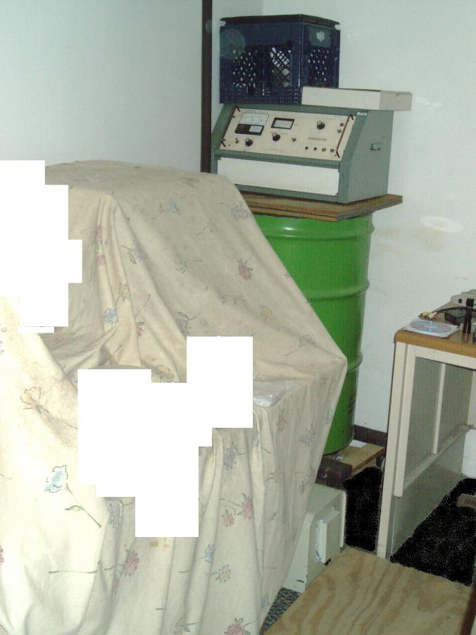
Over the last week I have made some cleanup/rearranging of my SEM Lab as I have received additional equipment and took effort to make space. I have moved the Sputter coater on top of the 55 gallon drum with a board as a platform. I have also finally unboxed the 100V stepdown transformer and put it on the right side of the SEM. I was planning on clearing the tabletop to accommodate the new equipment- a very large vintage 3d printer which will stay in this room either for awhile or permanently. I did some rearranging of the plywood which is a rolling surface for these heavy machines. As I had some time I fixed 2 machines due to the newly created space. Unfortunately I did not have time to work on the SEM. A thought occurred to me to make either a vinyl or bubblewrap cover for some of my equipment- this will keep it cleaner from the cats box dust which my cat frequently visits and is a sorce of dust which goes everywhere including inside of equipment. I think the SEM is pretty well protected with a sheet but would like to make a custom fit cover because dust creeps in everywhere. I spent alot of time with another piece of equipment I repaired cleaning out the dust from mutiple circuit boards. I hope the sheet will spare me that with the SEM in the future. I have blanked out parts of the above image - as it hides some clutter and mess.
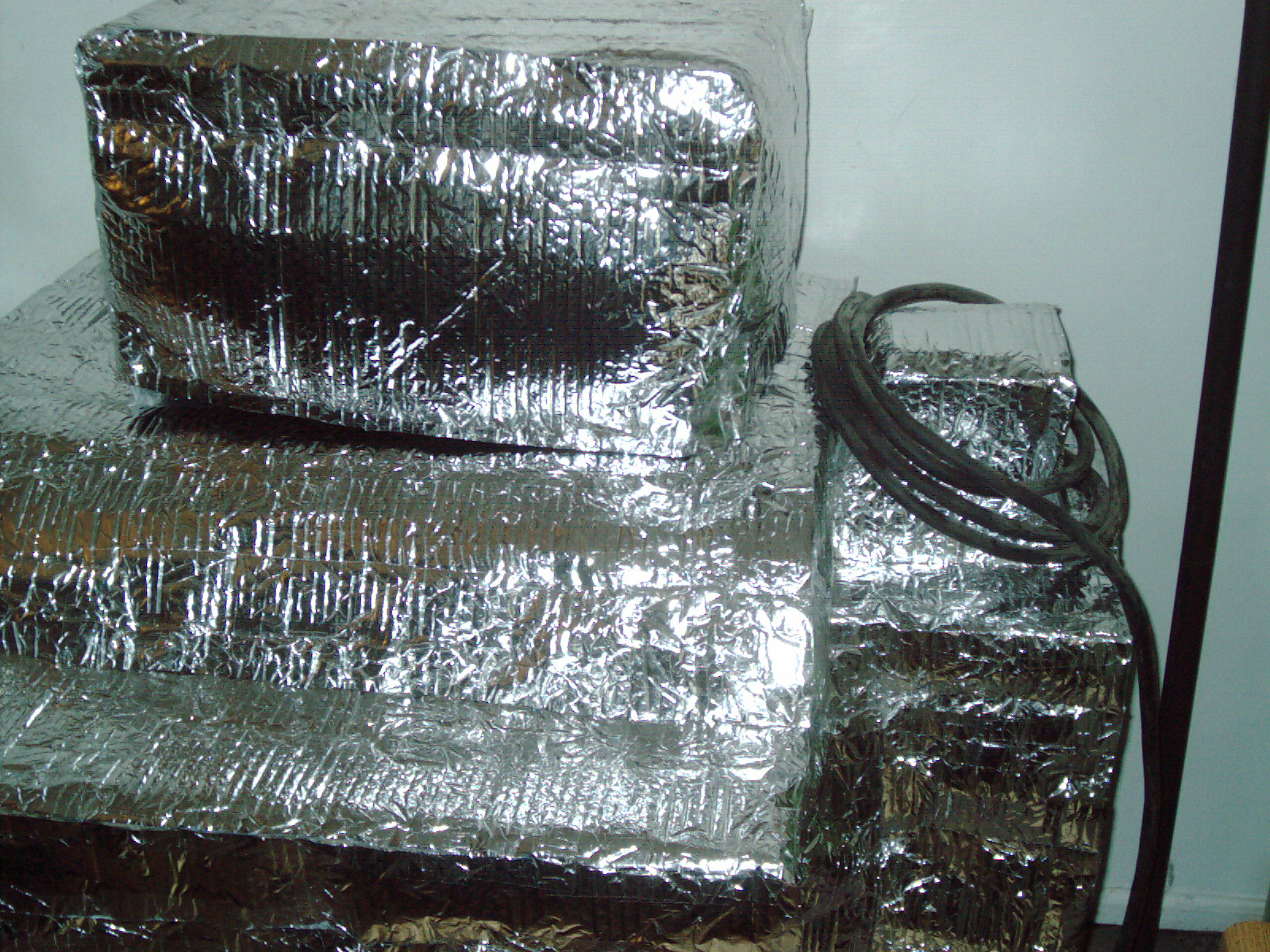
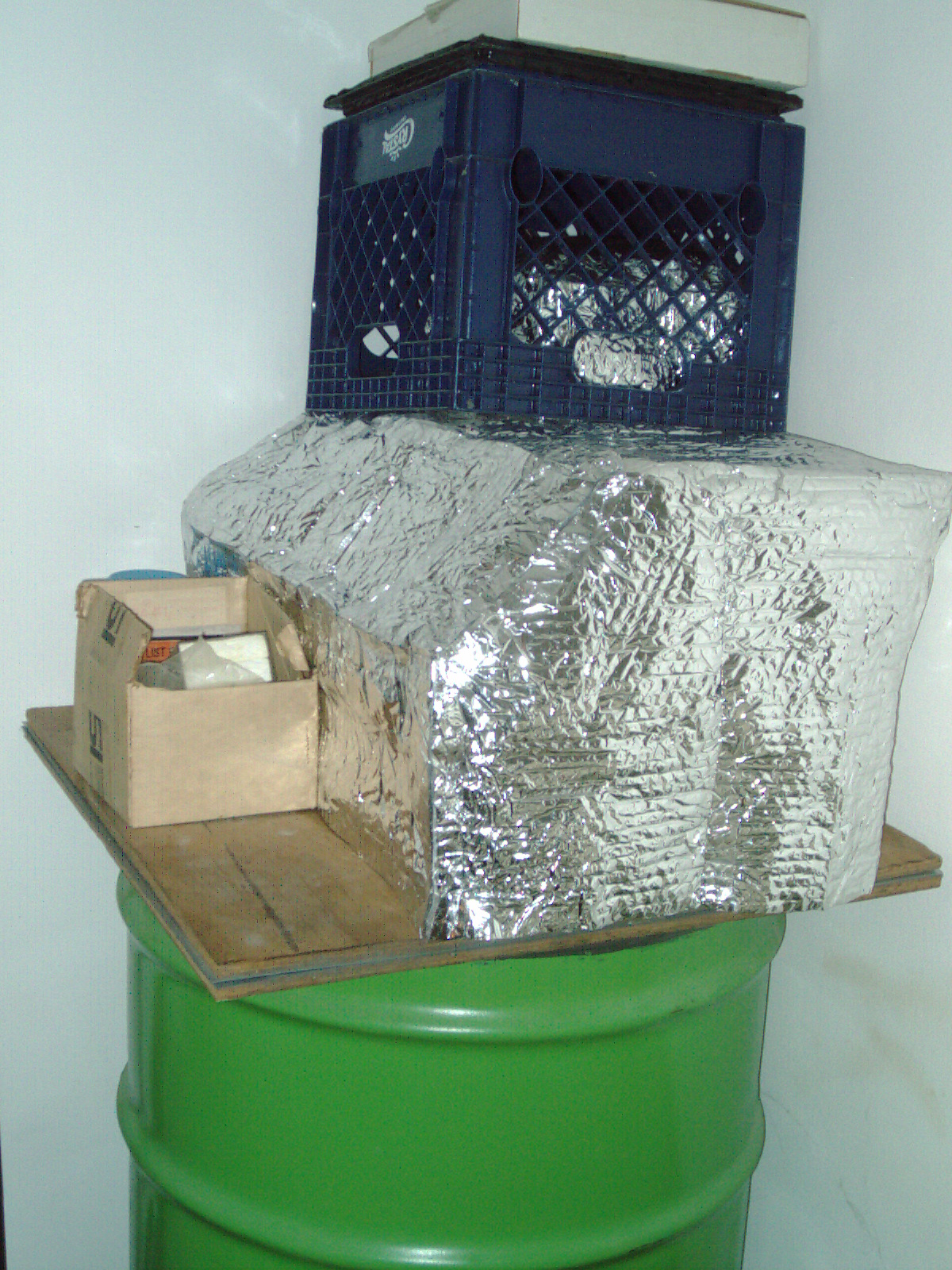
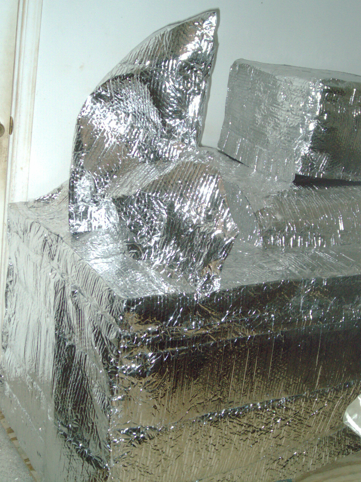
I spent 2 nights using shiny silver color bubblewrap packaging which comprises the material in my homemade dust covers.
I have accumulated from some machinery purchases over the years. This packing material is strips of bubblewrap about 3-5" wide and rolled up like a carpet. Then these rolled up "cinnamon rolls" are strategically placed around the machine during shipping. It is amazing how many of these are placed side-by-side and stacked to completely surround equipment. I had a whole box of these and I used 2 rolls of clear packing tape to make large sheets from these strips. After I had made these sheets-from-strips - I carefully cutout a pattern for each side/top/back/front of each machine - sometimes the machine had many facets or a diagonal area which I tried to mimic for a good or at least functional fit. Then I taped these cutouts together to make the actual Dust covers.
Here are a few photos showing my
1. Sputter Coater cover
2. ISI SX-30 Microscope cover
I think it is much better than the sheet which was on there before. My cats litter box and the vigorous scratching by my cats- throws up dust which gets everywhere. I just feel like this is the next step in getting these machines restored - dust covers will protect the machines from un-necessary cleanups/cat accidents/dust etc. Plus it looks alot better than a sheet. That room looks very space-age NASA looking now - with all of the shiny silver-reflective bubblewrap. I dont think it makes it EMP proof. Just makes it cat-litter-box-dust somewhat proof. The cost was 2 rolls of tape which I buy in bulk - so about $2 per packaging tape roll and well worth the money to get that room under control from dust and accumulation of dirt/debris from my cat which climbs everywhere.
I have contacted the private seller of leftover ISI SX-30 parts (same as I purchased from early last year) as I have received as a holiday gift from a family member $xx and am sending this as a downpayment towards the remaining lot of parts. The change in what was emailed last year is that the oil diffusion pump is no longer going to be included. That is too bad for me as my machine has a tinkered-with oil diffusion pump with amateur soldering/brazing??? regardless of whether he changes his lot for sale and price - I still need the parts he has for sale. He wants to include 1) 1ea camera assembly 2) 1ea Hitachi vacuum pump 3) 1ea heater element only from the oil diffusion pump (will be removed from the oil diffusion pump and sent separately) Even so I still need those items. I will shortly mail my downpayment. It took me a whole year to come up with the funds - and I still didnt have any extra funds- just breaking even. If I didnt receive this gift from a family member - it would be even longer saving up. Bad economy and my last years roofing project and middle of winter severely affects my savings.
2/6/18
I have found out that my local source for welding gas refills no longer carries anything but propane. I still have my 2ea welding bottles one for steel and one for aluminum welding. I was planning on using argon for my sputter coating. This local welding supply change affects my ease in obtaining inert gas. In the last month I welded a newly purchased folding metal chair leg (brand new item required welding because it broke LOL) and I more sparingly used the Argon/Co2 mix because I may not be able to replace it as easily as the last cheap fillup for $36 for an 80lb tank. I may be able to use the same Argon/Co2 for sputtering? I dont know. I forgot what the Aluminum welding half-size bottle uses- but I have that too and was more expensive than the other one to refill (my last refill was 5+ years ago). I saw a youtube video where people are homemade refilling their proprietary soda spritzer bottles with dry ice available at some supermarkets (I have no idea where to buy dry ice locally) and when the CO2 from the dry ice is sealed within the spritzer bottle- it becomes a liquid at room temperatures. This is not what I plan on doing and as I look at my above paragraphs - I always find a way to do things as professional as possible and the rinky-dink way was thought about - but ultimately I chose not to do it that way.
Also I found a source for a used badly covered in gold borosilicate tube, used gasket, used pealing target and used pealing center donut-hole target for my Anatech Hummer IV. But alas I have no funds to buy it. Even so the parts are in cringeworthy condition and the price is alot for me. If I had the money I would buy. I asked the seller to save these items and not throw out. I still have to pay a prior seller a balance. Its never ending and hopefully those deals wont vanish as it takes a long time to save. Here is some photos of those cringeworthy parts which I cant afford to buy now. In the sellers ad - he shows a whole bunch of brand new parts and pieces including duplicates. I asked how much for the old parts for all of the old parts which are in too bad condition anyways. Even those old parts have a hefty price. Right now it is winter and my furnace is guzzling away my funds. These images are good examples of what these parts look like. Also the image shows the sellers Hummer IV which at first glance looks just like mine - but no - see it has a solid sheetmetal top whereas mine has a mesh top. So even with the same brand and model unit - there are substantial differences.
Update 5/19/18
I contacted the seller of these used parts and he replied that the parts were sold months ago. It took me 4 months to save enough for these parts and it is unfortunate I missed out.
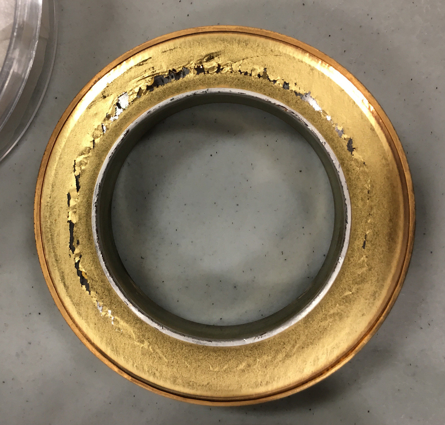
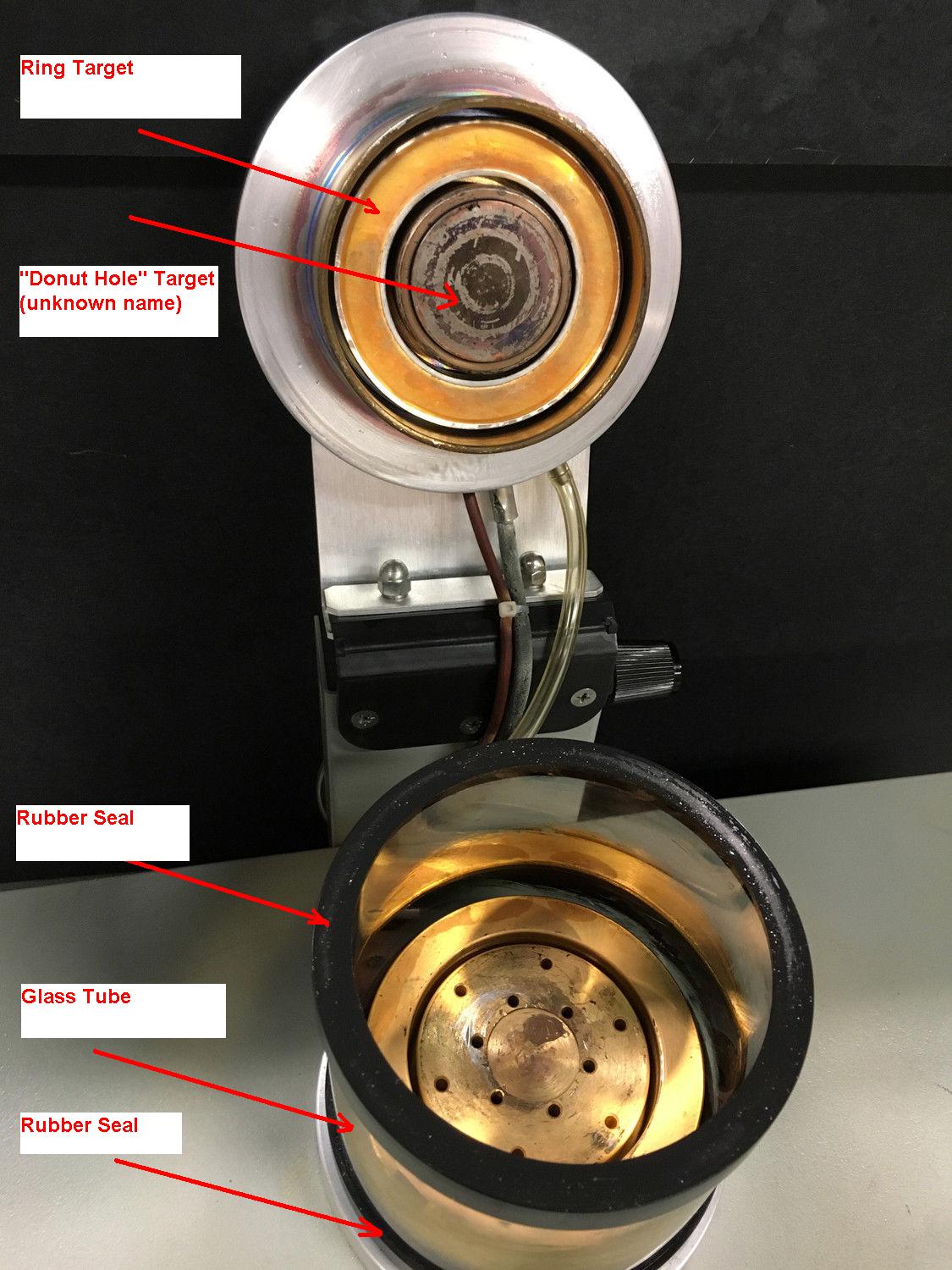
I just happen to watch some random repair video on youtube and had an AHA moment where I got an idea from watching this video about a man gluing 2 pieces of metal together with Shoe Goo repair.
https://www.youtube.com/watch?v=MjEW_euJeHU
I never used that product before. I wonder if it could work for my rubber accordian-like covers which surround the springs. I might try that in the future. I also have a pair if vintage rubber snowmobile boots which have a crack - so it would serve 2 purposes. Im first concentrating on coming up with funds to buy more parts from the SEM seller. Winter bills are tough right now.
Update 4/29/18
I have paid the balance on the lot of ISI SX-30 parts which is for 1ea camera, 1ea Hitachi CuteVac pump, 1ea oil diffusion pump. I look forward to receiving these items. I asked the seller to put the oil in a separate container. This seller has done a great job shipping SX30 parts in the past, and Im hoping for the best this time too.
Update 5/14/18
Update 5/19/18
High Shipping Cost for 2ea UPS Boxes (approx $100 wasted)
I have paid a little over a week ago $79 for shipping cost for the first box and today $111 shipping cost for the second box (on its way) for the 2nd box which contains the Hitachi Cutevac vacuum pump. They were shipped by UPS and Im scratching my head on why the shipping cost was so high. I dont have a UPS near me (the closest on is 40miles away) and the only UPS shippers are UPS stores which have a high markup and I never use them to ship. I remember once attempting to ship a few ounce 6" x 8" padded envelope with craft foam "dots" and the UPS store tried to charge me $18 and I cancelled that and took it to the Post Office for less than $5 shipping. Last year I purchased an old 60lb Reel to Reel VTR and seller shipped by Fedex charges were approx $55- this is approximately the same weight as the Hitachi vacuum pump and goes to show how inflated this UPS shipping cost is on this order- double what I expected it to be. That means about $100 of my savings was wasted/depleted for no reason. I was hoping to have enough to buy the glass for the sputter coater- but I cant do that now.
I dont know why the shipping cost was so high on these items- I have once again depleted my budget- and the actual shipping by Fed Ex ground would probably have been substantially less - that is my hunch. I didnt argue/I-didnt-mention-it with the seller, Im glad he shipped the items and included extra items such as the tube liner, hose, oil filter, etc that would have been difficult to locate replacements for. Also, filaments and gloves and other items were included in previous shipments. I could not have found a better seller and exactly offset almost everything I was missing. However high shipping costs meant my dollar wasnt stretched as far as possible- and means I may lose out on obtaining the sputtering coater parts.
I will look for the vacuum pump to arrive this week.
5/25/19
I received the box yesterday which contains the pump. The box is extremely heavy and packed in a very small box. I havent opened it as Im swamped with work to do right now. Opening it up will only make me put it to the side where some part of the pump might get misplaced. Its better for me just to leave it in the unopened box for now.
I received 3 emailers telling me about another college/university with an online auction for an SEM microscope. It makes me scratch my head on why people write to me to SELL or REFER a microscope instead of buying it themselves?
SEM microscopes represent the upper 10% of the pinnacle of technology and upper thinking process minds in the world. Our worlds population is increasing dramatically with every generation. Our upper technology is being thrown in the dumpster and Universities are "unwittingly" putting us closer and closer to the darkage/stoneage everytime they dump one of these rare machines. The ratio of people to SEM microscopes is getting higher and higher.
I can only save one SEM and I made my choice to save this unit. As of right now I have spent thousands of dollars and 4 years in acquiring parts/pieces/shipping etc cost for a microscope I have never plugged in.
Owning a SEM is a very very rare thing and every time a vintage SEM is destroyed they become more and more rare.
Im saddened by SEM microscopes being destroyed and by emailers/callers not taking up the challenge themselves to save one. Looking at microscopic things whether it is organic or inorganic is one of the tools of progress. And the world has not progessed much in my lifetime - and in some ways gotten worse including more extinctions of species.
My obstacle is day-to-day bills, mortgage and keeping food on the table and etc. The money system and daily life makes my SEM project take a very long time. I have the longest attention span- and will stick with this project until it is done and kep the machine for my lifetime as a tool. One of many tools I own which enable me to do and achieve things and make and invent things.
Update 8/26/18
I was emailed some photos of a steel side panel for sale for SX30. I have emailed the seller (same seller as before) that yes I do want to buy the panel- but Im low on funds now and the purchase will have to wait. I am missing some steel panels for my machine.
Here are some pictures of the sellers panel.
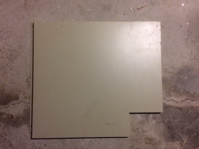
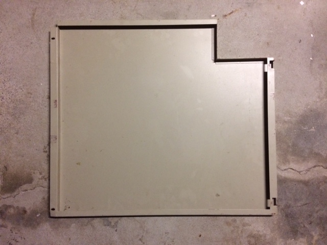
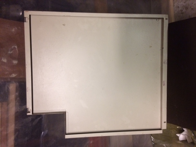
I keep getting emails from people who gloss over important. Just like the HORRIBLE manual glosses over information. A manual and instructions should be EXTREMELY detailed. Remember the VIC20 or 64 manuals? Remember the ATARI 800 and APPLE IIe manuals that taught millions to program? The silly cartoon characters on the page and big cartoon <ENTER> <Return> step-by-step reminds people on keys and syntax error ... etc
The ridiculous press this key and turn this knob pages- taught millions - otherwise computers would not have caught on - like they did.
And comparing this detailedness to the ISI manual is THUMBS DOWN no comparison. Reading emails from people writing to me offering advice and questions about their own problems. Those people CANT UNDERSTAND the perspective of a person who has never seen one operated (me).
The information provided by emailers is baby-stuff when I need Encyclopedia level detailedness and knob-turn/button press sequences/switch selection.
Here is an email from a person who is both asking for help and trying to provide help to me for how to startup. I asked for a video and the LAZY $&^%&%#%$ is providing a one paragraph summary-like answer DOY!!!!!!!!
I learned nothing from this "babystuff" type emailer ... and my email reply only restates what is contained elsewhere in this webpage for his issues.
|
|
baby stuff emailer name blanked 090818.txt Size : 2.866 Kb Type : txt |
Update 10/22/18
I was emailed some photos of someone else's SX30 which they are in process of repairing. Here are 3ea zip files showing partially disassembled. Most notable is the common everyday socketed chips that populate the boards. Very testable using cheap IC tester from big-auction-site. A very repairable and accessible machine. I gave that advice to the emailer/caller who originally wanted a schematic from me and I explained that unplugging each IC and testing it one-at-a-time is the best approach to troubleshooting this machine.
|
|
ISI SX 30 Emailer 102218 Part A.zip Size : 10649.519 Kb Type : zip |
|
|
ISI SX 30 Emailer 102218 Part B.zip Size : 12061.233 Kb Type : zip |
|
|
ISI SX 30 Emailer 102218 Part C.zip Size : 13814.998 Kb Type : zip |
Update1/8/19
I was contacted by the same seller about 3 items he has for sale and he offered me a lot price for all three things
1. 1ea Steel panel (see pic above)
2. 1ea Box of filaments (not pictured but he sais brand new/sealed)
3. 1ea ISI Robinson Detector and cable (see this pic gallery)
I expained that I just dont have funds to purchase right now as it is winter etc. I just barely have enough to make my mortgage payment.
I am posting pics of the ISI backscatter detector here in this gallery:
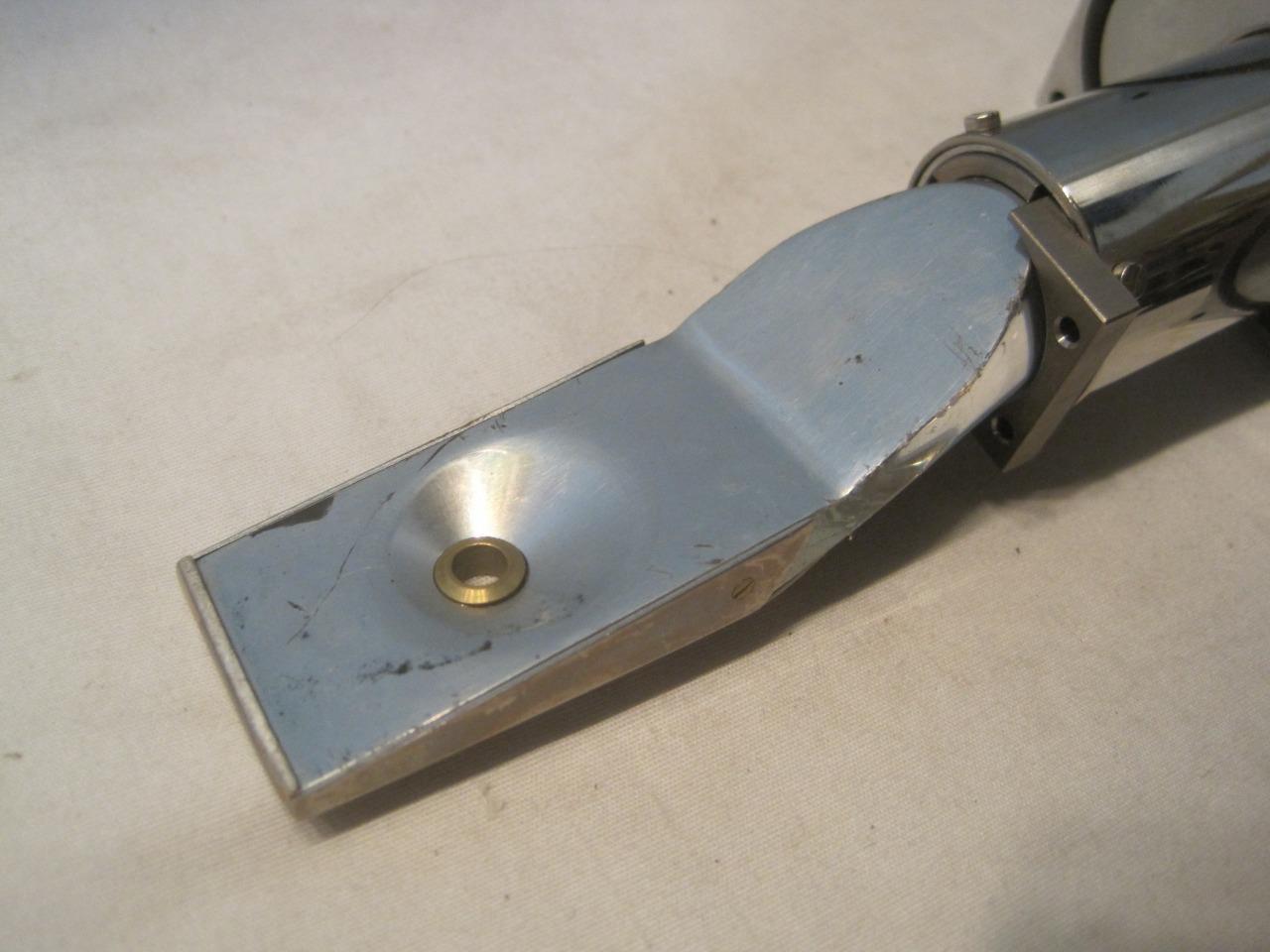
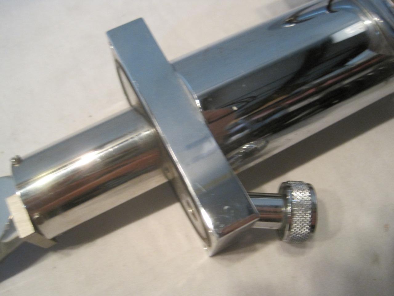
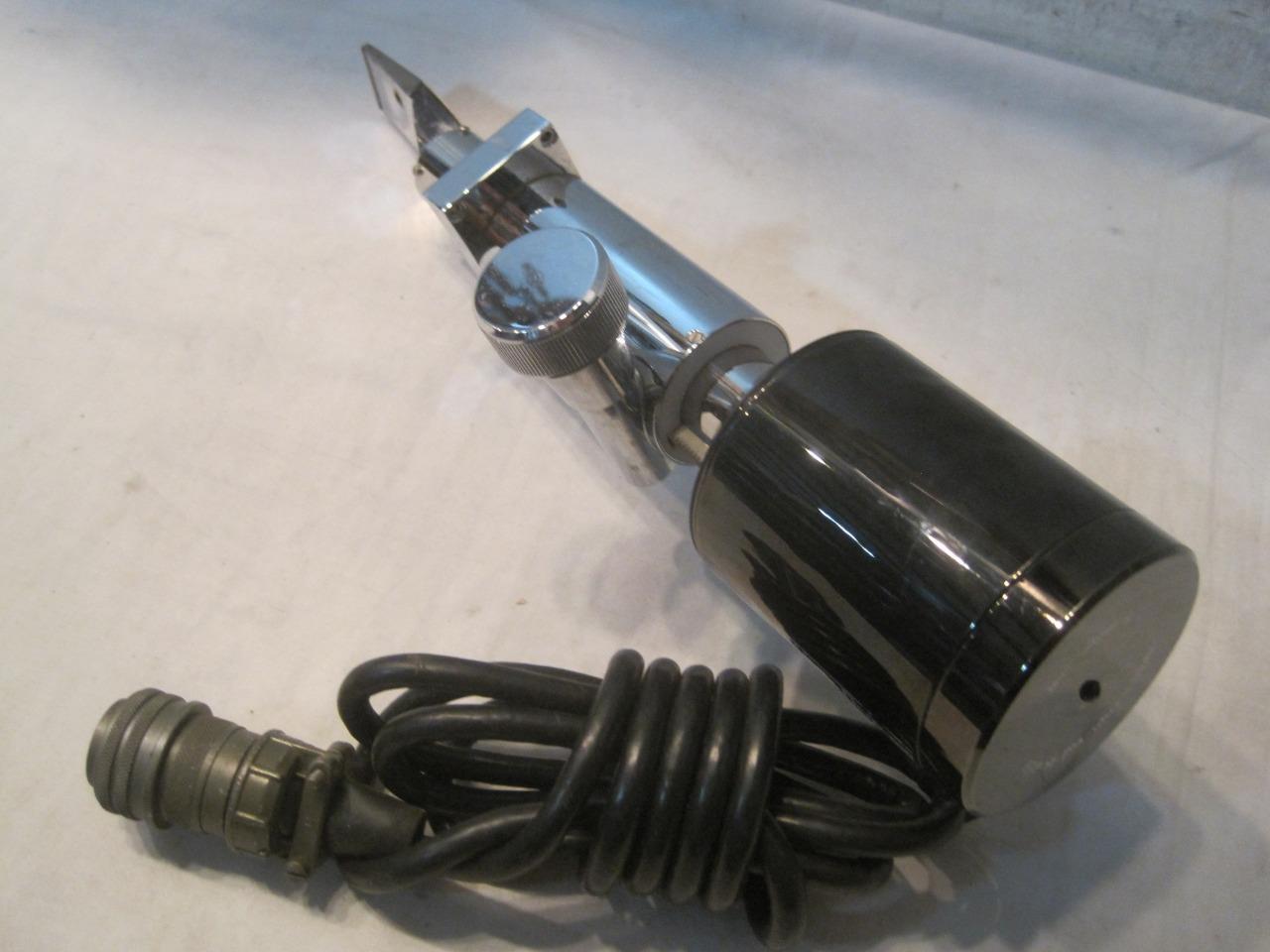
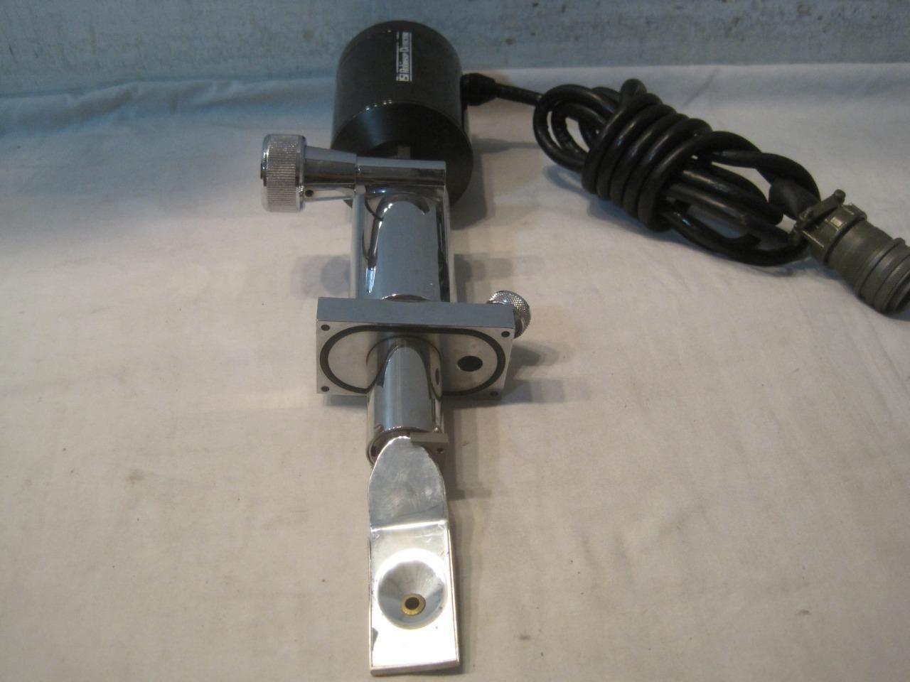
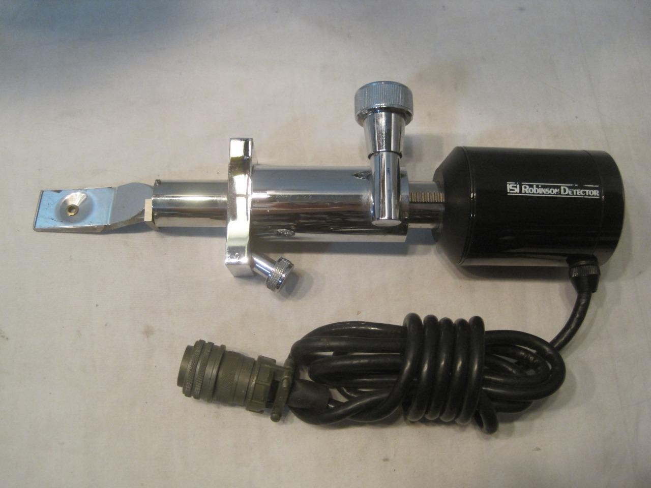
I have 30+ years electronics & restoration & engineering etc experience and many ic testers and parts checkers etc I believe that I have the skills necessary to restore this machine. It will take time, money, and patience. Sometimes I will need to improvise as not all parts may be available.
Let me know.
Dr Virago Pete
(847) 454-7858 between 11am and 7pm daily
My email address:
drviragopete@att.net
Some similar models which may have exactly the same parts I need
ISI
SX40, SS40, SX30E, SX30, SX25, SX60, SS60, model 40, model 25, model 30,
model 60, SMS 3A, SMS 2 (SMS2 column looks possibly identical to mine) and others??? Sometimes ISI microscopes are referred to as "
Topcon " I realize all these microscopes have differences but they also
may have some parts in common- please check your
parts-machine/donor/non-working SEM to see it if has the parts I need.