Here is a paypal button for $10 Quote Consultation Fee. This covers my time in phone or email communication. Speaking writing and download/upload photos takes time. I charge for my time and services. This $10 does not apply to any parts or services and is non-refundable. I find that this tends to screen out 99% of emailers/callers. The 1% of emailers/callers are my buyers. I reserve customer service and technical answers to buyers only. I reserve the right to say no thankyou or to charge more due to the complexity of the question etc. I perform repairs and or diagnostics service for -circuit boards/parts etc. BUT no repairs and no diagnostics testing services are included in this $10 Quote Consultation fee.
Dr Virago Pete's Electronic Parts Testing Service
Send your desoldered components ready for test
1. Desoldered
2. Wrapped carefully
3. Return envelope and postage affixed
Solid state & Semiconductor Components I can Test
1. Transistor
a. NPN & PNP
b. Mosfet
c. IGBT
d. Power
e. others
2. Diode
a. Germanium
b. Silicon
c. Zener
3. Capacitor
a. Capacitance
b. ESR
4. Inductor
5. IC Chip
a. TTL Logic Chips
b. 7400 series chips
c. 5400 series chips
d. 4000 series chips / CD4000 series chips
e. HEF400 series chips
f. 4500 series chips
g. ULN series chips
h. others
6. Voltage Regulator
a. 7800 series
c. 7900 series
7. Varistor
8. Optocoupler
9. Solenoid
10. Surface mount components / SMD.
11 Analog Chips
This ad is aimed at the DIY student or hobbyist who is working on his/her own electronic device and needs assistance in troubleshooting.
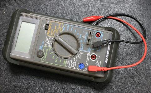
Consumer-level meters simply do not have the ability to thoroughly test solid state electronics. For example the average multimeter can only test Volts and Ohms.
Intermediate level meters can check capacitance but not ESR. These intermediate level meters can test transistor gain but not leakage. This leads to frustration in the student or DIY repairman/woman because they are looking for a fault they cannot find.
I have professional test equipment which can thoroughly test components you send me for test. Most components on a PCB are soldered in place. You must carefully desolder components before sending them for test.
Identification of Unmarked components
1. Scratched off markings
2. Worn ratings number
3. IC chips
I am looking for a "U-TEST-M" vacuum tube tester made by Colonial Merchandising model 2500 and when I purchase one - I will update this ad to include vacuum tube testing service also.
I am looking for a "Linear IC Tester" or "Universal IC Tester" and when I purchase one or more I will add this to my list of chips.
There are many parts I have in stock as replacements and some that I do not have in stock. I also have many books which show the ratings of thousands of parts. I can also cross reference substitutes and replacement parts.
I can identify a replacement/substitute for most parts.
What Makes Dr Virago Pete Qualified?
1. I own many parts checkers and testers
2. 30+ years experience in troubleshooting electronics
3. Former Electronics Instructor
Tips
1. Always put your IC chips in sockets when building a kit
2. If your device runs on batteries - dont run off power adapter
3. Use a correct soldering iron 15watts or less
4. Learn to desolder quickly without overheating your parts.
5. Take a detailed photograph of your PCB and make notes and sketches before desoldering anything from the board.
6. Don't tinker - do it the right way - or don't do it at all
Contact me if you
need chips or other electronic components tested. I try to be reasonably
priced. Many electronic devices made in the 1970s, 1980s, 1990s, 2000s,
2010s used off-the-shelf stock chips for all or a portion of their
functions. I can test these industry-standard parts.
What I'm trying to say is - when you are repairing a device - finding the 1 bad component - whether it is an IC chip or other - you hope that it will be a common part that failed - one that you can easily replace and is readily available. Most likely your device has failed in one or more common parts - cheap to replace - but the trouble is - in identifying which one has failed.
The number one cause of failures in electronic devices is electrolytic capacitors (sometimes obvious due to the bulge) and sometimes tantalum capacitors will spontaneously cease to function or pop/explode - as these can fail quickly - sometimes while letting out a very foul smell unique to a dying tantalum capacitor (several aerospace companies refuse to use tantalum caps in their space missions)
I can test
capacitors with my professional ESR tester. Bad capacitors do not always
bulge. Sometimes electrolytic capacitors will make a loud POP like a firecracker as it is dead - bulging the top or not bulging the top. Most failures are not dramatic and make no noise or smoke or smell. Equipment is necessary to identify these bad components without visible clues - which is where my expertise comes in.
Dr Virago Pete
(847) 454-7858 between 11am and 7pm daily
email address drviragopete@att.net
Located in Illinois USA
My assistance is not free - reasonable fee - call to inquire.
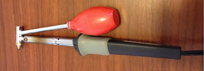
I use quite a few desoldering methods and decided to add some insights about my Soldering / desoldering equipment. I normally use a Radioo Shack desoldering iron with red bulb for my everyday desoldering of parts, but occasionally I will have a particularly stubborn or delicate part and I am always looking for alternative ways of desoldering parts.
I have the following Soldering / Desoldering equipment
1. Radio Shack 15/30 watt switchable soldering iron (the one I use the most) 120V I have went through a few tip as they tend to get eaten away by solder and flux. I also use a fine metal file to clean it up when the tip gets nasty. I like when the tip gets short as it heats better. When the tip is new and long it doesnt heat as well as when it is short. I dont often sharpen the tip - only when I have a very delicate soldering job like high-pin-count ICs. The tips unscrew so it is possible to change between semi worn tips and brand new ones. I usually keep a spare tip in my soldering tool box. Previous to this I used a gun handle style soldering iron from Radio Shack approx 30 watts which I liked also but burned out after 10 years of use - not a bad reflection of the mfg at all.
2. Radio Shack 45 watt desoldering iron with red rubber bulb (the one I use the most) this is my second unit as the first one burned out after 15years of regular use which was very reliable and hardworking. 120V I have went through a few tip as they tend to get eaten away by the solder and flux over a long period of years. I usually keep an extra tip in my soldering tool box.
3. Radio Shack Portasol Butane soldering iron - purchased used (tip burned out after 10 years of regular use - I bought an aftermarket brand new in the package Boardworks tip for it (with slots rather than original keyhole shape - and the slotted tip burned out after 1 week of light occasional use) I still have not ordered a replacement original tip as I dont want to keep throwing money at this tip replacement issue - which the tips are expensive. Was very useful for soldering PCB with very large amounts of solder or where high heat is needed - like to reattach coaxial connector on RF shield - where a normal soldering iron just doesnt have the muscle to heat. I like this unit and the burned out tip isnt a bad reflection on the mfg as I got 10 hardworking occasional use years out of that standard tip that it came with. 60watts approx heat output with standard tip. I replaced the flint with a standard Robinson lighter flint as it was worn out from my use and the previous owners use. Update 10/4/16 I have purchased a set of 4ea tips for Portasol and to my amazement - the brand new soldering tip didnt work good after 3-4 soldering sessions - making sooty big flame when lit, sputtering, not glowing red hot, flakey and difficult to get it to work - WELL here is why and how I fixed this issue. See Butane turns into water as a chemical reaction. Over time (my Portasol is over 10years old and used very often - NICE TOOL) there are water droplets/trapped air etc inside the unit. I fixed my unit to much improved but still not perfect condition by using a 1/8" metal rod (Dremel tool end shaft) to push up on the butane fill valve. FFFFFFSSSSSSSFFFFSSSS the butane sprays out the bottom (wear rubber gloves) and this pushed out the water and air. The next time I used the Portasol - it worked and lit much better. I may have to repeat this step to fully get out the contaminants. Dont get me wrong I really like this soldering iron. Its not the fault of the unit or the butane from the hardware store. Butane itself turns into water and collects inside over time - just like a pair of glasses gets condensation coming into the warm from the outside cold winter air. Butane is a gas and gets compressed- when sprays out - it is very cold- thats where the water comes from combustion and also the cold/hot/cold/hot ... condensation.
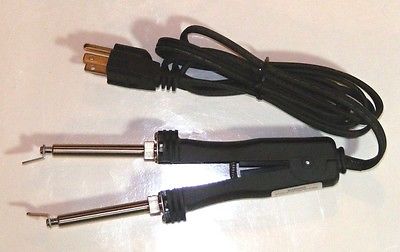
4. Tenma desoldering tweezers 21-8230 purchased from big-auction site) and I made a few custom-made tips to remove ICs with it. 45watts 120V I like the dual soldering iron design and see my other page for the tips that I custom made for my unit.
http://www.drviragopete.com/ic-desoldering.php
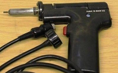
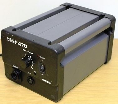
5. Hakko 470 desoldering station with 803 gun (I bought used and doesnt work quite right- temp adjustment even on highest setting doesnt melt some high temp solder but still work fine for normal good type solder but heating could be better - possibly needs adjustment or a weak/worn electronic component inside) This is not a bad reflection of the mfg as it is 20+ years old and Im not the original owner - I have a spare gun and purchased some oddball things it was missing from big-auction-site like solder reservoir spring, and ceramic filters. These little parts are very expensive and I was glad to buy this used unit for a low price on auction- but the little missing/replacement parts pieces add up very quickly in cost. Most electronics enthusiests are nortoriously little-or-no-cost $ spenders. 120V adjustable heat
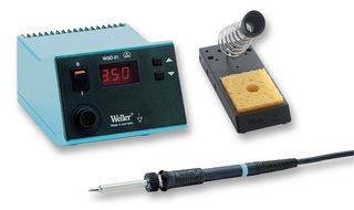
6. Weller blue adjustable temp Soldering Station WSD80 - in disrepair/disassembled - purchased it that way from an online auction. A restoration project I hope to find time for. It looks like a good unit and the disrepair is not a bad reflection of the Mfg. It is over 15 years old and who knows how much the previous owner used it? My hunch is it is approx 80watts max of heat with the iron I have and is temperature adjustable. I dont know what is wrong with it at this time as it is disassembled and never been plugged in by me.
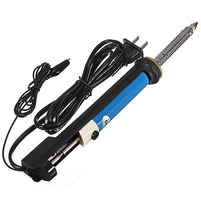
7. China Imported Blue/White desoldering iron solder sucker 220v 30Watt - never used as it runs on 220v not 110V
Update 5/5/16
I recently purchased a very inexpensive desoldering iron with built-in solder sucker pump (see picture blue/white unit above) and decided to purchase from a California big-auction-site seller. I received the unit in about a week and was just like some of the youtube videos which shows the product. I decided to disassemble the electrical cover just behind the push down lever and I see 2ea bare wires (just like the video) and I also measured the ground aligator clip end and I see no continuity between the hot tip and ac prongs or ground wire - I checked every combination. So the alligator clip ground is non-fuctional. I also spent time researching this item in forums and on youtube videos and there seems to be some confusion on whether this advertised 220V 30W unit works on standard household 120V (as it does have a normal 120V plug) and so I plugged it into my household ac outlet (measures between 123V to 126V AC typically) and the unit does heat up but never sufficiently to melt solder- even after leaving it for an hour. So it gets hot enough to burn your hand but not enough for solder melting on 120V. I was also under the wrong impression by the ad that it runs on normal household ac - but I did see the 220V in the ad also. So to put aside the confusion, I am posting this short article about it. I am still glad to have it even though I have not actually melted any solder with it. It came with a cleaning rod and 2 total tips - one with a fine time and one with a bigger hole. I plan on buying a small travel power adapter which converts 120 to 220 AC to use with this unit. Alternatively, I could disassemble and add nichrome wire in the correct amount to make it standalone 120V but I think I will just buy a cheap small travel adapter as a better solution. Maybe in the future they will make one that runs off of 120V standalone.
You would think that a 220V 30Watt de-soldering iron running on 120V would be a 15watt - BUT NO - it is not like that at all. It simply does not heat sufficiently at 120V. This is not a fault of the mfg but rather a miswording of the advertisement. The only fault of the mfg is the ground alligator clip which is non-functional. Frankly - few soldering irons have a ground wire and are mostly 2-prong. So having a non-fuctional alligator clip leaves me to either snip it off or attach it properly or leave it as-it-is. I havent decided on that part. For now I put it back in its package and will just add it to my close full of electronic gear and parts and stuff- which I use on special occasion. I was planning on using this to fix a particularly stubborn power inverter where the through holes are barely big enough for mosfet legs to squeeze through and they used hard to melt junky solder. I was hoping to find a better desoldering method for these difficult oddball boards - but alas this desoldering pump iron combo wont work on my 120V ac outlet. So until I get a step-up transformer of some sort- I cant actually use it. I only paid a few dollars for it- so Im still glad to have it and someday I may wish I bought a spare - who knows I may find a use for it. No holder was included and it seems to be balanced where if I lay it on the table - the tip doesnt touch the table - but still I will use a small Radioshack bent-piece-of-sheetmetal style soldering iron holder which I already have.
I see that some USA sellers have a "Tenma" model which is Yellow and White - and is probably color coded - Yellow unit for 120V and Blue unit for 220V. So I probably just bought the wrong color. Read the ad because it is possible that the color of the unit does not always match the voltage.
I like to use the bent piece of sheetmetal style soldering iron holder as it has very little contact with the hot iron and so doesnt rob the heat from the iron. I also have a Weller holder and soldering iron which is not functional and I bought it disassembled (previous owner repair attempt?) from a big-auction-site - but have never attempted to repair it - not enough time in a day/funds to get to all projects unfortunately.
I dont leave my soldering irons & desoldering irons running idle - I unplug them when not in use and plug them in just as I need them - letting it warm up for 10-15 minutes before use. This prolongs the heating element life and saves on utility bills cost- that is my personal view and you may disagree - as some people feel leaving electronic equipment like computers on prolongs their life (I disagree) and that the power cycling on/off is what actually shortens the life of equipment. You can have a different view - no problem. I always unplug my electronics when not in use.
Update 5/19/16
After about 10 years of having purchased and not assembling a used Weller WD80 soldering statiion (purchased nonworking and disassembled) I decided to work on it today. I cleaned all the individual parts using a bottle of dilluted green cleaner and water and spray bottle which I used for that cleaning fluid. I noticed that the previous owner boogered up some parts like the digital temp buttons are mashed and solder dings and the case has been exposed to alot of flux over the years and is splotchy- but I cleaned it up and looks better than before but not perfect. The transformer is mounted to the case bottom and plastic had a crack so i switched the ground wires to a screw closer to the the front of the unit which allows the back screw to screw down further and grips the remaining plastic hole and holds the cracked case better. I bent the sheetmetal heatsink away from the board - to a 90degree angle. I used my Capanalyzer to check all the capacitors and I did find one SMD electrolytic which had an ESR of 10 and an adjacent identical which measured 3. But I left it alone. I also checked the diodes SMD style and found none that triggered the ESR meters alarm. I used my Fluke 73 multimeter in diode check mode to check all the diodes and found none shorted and I also checked the 2ea TO220 package devices (possibly transistors- I didnt need to check) for shorts between legs and found no shorts. At that point I reseated all of the clips to make sure good connections. I also removed the fuse from the AC rear plug jack. The fuse tested good removed. I reinserted after bending the fuse holder 2 pins straight as it was a little cockeyed. I used the Fluke meter's continuity check to systematically check the AC prong and input lines to make sure fuse and continuity from AC cord was valid. I powered the unit up disassembled - making sure nothing electrical touched while live. I found that the Weller WD80 does not power up while the soldering iron is not plugged in. When I powered off and connected the soldering iron - then repowered on - then the digital display lit and the soldering iron heated and maintained whatever temp I selected. I carefully bent the heatsink back to straight and reassembled. Later that day I used it to desolder some N-Channel surface mount FETs from a non-working motherboard and tried various heat settings from 500-700.
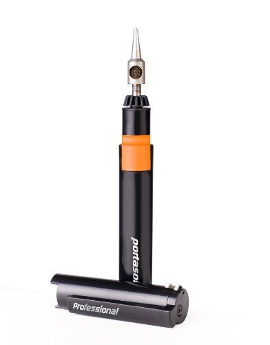
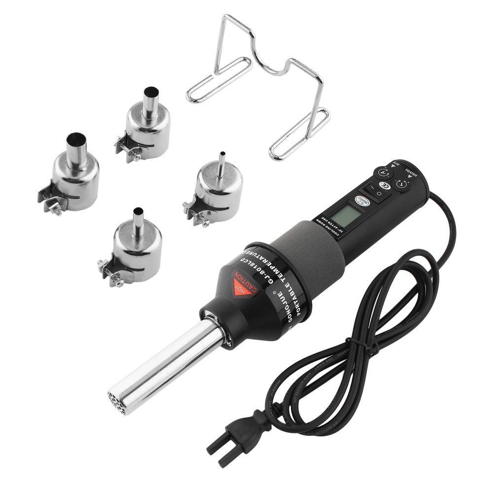
I have decided to purchase a handheld hot air tool today GJ-8018LCD purchased from China seller on Big-Auction-Site. It was a pretty good deal at $34.57 for the 110V 200watt version, and I look forward to receiving it. I have an upcoming project of replacing some surface mount components for a 3000watt Power inverter for someone and this is a good time to add this tool to my vast tool inventory. The miniature surface mount components were provided by the mfg and if it were just one or two- I could get by without this tool. But due to quite a few that need to be replaced- this time saving tool is necessary. Also, I am interested in plastic welding- and this looks like it could be suitable for plastic welding rod for repairs of big plastic items such as car bumper, garbage can, snowmobile hood, etc. I dont work on those type of things- but I have been thinking about disassembling some motorcycle batteries that have a bad cell- so being able to weld the case back together is on my mind. Also, I decided to replace my non-working Radio Shack Portasol (very trusty for many years but died awhile back) with a $30 Portasol P-1 I found brand new on Big-Auction-Site. These purchases are a splurge since the upcoming project covers these costs - and will come in handy to perform the repairs on the 3000w power inverter. The Portasol is especially good at heating large solder islands - which smaller soldering irons have a really hard time with. I like how my old Portasol made a nice neat job of smoothing out the large amounts of solder on these BIG areas of solder - very pretty end result.
I have had no-problems-that-come-to-mind about ordering directly from China. The parts and supplies and equipment are usually pretty good, decent and just what I expected. I see some youtube videos about repairs about this item. Hopefully, mine will last a good long time. After watching some videos about this GJ-8018LCD unit- there was one that mentioned the need to observe correct shutdown procedure- turn temperature dial to lowest setting and internal fan to highest setting - just before you turn off power switch. This is to evacuate all or most of the heat from inside. Otherwise the heat has nowhere to go when it is powered off abruptly.
Update 1/22/18
There is a decal on the unit which states - to let the unit cool down to 30 degrees C before you turn off. I suspect that if you shut off with inernals hot - that you would melt something inside - like the case and or fan etc and cause severe damage. I have experimented with my fixed unit and works fine now and I let it cool down to 26 deg C before I shut down- this caused no harm and the next time(s) for using it - worked fine.
It is my experience that SMD chips and SMD components usually dont go bad too often. I havent run into a big need for a hot air station or hot air tool. Usually in those equipment that I repair - it is some discreet/through hole component like transistor or mosfet or capacitor that has gone bad. But since someone is sending me their 3000W power inverter and a whole lot of parts they want replaced (the Mfg provided them all) then thats what have to do for that buyer.
Update 1/21/18
I have received my GJ8018LCD Hot Air desoldering/soldering tool and had some issues from the factory that needed repair. I think it is a worthwhile good tool. Unfortunately I got a bad one- unlucky for me - but I still recommend getting one.
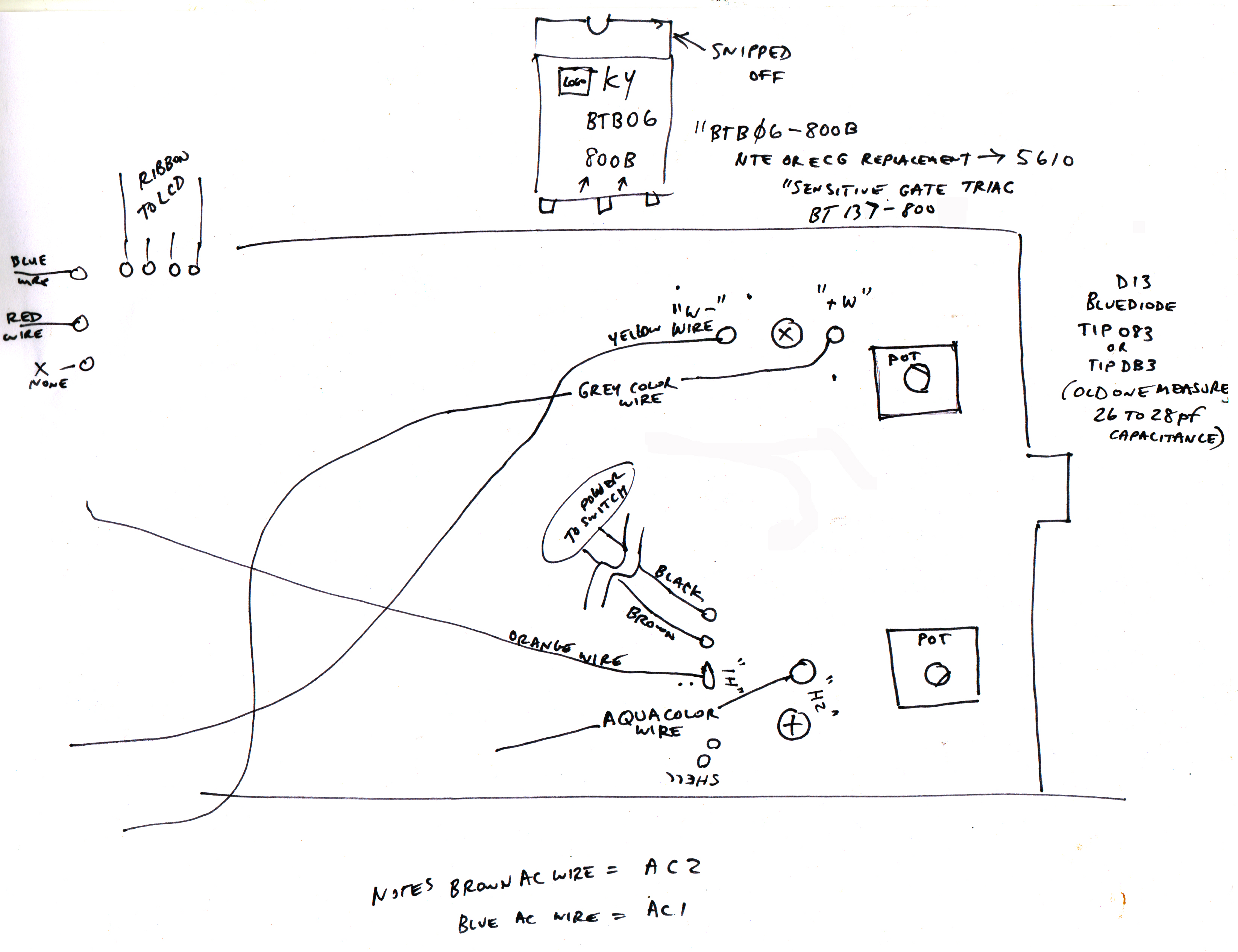
I see a schematic on a video which helped me identify DB3 as a real part number (as I looked through the magnifier I was not sure if it was a D or a O or a B or an 8). I am not affiliated with this video- not my video.
https://www.youtube.com/watch?v=dqsT3PNfj7Y
I suggest opening it up to make sure to correct any mistakes in assembly. I have repaired it and my story/pictorial is herein these files. Contains photos, a text file, 3d printable hole cover STL file and CAD drawing of this part. I created this modification/repair Jan 2018.

|
My GL8018LCD Repair Part A.zip Size : 13704.479 Kb Type : zip |
|
|
My GL8018LCD Repair Part B.zip Size : 14591.316 Kb Type : zip |

|
GJ8018 PCB & Wiring Sketch.jpg Size : 1449.306 Kb Type : jpg |
Doma / Amscope Stereo Microscope (heavily modified)
I use a plastic stereo microscope which is Amscope model SE120 and has 20X magnification. It had a strange design in which I feel it was made Backwards. So I cut it in half carefully and made it Normal.
This microscope was purchased in 6/2018 brand new directly from Amscope (Arrived in a crinkled Doma 210 box.) There were other no-name for the same price, but the photo showed this unit with the rubber eyepieces - that was the deciding factor in going with Amscope. I dont know whether the no-name units came with rubber eyecups or not.
I modified it the same day I received it using a 3d Printing Pen and light gray ABS filament. The body of the microscope is white and I used ABS filament which I already had. I wasnt worried about a color match. I made a big ugly weld and went over and over and over as I wanted it to be super strong. Im sure the DIY weld is very ugly and very strong.
I used a dot placed on the stage as a target (piece of tape with a magic marker dot) - welding the plastic and comparing the dot often to see if it is in the center. This took several tries to get right and I ended up cutting my own plastic welds and re-weldind it until it was centered. This tedious process took about 3 hours and Im pleased that I have a nice straight level NOT-BACKWARDS-ANYMORE microscope. I specifically purchased this to reCAP a Panasonic DVCPRO50 VTR that I own that was just FULL of Bad SMD electrolytic capacitors. In the waiting period for the arrival of the microscope, I have re-done most SMD caps with just a filmstrip projector lens- but was very tedious. I will be using this microscope from now on.
Amscope SE120 (heavily Modded) has a bright single LED and runs on 2ea AA batteries (supplied). I even modified the styrofoam box - so the same microscope fits into its original crinkled DOMA 210 box when not in use. THUMBS DOWN ON A BACKWARDS microscope that came in a wrinkled box with a different brand. I corrected it to be NORMAL and now works good and feels good. The rubber capstan-style up/down movement doesnt hold the position as firmly as I would like. For now it is good enough and holds up/down position good enough to solder/desolder.
I see the very same big-auction-site ad where I bought mine a week ago - it shows qty 810ea sold so far and seems to be a very popular microscope. I wonder if Amscope is a re-brand or the actual mfg?
I see the same microscope "Aomekie" "Amscope" "Doma" and some no-names. My box shows "DOMA 210" I have created this image using Microsoft Paint on a Windows XP laptop. The gray blob represents my plastic welding using 3D Printing Pen and ABS filament.
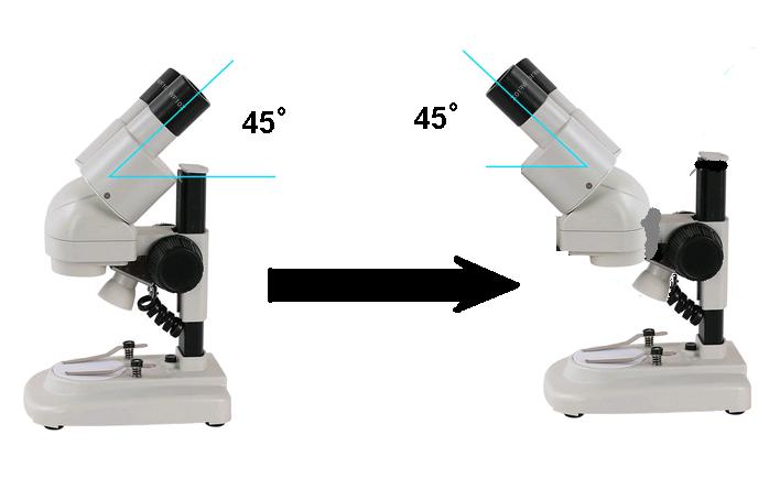
Here is a photo pictorial of my Modification to the microscope. See the above photo shows the eyepieces are facing the wrong direction. My microscope has the eye pieces facing the other way now (took me 3 hours to fix it) and the ZIP files show every step.
Update 8/18/18
As a result of extensive SMD capcitor replacing and using this heavily modified microscope, I have become painfully aware of the shortcomings of using SMD solder paste. Previously, I just thought it was a liquid that had te color of solder and magically turned into solder when heated- this is now VERY aparent to me to be false. As I look at my soldering under the microscope I see that the paste is actually tiny balls (like a bottle full of BBs or ball-brearings and it has a poor quality flux that evaporates and dries out- this flux is unlike traditional soldering flux. The SMD Flux Sucks!!!!! The microscopic balls fly everywhere when you put your soldering tip to melt it. Under the microscope it makes a big mess. MESS MESSS MESS I couldnt believe what I saw under the microcope at 20X magnification. Wiping the excess SMD solder with a cotton swab just smears it everywhere.
To the naked eye, soldering SMD is nice and neat and clean- but under the microscope - I see that it throws microscopic lead balls everywhere on the board and more. Also as I view youtube soldering videos - I am noticing that this happens to everyone and they are oblivious to the lead balls flying while they are soldering SMD. As I watch closely in these online videos I see these solder balls flying and the authors are oblivious.
I havent read or seen ANYONE addressing this issue.
My solution is to vacuum these ridiculous solder balls using a 3d printed attachment for a small Shopvac.
I will chronicle this further down on this page.
|
|
Amscope 120 Backwards Mod Part1.zip Size : 11075.551 Kb Type : zip |
|
|
Amscope 120 Backwards Mod Part2.zip Size : 10220.89 Kb Type : zip |
Vacuum Cleaner Attachment for SMD Solder Ball Cleanup
I have designed and 3d printed the following items using freeware Solvespace and an older Windows XP laptop. I printed them in ABS on a heavily modified Alunar R100 3d printer with a cardboard pizza-box enclosure and Add-on heated printbed. I printed these pieces solid and .1mm resoolution and Elmers Purple gluestick on a plain aluminum heated bed. I used Cura to generate my G-code. My process is painfully slow but gives wonderful results.
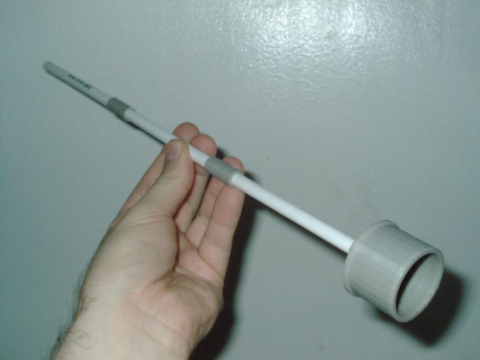
I have included one photo showing the hose attachment and interconnects/couplers for as many BIC pen tubes as I need. Sometimes I use this for cleaning hard to reach machine internals. Sometimes I use it to clean circuitboards Im soldering SMD which throws alot of microscopic solderballs everywhere - even in between solder legs and hard to get to places.
The bic pen tube tip can be with or without the black or blue pen tip. For cleaning microscopic SMD solder balls - using the black or blue pen tip allows for a much smaller vacuum hole- and hence more powerful suction in a small spot.
I dont know where the balls go when sucked up inside the machine- it would be good to invent a solder ball catch filter etc which goes inside the vacuum cleaner. I dont know if the vacuum cleaner bag will catch these tiny solder balls. I dont know whether the vacuum cleaner with throw these solder balls everywhere in your room. Some vacuum cleaners have a bag and others do not. Use your own best judgement on whether this is right for your application or not. Spewing tiny lead soldering balls in your lungs and all over your room - is not what I want for you. Be safe.
Be aware that lead solder paste is absolutely packed with tiny lead balls which get sprayed everywhere as you solder. All over your hands, clothes, floor, walls, PCB, etc. Look under the microscope and you will see Im right.
Use at your own risk.
|
|
Vacuum to BIC pen(s) files Dr Virago Pete 081718.zip Size : 55.966 Kb Type : zip |
------------------------------------------------------------------------------------------------
Electrolytic Capacitors go bad and are the #1 Cause of Failure
(My Personal View)
Electrolytic Capacitors have a rated lifespan of approx 1000 hours or in the case of highest quality electrolytic capacitors 2000+ hours rated. Multiply 24hours in a day x 30days in a month and you get = 720 hours in one month. So really 90days is the rated life of any device which contains electrolytic capacitors. That is one reason why Manufacturers only offer a 90 day warrnty on TV sets etc- if you leave your TV set on continuously for 90days straight - it will most likely survive 90days without fail- so the mfg is fairly safe offering a 90 day warranty.
It
is amazing that so many devices lifespan is greater than 90days - it
really is not supposed to last that long. Care in handling and not
letting a device get too hot - helps extend the life.
My point is that I always unplug my devices when not in use - any device - especially one where it contains capacitors.
24hours x 30days = 720 hours in a month
3 months x 720 hours = 2160 hours in 3 months
There is some truth to power cycles shortening the lifespan of a device. But I still turn my devices fully off when not in use. Some devices have a standby circuit waiting for a remote control command or a pushbutton command to fully power on- but still a portion of that device is on - even when it is "off" My personal view is - it is better to fully unplug it (or switch off power switch to the outlet or power strip) to prolong the lifespan of the device.

|
Eds88Aom.pdf Size : 112.445 Kb Type : pdf |
|
|
EDS Capanalyzer ad.JPG Size : 301.264 Kb Type : JPG |
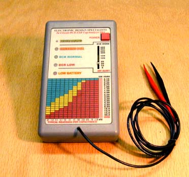
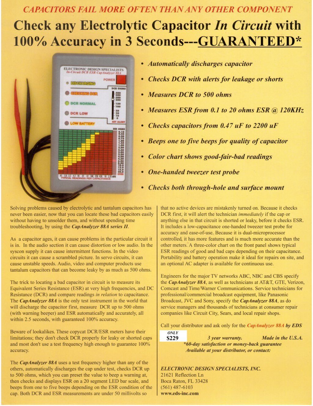
The above is an ESR tester - EDS-88A CapAnalyzer (Series II) which tests ESR (equivalent Series Resistance) for electrolytic capacitors and other types such as tantalum and more. The above file is the user manual. My ESR meter is the EDS-88AII which is a slightly more recent design. The LED bargraph display is easy to read and the alarm sound is settable by the linear potentiometer for sensitivity. The best feature is its automatic self-discharge of capacitors. That was its biggest selling point to me and a big time saver. It will cycle through self-test and several other checks before each and every capacitor check. It is a quick machine and has found countless bad capacitors. An excellent ESR tester.
I already know where the bar graph LEDs should be for small through large capacitors so I dont need to refer to the chart anymore. I just know when the bargraph looks odd for a capacitor then I know it is time to change it. Also comparing the same size capacitor over the same to-be-repaired-board will make a few stand out as being weak or odd functioning. It is a true in-circuit tester. Some bad capacitors show a led towards the bottom of the bar-graph or dont register at all. Slightly weak capacitors can be just a little higher or lower than should be- those are generally not the cause of a failure in equipment operating. It is the capacitors which deviate drastically that generally are the cause of equipment failure to function etc. I always check my new parts too because there are sometimes duds in brand new capacitors purchased in bulk.
Finding a bad capacitor is not about nit-picking if it is in the red or yellow or green area of the chart. A bad capacitor will be blatently bad. If it is not blatently bad then most likely - that capacitor is not causing your equipment to have failed to work.
A bad capacitor will usually be 2x or 3x or more - the rated esr of the rest of the caps you test which are of similar size/type. It will be blatently bad or will give a no reading or a alarm or be drastically different than the rest of the caps.
Cracked or bulged caps or caps which leak gunk (flux) or fluid (flux) are definitely bad and should be replaced- even if they test fine. Some capacitors are glued by the factory - dont mistake glue for leaking flux.
I dont recommend powering up the tester with the red button held down- this disables the self discharge feature (until next power off) because self-discharge is a protection for your esr tester. Touching a charged capacitor can kill the esr tester. Even though it takes an extra second to automatically discharge.
The tester needs no polarity as it functions with self-generated AC frequency and AC is non-polarized. What that means is that you can test an electrolytic capacitor either-way -either polarity of the black/red lead is fine and doesnt matter to the tester which way you connect it to the polarized cap.
It is important not to test huge capacitors with this tester. Just normal size or small capacitors as found in everyday electronic devices like TV radio computers and other ordinary household type equipment. It is not for big high-powered capacitors.
Capacitors generally have a 2000 hour lifespan. It is a wonder most electronics lasts longer than 90days because that is the warranty period. Capacitor's 2000 hour life is 90days. It is a wonder that devices like tv sets last longer than 90days. I always shut off my equipment and appliances and audio/visual gear & more when not in use. Why waste the life of your equipment - by just letting it run idle?
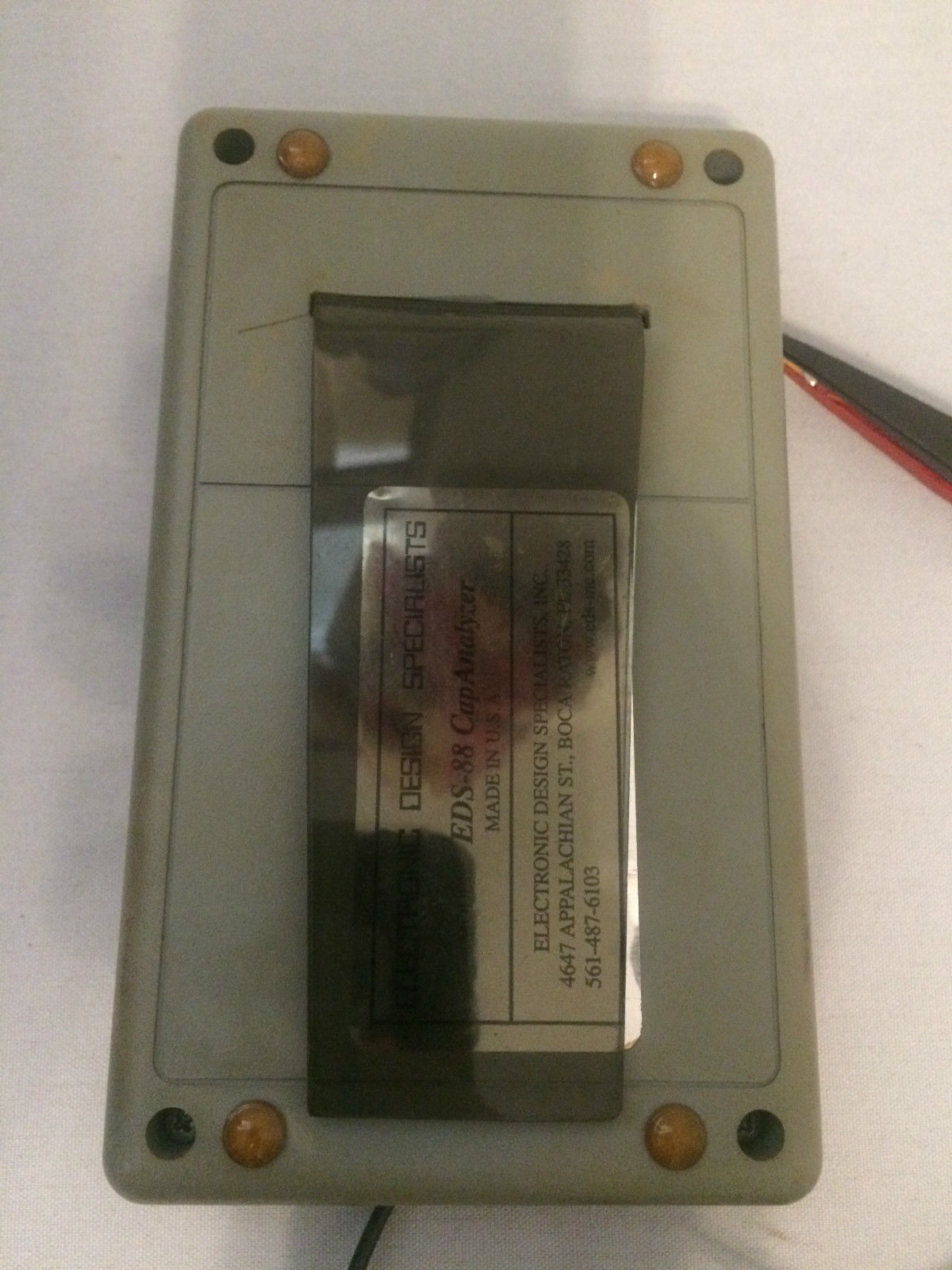
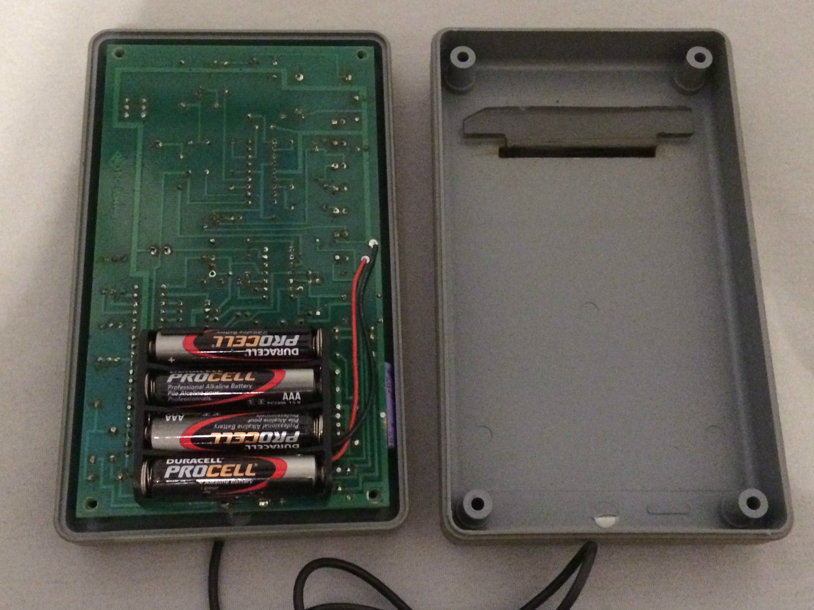
Runs on 1ea 9V battery. Purchased used in 2011 year. A similar tester is Capanalyzer Model EDS-88A
Some notes on difference between model EDS-88A and EDS-88A series II:
The series II has the words "Series II" written on the PCB. The series II uses 2ea PIC chips. The EDS-88A uses 1ea Pic chip and 2ea large LM chips. These 2ea large LM chips were replaced by 1ea PIC in the Series II. The components and layout are very similar. Identical functioning. I have seen a model EDS-88A with a slot cut in the back with a prop-up style holder (See picture file). My newer style EDS-88A Series II does not have this slot or holder.
I see a big-auction-site listing where EDS was cleaning out their inventory of spare parts on 6/22/15 and feel this partial parts list is very important in case of a need to replace blown components. I have copy/pasted this partial parts list here. The ad showed parts used in the Leekseeker89 and Capanalyzer.

|
Text from EDS ebay ad 062215 for spare parts inventory.txt Size : 1.776 Kb Type : txt |
|
|
Big Auction Site ad from EDS for spare parts inventory part A.JPG Size : 60.524 Kb Type : JPG |
|
|
Big Auction Site ad from EDS for spare parts inventory part B.JPG Size : 98.711 Kb Type : JPG |
|
|
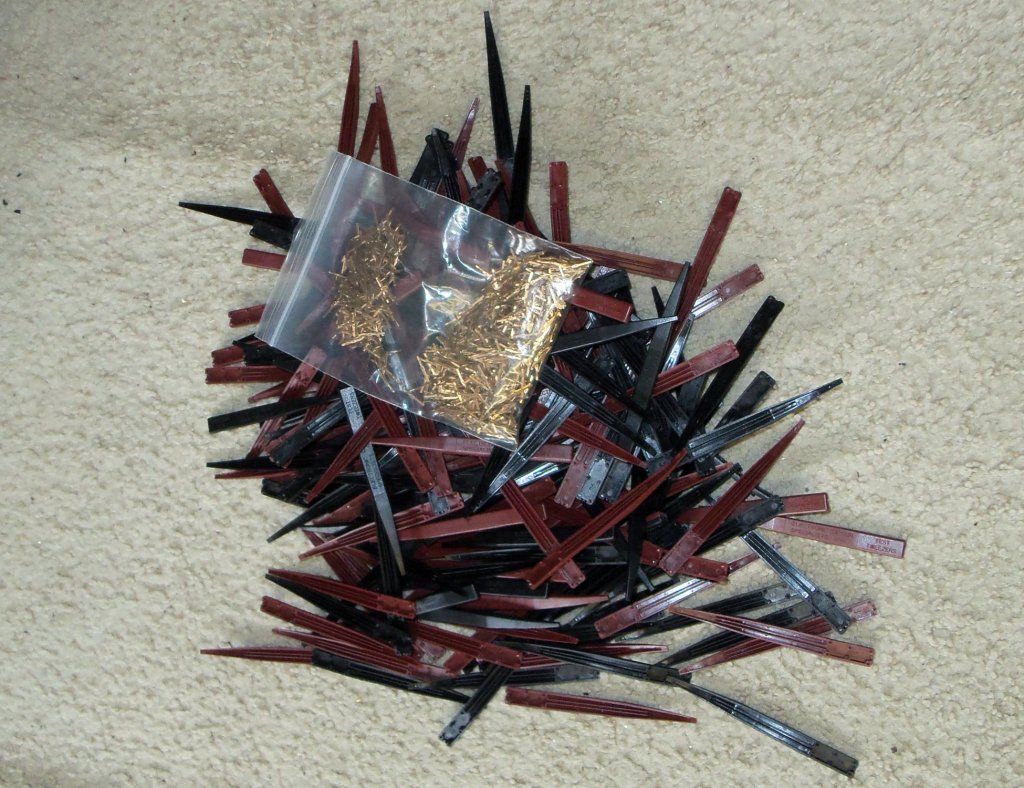
Text EDS Probes Excess inventory Ebay sale 062115.txt Size : 0.751 Kb Type : txt |
|
|
Capanalyzer Probe Kit ad 062215.JPG Size : 75.475 Kb Type : JPG |
|
|
Lot of 100 Probes.JPG Size : 174.149 Kb Type : JPG |
|
|
Capanalyzer EDS88A with slot and Prop-up Holder.JPG Size : 234.715 Kb Type : JPG |
|
|
Capanalyzer EDS88A with slot and Prop-up Holder inside view.JPG Size : 263.061 Kb Type : JPG |
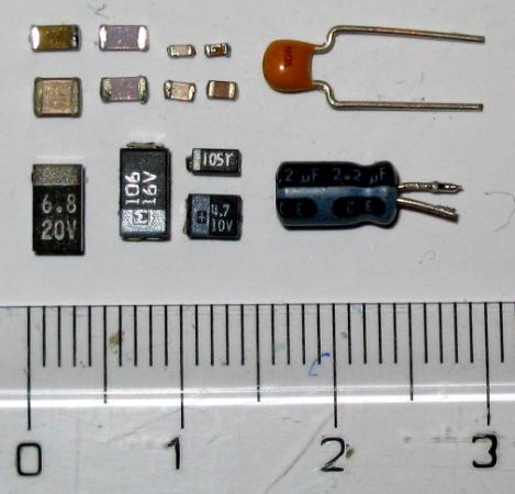
Several photos showing transistors, capacitors, diodes (above pictured)

I received this book for free from a local electronics store that I used to buy parts from regularly in the 1990s. That store is now closed and the remaining branch is too far away to drive to but I occasionally mail order from them still. This book is old and the tattered pages and cover are taped back together. I use this book often. When I suspect a part is bad - I look up the part number in this book and it tells the specifications of the cross reference part in great detail. At the front of the book - a list of available replacement semiconductors is handy. It also contains drawings of pinouts.
ECG parts and NTE parts share the same part numbers and specifications - so when I find that I need a replacement - I will look online or call local electronics stores with a part number. I tell them it can be ECG123 or NTE123 for example. I sometimes can find a replacement part still in its package unused on big-auction-site. It is amazing that one little part can cost 2-10+ bucks each and even so the repair of that device for $10 is money well spent and very cost effective. I sometimes look for a reverse cross reference so I can broaden my options when buying a replacement part. There are millions of numbers that truly are the equivalent part. This book narrows down those millions of numbers down into several hundred part numbers.
The main pupose for this book - for me - is to compare questionable parts and decide if the part is still good. This book has saved me from buying a large quantity of replacement parts over the years. I can key-in on only buying parts that I know are truly in need of replacement.
My cat starting digging at this book 5 years ago and luckily I caught it just in time - before she tore it to bits. The cover and a few pages-in are now taped back together as best as I could. The holes are due to my cat. The worn out pages are due to my extensive use of this guide.
I purchased this tester approx 1997 brand new and been using it for over 15 years. This tester is a full service device and fully tests out-of-circuit/desoldered transistors, Diodes, SCR, LED, Resistors, Capacitors (Capacitance value only - no ESR), batteries, etc. This device helped me repair quite alot of electronics. The only test that it doesnt do is ESR which I believe this machine was made before ESR testing method was invented. I use this tester in conjunction with a 1996 edition manual to look up the cross reference value of nearly any semiconductor. Then I compare those specifications to what this BK Precision 815 Parts tester reads from the questionable part. I have purchased a few NTE and ECG replacement parts based soley on the readings of this tester. It has never let me down and is always correct. I have read alot of questionable parts on this tester and resoldered them back in circuit knowing that this tester proved the part in question was not bad after all. It has saved me from buying replacement parts un-necessarily. I can key-in on ONLY buying a replacement part which are for sure needed.
The above pictured tester shows a rubber protective cover. Mine was one of the first ones made and didnt come with that rubber cover. It still sells for the same price that it did 15 years ago. For the last few SCRs that I tested - I couldnt get my meter to over-range (the first 2 tests pass and the last test fails to over-range). So I ended up buying an SCR twice un-necessarily. I'm starting to think there may be a component inside that has gone bad. Fixing a tester is one of the hardest things to do. You need a tester to test a tester ... and if you rely on that tester and you only have one - then ... I'm not truly convinced yet that it doesnt work for SCR anymore. I will refrain from repairing that which works. It may be that those 2 SCRs fooled it or it may be that the tester has a bad part - I'm still undecided. If the reader has a suggestion on which internal component to check - let me know. The Duoyi DY294 shares many of the same functions - so I am able to test my tester with a tester ... LOL
I remember seeing a bright yellow Clone of this tester on big-auction-site. Unfortuantely I no longer have that photo.
|
|
DY294_V3.pdf Size : 139.275 Kb Type : pdf |
Above pictured Duoyi DY294 Transistor & Parameter Tester (Also Checks many other semiconductors and capacitors etc)
DY294 English manual download above (my tester came with a foreign language paper instructions)
This tester has some unique features which allow me to test parts I could not otherwise test. It also internally scales up the voltage for certain tests- for example it can generate over a thousand volts for certain tests yet only 4ea AA batteries power this tester. It tests alot of parts' parameters so it can be compared to book specifications. For example when deciding whether the part is good/bad - comparison of data found in ECG or NTE semicoductor replacement data books - comparing what you see on this tester can be compared with those listed in the ECG or NTE books for their subtitute cross reference part values.
Some tests for varistors or transistors with internal diodes can be checked with this tester. It is a very handy device for alot of things found in most everyday devices- which previously there was no easy way to test them that I know of. Care must be taken to set the dial correctly and not flip the dial after the part is installed otherwise you can expose a part to the wrong test and apply too much power to the part accidently. Keeping a notebook on how to test a part is important so you can repeat that test the same way next time too. The apearance of this tester is deceivingly simple. It is labeled as a transistor tester but it is so much more than that. It not only tests standard transistors but all of the oddball ones too and many more parts. It is very versatile and performs odd-ball tests that my other testers dont do. There are a few tests that a few of my testers have in common.
On some tests the TEST button is pressed and on other tests the TEST button is not pressed. Read the specifics on whether that test requires the TEST button to be pressed. Note that when the TEST button is pressed - the red LED "HV" next to the TEST button - lights up.
Purchased brand New in 2012 year.
Update 12/14/15
I credit this tester in identifying the voltage on a hard to identify Zener diode. It gave me the voltage and reverse voltage - and was able to match the zener type based in its readings. I know of no other tester which could have provided me with this information. It is a great component parameter tester. Its extreme ability to actually generate high voltages and test components at their high voltage specs (in the case of the above mentioned zener diode 160V) is a very welcome feature. I have other testers whichg identify zeners but thopse testers are only for low voltage parts. This one is very capable. See "Zener Diode Test" on this page to see my procedure notes.
Duoyi DY294 Tester Notes
Test 4ea AA internal batteries condition
(no components connected) turn dial to the right "2a(Ic)" The display shows battery volt (4ea AA batteries at 1.5v each should give you 6volts or better - the tester will work with weak batteries on most functions but some functions require peak batteries to give accurate reading) It is not necessary to press any button with this test.
AC Adapter
6V DC 2A using the jack on lower righthand front panel. + is the center connector. When using the ac adapter - make sure internal batteries are removed.
Voltage Regulator Testing
78XX and 79XX etc insert in 321 holes. With 78XX the regulator faces towards me. With 79XX the regulator faces away from me. Move dial to "78xx" or "79xx" and press TEST button and read display volts. Internal 4ea AA batteries need to be strong for accurate results. For example 7806 installed correctly with good batteries installed will show 06.0V when Test buton is pressed. Make sure your parts legs are free of excess solder or it will "booger up" your test holes as it is a tight fit since the legs just barely fit through the holes.
LED Test
Turn dial to "10mA(Ib) NPN (Put long lead of LED in "C" hole. Put short leg of LED in E hole) The led will shine brighter in other dial positions but this lower power position is safest for the LED as you dont want to burn out the LED - just test it. 10mA is enough to light most average LEDs without harm. Over time/decades of use - some LEDs grow dimmer with age. I suggest that dial is turned without anything inserted. LED should be installed AFTER dial is turned so as to avoid higher power ranges which can damage lower power LEDs. Display shows turn-on voltage of LED. Putting LED backwards does nothing and LCD shows only internal battery voltage of 4ea AAs installed. Typical red LED will show 1.76V for example when inserted correctly. No buttons are pressed during this test.
Zener Diode Test
Use E and C holes. Set dial first before inserting part. Set dial to "200V" NPN. Insert zener diode into E and C. Stripe side = C hole which gives Breakdown voltage when you press TEST button. Insert zener diode with stripe side = E which gives Forward Voltage Drop voltage when you press TEST button. Remove part and move dial to ICEO NPN and then insert diode (both ways) press TEST gives ICEO reverse leakage current. Having good fresh AA batteries installed is important for accurate reading
Varistor "Operating Voltage" Test
If the Varistor's value is 300V or below then use 200V NPN setting.
If the Varistor's value is above 300V then use 1000V NPN setting.
(300V is not a misprint and 200V is not a misprint and 1500V is not a misprint)
Turn dial to "200V NPN" or "1000V NPN" depending on your varistors value (see above note) Locate the capacitance test socket located in the lower right hand corner of the tester. Warning - This is a high voltage test - keep your hands away and dont touch any part of the meter or varistor during test. After dial is set and you have inserted varistor into the capacitor test socket - then press TEST button. The display will show the "operating voltage" on the display. It may vary a little from that written on the part. Release TEST button. Set dial to off before removing varistor. Avoid electric shock by not touching any part of the tester or varistor. This test generates up to 1500volts. Be very careful. I know of no other tester which can test a varistors "Operating Voltage".
Varistors and Disc Shaped capacitors look similar - be sure you identify the part correctly. Only run this test for Varistors.
Polarized Electrolytic Capacitor "Withstand Voltage" Test (medium size or smaller barrel shaped caps)
Locate capacitor holes labeled C+ and C-. Move dial to 200V NPN. Insert the legs of the capacitor into the correct socket hole. The stripe side of the capacitor is the minus side. Read the capacitors voltage and write it down. The way the capacitor is inserted - makes the capacitors value as writton the capacitor itself - faces the wrong way - so writing it down helps you remember - not to exceed the voltage that was written on the cap itself. This is a slow test and takes awhile and is a battery hog - will drain your batteries. Press TEST button and keep it held down until your voltage increases to the voltage written on the cap itself. This meter only tests the "withstand voltage" of the cap. It does not test ESR. It does not test capacitance. I know of no other tester which can test a capacitors "withstand voltage". It will even test capacitors which have a couple of hundred volts "withstand voltage" value.
Remember to discharge the capacitor by shorting the capacitors leads together before and after this test to prevent personal injury from a charged capacitor. Dont touch a charged capacitor's leads or partially charged capacitor. A DC 6V 2A power adapter is recommended for this test (plug into DC6V receptacle located just above the capacitor test socket holes. Otherwise fresh batteries are needed for accurate test (remove batteries when using power adapter plug). Test will quickly drain batteries. A bad cap will not charge or the voltage will cease to climb or will stall or will hesistate. A good capacitor will climb steadily but slowly towards the voltage. Once you reach the voltage - then let go of the TEST button. Do not surpass the voltage written on the capacitor. For example - if the capacitor being tested is a 16V6800uF then do not exceed 16v - after it climbs to 16v on the display - be sure to release the TEST button. I dont know what the consequence of not releasing is - possible capacitor rupture or worse or tester damage or capacitor internal damage - unknown. I suggest only testing it properly.
Transistor PNP and NPN (standard types)
ICEO Reverse Leakage Current test
Turn dial to ICEO (either PNP or NPN depending on which type the transistor data sheet indicates). Use a datasheet or by cross-reference to a substitute candidate data - which legs are EBC or BCE. Insert into the correct socket holes in the tester as appropriate BCE or EBC. Press TEST button. The display should read "000" to indicate that the transistor is not leaky. Anything other than "000" denotes leakage and the transistor is faulty. Remove transistor. Turn dial to off.
hFE (gain) test (3 tests gives gain at 3 fractional amps settings) - make sure your transistor can handle this amperes
Turn dial to hFE 10mA (PNP side or NPN side depending on datasheet specification) Use a datasheet or by
cross-reference to a substitute candidate data - which legs are EBC or
BCE. Insert into the correct socket holes in the tester as appropriate
BCE or EBC. There is no need to press TEST button. hFE (gain) is shown on display. Compare to datasheet.
Turn dial to hFE 1mA (PNP side or NPN side depending on datasheet specification) Use a datasheet or by
cross-reference to a substitute candidate data - which legs are EBC or
BCE. Insert into the correct socket holes in the tester as appropriate
BCE or EBC. There is no need to press TEST button. hFE (gain) is shown on display. Compare to Datasheet.
Turn dial to hFE 10uA (PNP side or NPN side depending on datasheet specification) Use a datasheet or by cross-reference to a substitute candidate data - which legs are EBC or BCE. Insert into the correct socket holes in the tester as appropriate BCE or EBC. There is no need to press TEST button. hFE (gain) is shown on display. Compare to datasheet.
Example C2166 shows "023" which is a HFE gain of 23 at 10uA in socket BCE.
VCE(sat) Collector to Emitter Saturation Voltage (2 tests at 800ma and 2A - not all transistors can handle this amperes)
Turn dial to 800mA(Ic) (PNP side or NPN side depending on datasheet specification) Use a datasheet or by
cross-reference to a substitute candidate data - which legs are EBC or
BCE. Insert into the correct socket holes in the tester as appropriate
BCE or EBC. There is no need to press TEST button. VCE(sat) is shown on display. Compare to Datasheet. (be sure your data sheet shows it can handle this 800mA before testing) Batteries must be fresh for accurate results (otherwise remove batteries and use Ac adapter 6VDC 3A)
Turn dial to 2A(Ic) (PNP side or NPN side depending on datasheet specification) Use a datasheet or by cross-reference to a substitute candidate data - which legs are EBC or BCE. Insert into the correct socket holes in the tester as appropriate BCE or EBC. There is no need to press TEST button. VCE(sat) is shown on display. Compare to Datasheet. (be sure your data sheet shows it can handle this 2A before testing) Batteries must be fresh for accurate results (otherwise remove batteries and use Ac adapter 6VDC 3A)
Diode (standard types) Reverse Breakdown Voltage
Turn dial to ICEO(2000uA) Insert diode into E and C (either PNP or NPN side of dial will work but - or + on display may be opposite) For example on 1N4003 diode turn dial to npn side ICEO(2000uA) stripe of diode goes into C hole. Non-stripe goes into E hole of test socket. Press TEST button. Display shows "000" leakage. Remove diode and reinsert opposite (stripe goes into E hole and non-stripe side goes into C holeof socket) Press TEST button shows "1252" Reverse Breakdown Voltage (weak batteries 5v) Remove diode and turn dial to off.
Dual Fast Recovery Power Rectifier
Turn dial to ICEO(2000uA) NPN side of dial. Insert middle leg into E of large socket. Touch side let to C raised metal contact. Press TEST button. Read display. Release Test button. Rotate Rectifier keeping the middle leg in E hole. Rotal so the other outside leg touches C raised metal contact. Press TEST button. Read display. Remove Dual Fast Recovery Power Rectifier. Turn dial to off.
(Note turning the rectifier such that the middle pin touches C raised metal contact and the outside pin (1 test for each outside pin) goes into E hole. Press TEST button gives "000" display. Remove Rectifier. Turn dial off.
Example MOSPEC F12C20C gives "000" leakage result and "1257" and "1257" reverse breakdown voltage result (weak batteries 5v)
Transistor Parameter Testing Note
Basic Functional Testing transistors can be accomplished by Gain (HFE_ and Leakage for most transistors and it will catch most issues. This next section is about advanced transistor testing "parameter" testing.
The parameters of a given transistor can be determined by inserting the BCE legs of the transistor into non-matching BCE combinations of the socket (BEC, CEB, EBC, ECB, etc many combinations). This produces a wide variety of test results according the the mismatching of leg to socket hole mis-combinations. This "mismatching is not arbitrary and it is not done willly-nilly or random. Follow the below instructions step by step in order to see the transistor "parameters" (I will document this later - to be continued)
odd transistor types
FET
SCR
Triac
high voltage non-polarized disc capacitors
AC filter capacitors
Too many to list (this is a work in progress)
HP 990B SMD tester
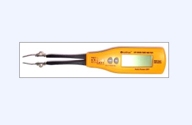
is a Resistance / Small Voltage / Standard Diode & Zener Diode /small battery / Capacitance (not ESR) tester which has built-in tweezer probes (and included add-on handheld probes). I use this occasionally when I work on surface mount boards with very tiny soldered-in components. The best feature about this tester is its ability to identify Zener diodes voltage rating value (not as accurate as my other tester but good enough to determine if a component is blown). Another unique feature is with the push of a button the tweezer tip polarity changes opposite which makes testing standard diodes simpler as the buttonpress allows testing a diode in both directions easily.
For example when testing a brand new in the package 4.7v Zener diode this tester will give a value of 4.01V and .063 reverse. Good enough for testing purposes - to determine if a zener is good/blown.
It has the functionality of a VOM multimeter with some additional features ( for example like zener test ) - however it is only for small voltage sensitive rating parts - not for use on big voltages or powerful components. Runs on 2 AAA batteries Purchased Band New in 2012 year approx.
Update 12/15/14
I suggest removing the batteries immediately after use. My first unit worked just fine for 1 day and one day later was found dead on a few but not all functions - and exchanged by a kind China vendor. I can only suspect the internal batteries caused some issue. I have had nothing but good service from my second unit, and I always take out the batteries. There is no on/off switch.
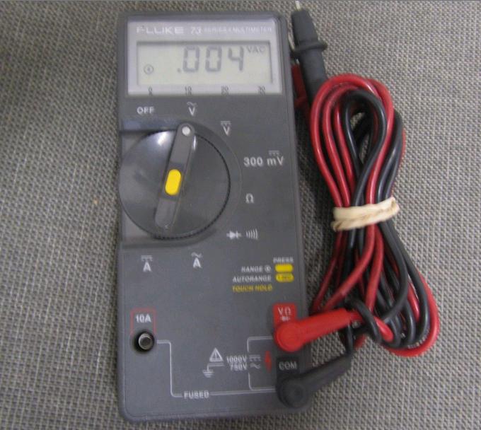
This is a very old tester and works very well. I trust it to give me the correct display of Voltage AC or DC or Ohms or Amps or Diode Test or Continuity Beep. It is easy to use due to its autoranging and autopolarity. It runs off one 9volt battery which lasts for more than a year of my use. I own several multimeters or VOM meters but this one gets used the most and I keep it handy to test batteries and electronic components etc.
My Fluke 73 is dead-on accurate.
For example I noticed a year ago that my AC power was higher than it was supposed to be. I initially caught that over-voltage when I tested the outlet with a Killawatt meter (also very good) and then I doublechecked the voltage on my Fluke 73 - same reading. When I called the electric power company to report 126.5V AC from my outlets the lineman that arrived confirmed this fact and said that he also measured 126.5v AC and he said that it is high but still within electric company guidelines - no repair done to the line. (Illinois USA AC varies nowadays from 123 V AC to 126.5 V AC and it is a bad idea to plug in older appliances and electronic gear without stepping down the voltage to within range of what the device requires.)
The Fluke 73 is a professional tester and is trusted by many millions of technicians.
|
|
AD1440002 Post Card Side1.jpg Size : 359.495 Kb Type : jpg |
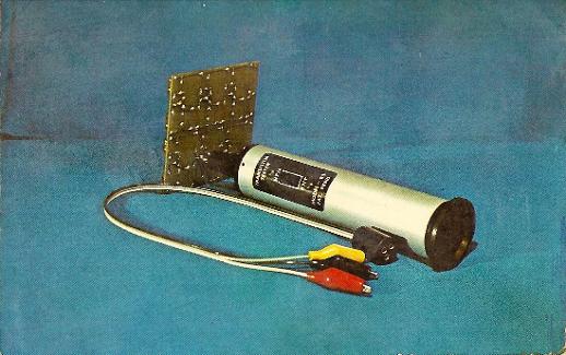
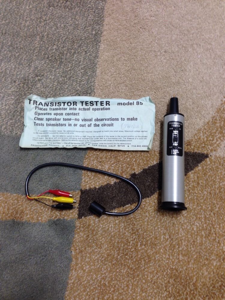
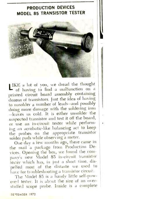
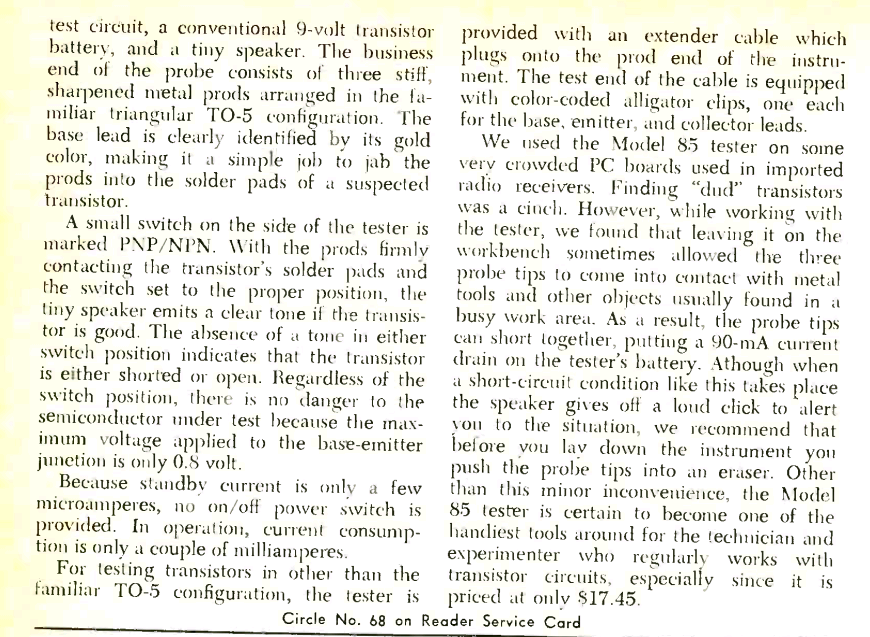
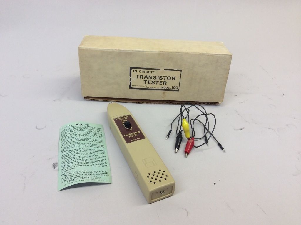
It doesnt test all transistors but tests enough that it is a help when checking for transistors that are bad - without desoldering the transistor. It has a brushed metal round case that resembles a microphone. The back cap is a press-fit and inside is the tiny headphone-like speaker and the speaker is moved outside the case dangling to replace the battery. The plastic cap on mine is original but doesnt hold itself in place- the previou owner used a piece of electric tape for a press fit which was unbelieveably very very very tight. I used a piece of celophane tape as a spacer for now. A set screw would be a better way to do this.
It runs on 1ea 9V standard rectangle battery and I always take out the battery because there is no power switch.
|
|
Production Devices instructions Mod 85.txt Size : 1.003 Kb Type : txt |
|
|
Production Devices Mod 85 w instructions.JPG Size : 143.481 Kb Type : JPG |
|
|
Production Devices artcle IC tester Page 1.JPG Size : 60.407 Kb Type : JPG |
|
|
Production Devices IC Tester Article Page 2.bmp Size : 1624.9 Kb Type : bmp |
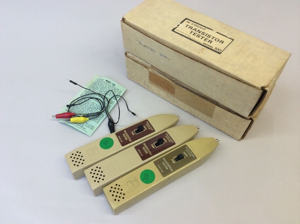
It doesnt test all transistors but tests enough that it is a help when checking for transistors that are bad - without desoldering the transistor. Battery is accessed by unscrewing 2 screws and separating the case halves.
It runs on 1ea 9V standard rectangle battery and I always take out the battery because there is no power switch.
|
|
3ea Transistor Testers model 100.JPG Size : 75.384 Kb Type : JPG |
|
|
Production Devices instructions Mod 100.txt Size : 1.666 Kb Type : txt |
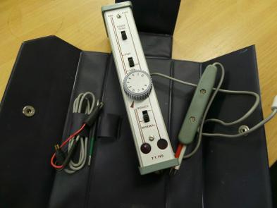
This tester works very well to locate dead or shorted transistors in circuit. It is a 2-handed IC tester. One hand is holding the body of the tester and pointing the sharp green probe and touching it to the BASE of the transistor (usually the middle leg but not always) and the other hand is holding the red/white probe and touching it on the EMITTER and COLLECTOR of the transistor. One feature I really like is that the internals of this tester are alternating back and forth between Base and collector - so it is not important to know which one is which while testing. The result is a blinking LED if the lowpower transistor is good. The blinking LED is due to the internals switching back and forth between collector and emitter on the red/white probe. This feature is a big time saver. I'm going to call this feature self-permutating as it hunts on its own for Emitter and Collector on the red/white probe.
Quickly scanning transistors is easy and can be tested in just a few seconds each. If the transistor doesnt flash then adjusting the dial to try and find a setting where a flashing LED is observed or switching the NPN/PNP switch is needed. If the LED flashes then the transistor passes the GO/NO GO test.
The manual shows how to test diodes and power transistors.
Some Words of Caution
The power jack is not for connecting power (runs only on internal 3ea AA batteries). The power leads which are colored with a black wire and red wire are not power leads at all. Never connect any power to the power leads. The red and black wires (and alligator connector) and power jack is for testing power tansistors. The red and black wires are not needed for testing small signal transistors. There is another typo in the manual - the lightbulb does not light up during self test - only the LED. The lightbulb lights flashes when testing power transistors and pass. Probe leads are very sharp and hazardous - CAUTION
It runs on 3ea AA batteries and I always take out the batteries because there is no power switch. Also The probe tips are very very sharp and hazardous. This tester was made in the 1960s and I was lucky to find in pristine condition in 2014.
|
|
AVO TT169.pdf Size : 1510.668 Kb Type : pdf |
|
|
TT169 Schematic.pdf Size : 585.949 Kb Type : pdf |
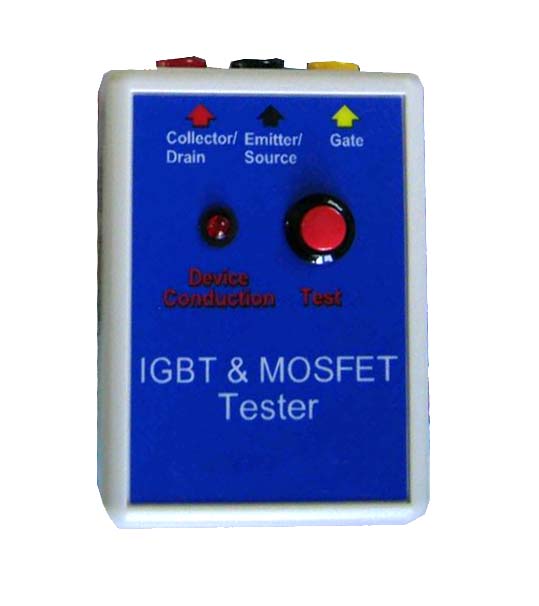
I use the above pictured IGBT & Mosfet tester when I test the high power IGBTs. It has three leads and alligator clips. The LED lights or doesnt light to show correct or incorrect operation of the IGBT when the red button is pushed. It is a nice easy way to functionally test these parts. Some IGBTs fail catastrophically (melted/burned etc) on devices --to-be repaired- but others fail and there is no outward sign that the part is internally bad. The click sound and the red light means it is a good part. I have run into bad parts - and the tester either stays lit or stays off or doesnt respond to the button press- which means the IGBT under test is bad. It can also functionally test Mosfets. Runs on 1ea 9V battery. Purchased Brand New in 2011 year.
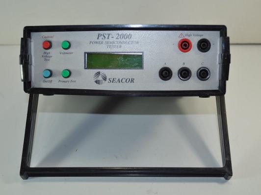
Consolidated Electronics Inc Semiconductor Tester model PST-5000 and
Seacor Semiconductor Tester model PST-2000 (pictured above)
(also written as PST5000 or Semi Conductor Analyzer. Also sometimes the company was written Consolidated Electric and their website was Con-elec dot com and I see it is down as of recently and their 800 phone number doesnt work and says "disconnected or no longer in service" as of 8/14)
I have recently (Aug 2014/ March 2015) purchased these used testers in fixer upper condition (disassembled and missing parts) Both are nearly complete with minor things missing such as 2ea power adapters and 1ea rear panel and 1ea battery pack. I have reassembled them and have plans to create a homemade power pack and ac charger as close to original as I can fabricate in my shop. I have enough parts between the two units to fully restore both by comparison.
Consolidated Electronics PST-5000 and Seacor PST-2000 are "sister" units - they bear a diferent namebrand but truly are alike in many ways.
The best feature is in-circuit testing of transistors, diodes, scr, triac, mosfets, and many other parts. For some tests the leads can be attached to the semiconductor in any order - it will self permutate the test leads and display the pinout and identify the attached part. The display shows a text description and pinout. At powerup it performs a self test for 30seconds. The testing is performed by holding down the test button for approx 30 seconds after which the test results are displayed. There are 2 tests available Primary Test and High Voltage Test (a third onboard function is voltmeter). It must pass both tests for the part to be "good"
I look forward to the completion of the homemade battery pack - 2ea internal 12v DC packs (10ea x AA Nicad) as this will allow 4-8 hours testing time. The high voltage test puts the packs in series (24V). The Primary Test uses the battery packs in parallel (12V). Pressing the High Voltage test climbs the voltage supplied to the part being tested until it fails or passes (nonharmful to the part being tested - low current and autosenses any changes in the part). The PST-2000 has an upper limit of 2000V and the PST-5000 has an upper limit of 5000V. I dont foresee ever using the maximum high voltage capabilties as capacitors/other parts I test are no-where near that high voltage. Even so it is a very capable tester and easy to use for my low power/mid power component testing.
In many ways it is as easy to use as the "caseless semiconductor testers" that are popular as of this writing for less than $25 on big-auction-site (I have one too see elsewhere on this page - that one only works for out-of-circuit desoldered part testing). These PST testers perform high voltage tests and out-of-circuit and In-circuit tests - that is a drastic advantage over the inexpensive testers. The in-circuit testing capabilties are super great and IS THE reason I bought these. Well worth the effort and expense/cost to purchase and fix these 2ea formerly abused units received in disrepair.
Unknown mfg date and age - I estimate these were manufactured in the early 2000s and probably new costed more than I could afford.
I have tested both units with a makeshift power supply and both power up equally well and seem to be fully functional. My repair notes and photos are listed here.
Update 6/22/15
I went ahead and ordered some parts and pieces in order to complete my units. I ordered 2ea NiMH 12V 1800mAh battery packs, ABS 3/32" (.093") textured sheet total cost approx $27 so far. I plan on cutting the ABS sheet to size to make a back panel - I will use a China 40W laser engraver to cut it cleanly. The 2ea NiMH battery packs are 2x5 arrangement of AA cells. I will snip off the connector (Tamiya RC style) and solder connect the original connecrtor and then heatshrink insulation over the solder joint. Battery packs from China take awhile to arrive and was a good deal at approx $10 each. I will order replacement battery packs for the second unit at a later date. This will allow me to do some testing on both units to make sure they operate fully and figure out the ac charging plug and voltage/amps needed.
(847) 454-7858 between 11am and 7pm daily
drviragopete@att.net
Dr Virago Pete
I received 2ea 12V 1800mAh NiMH battery packs from China yesterday and have installed these in my PST-2000 battery pack assembly to replace the 2ea severely corroded NiCAD packs 12V 650mAh. The main thing was to remove the 4ea rivets securing the aluminum retainer which holds the batterys in place. I used a Dremel tool with a cutoff wheel to grind down the rivets backside (the aluminm side) and then when the rivet was flush with the aluminum - I just grabbed he rivet with a vise-grip and pulled the rivets out. I used 4ea 6-32 philips head screws and 4ea 6-32 nuts to secure the aluminum retaner using the very same holes which were previously riveted. THe screws allow removal of the aluminum plate for future battery pack replacement. SInce the rivets were placed so close to the bend- I had to modify all 4ea nuts to be very flat on one side- that way the nut sits right next to the aluminum bend. If I didnt grind the nut - then I wouldnt be able to fit it using the same holes. This is a nice elegant solution. I used a vise-grip to hold the nut while I useed a Dremel tool to grind it on one side. I also used some foam leftover from packing materials which hap[pened to be the right kind of foam. THe original foam had all kinds of dried gunk from leaking batteries. I put new foam inbetween the batteries - it is very much like original. The only thing I have left to do is cut the Tamiya style plugs off the new battery packs- and solder on the original plug with wires (scavenged off the corroded Nicad packs) and then heatshrink tube over the solder joint. Im very glad it turned out so well - I was thinking about this for a long time and its nice to be so close to completion. I look forward to using my semiconductor analyzer.
The soldering is done - this was very critical as the polarity of the plugs needs to be correct - otherwise the tester can be ruined by hooking up the 2ea internal battery pack's polarity backwards. I double checked my notes and the red/black marker marks on my board. Heatshrink tubing was put on over the solder joints.
I ended up cutting the end off the Zip Drive 5V ac adapter and soldering it onto a 12V 1Amp ac power adapter wall-type. These ac adapters were purchased second-hand and so were expendable. At this time I have tested both PST-5000 and PST-2000 with the same battery pack charged for a couple of hours. They seem to work the same. I am charging the pack for a few more hours- I still have to figure out how many hours to fully charge. The battery packs as arrived from China had minimal power stored. One was at 11v and one was at 10.5v when they arrived. I tested that minimal power and it wasnt able to boot the PST units - but the backlight did light up with that little charge.
See my zip file containing pictures of this PST2000 battery pack rebuild here.
|
|
PST2000 Battery Pack Rebuild.zip Size : 4156.592 Kb Type : zip |
Update 6/26/15
Im glad to have gotten pretty far along on the PST-5000 replacement battery pack. My 12"x12"x.090" ABS sheet arrived today and I looked through my inventory of metal and plastic cutoffs and pieces I scavenged off of misc things a long time ago. I saved a scrap piece of aluminum in my inventory for years - I dont know what it came off of originally - probably a scavenged for parts old dot matrix printer. Years ago people threw tons of crt moniutors and dot matrix printers in the trash and I scavenged some for parts and gears and motors and screws and nuts/bolts etc. Thats where this aluminum sheet came from - scavenged by me personally and saved - for someday possibly being useful for something. This sheet of aluminum was a pretty close match for the original thickness. The original PST-2000 battery tray was made form .030" aluminum and my scrap piece of aluminum was .040" thickness. Pretty darn good find and I made a replacement battery tray as close as I could reasonably make it. Im pleased with the end result.
I used a Delta scroll saw to cut out the ABS sheet after measuring the front faceplace (and tracing it) from the PST-5000. I filed the edges with a fine cut file. It is nice and straight and fits well into the PST-5000 case.
I used an unknown make/model of sheetmetal sheer to cut out the scribed lines and magic marker lines which I transferred from my paper template. This sheetmetal sheet cut nice and straight and otherwise I would have to use a bandsaw or nibbler. The sheetmetal sheer is very small and is a table mounted device with a pull-down lever - which has a shearing action. It made easy work of this project. I filed the edges and planished the edges which curled a little bit - I planished it down using a modified sawblade retoother (unknown brand or model) which I made a new die for (a long time ago) and it straightens sheetmetal beautifully.
I looked through my punch die set and I didnt have a 3/4" punch as my set of dies only goes up to 1/2". This handheld model punch I modified ( a long time ago) to be table mounted and I added a long lever to make punching sheetmetal effortless. (See my links above if you like these tools and want to make on e of your own - my CDROM plans show you how I modified it) I made the battery tray's center hole much wider than 1/2" punch diameter by nibbling out a larger diameter. The make-shift hole is decent and will easily fit the battery connectors through this hole.
I used a vintage DI-Acro finger brake press to make my bends - I did my best to compensate for the thicker metal than original. It is a slightly wider and longer and taller than the original - this is so the battery will still fit in there and not an interference fit. I made my paper template slightly larger in all directions than the original PST-2000 aluminum battery tray.
The holes where the mounting screws go - I cannot punch those because it is too close to the bend. I didnt want a sloppy bend - the holes can affect the bend quality. I will manually drill out those four holes later.
Also yesterday, I was charging up my completed PST-2000 battery pack and I tried it in both PST-2000 and PST-5000 and worked fine - the 4 hour charge was excessive because I listened to the battery pack (at 4 hours of charging) and it was fizzing like a glass of soda. This tells me that the 12V DC 1Amp wall adapter I used was WAY too much amperage. Based on my battery capacity of 2ea 12V DC 1800mAh internal - I estimate the 12V DC power adapter ideally should be around 200mA or less - which would take 5X as long to charge - but it would heat up the battery substantially less. I need to find a 12V DC power adapter because if I continue to brute force this battery pack - the battery capacity will be diminished or the PST unit will be harmed. It just was WAY too much amperage for charging - it doesnt seem like there is internal regulation of charging amperage or current limiting. The solution is just to use a lower capacity 12v wall adapter next time.
|
|
PST-5000 Replacement Battery Pack Build Part A.zip Size : 4807.5 Kb Type : zip |
I made a test fit of the aluminum battery tray onto the back of the installed blank ABS rear panel - before any drilling and used magic marker/6" dial caliper to see where the holes should be. I used a center punch to make sure the drill bit didnt wander. Then I drilled only the aluminum battery tray 4ea holes.
I drilled the 4ea holes in the plastic one at a time - using the drilled battery tray to keep the drill bit on targetwhile going through the plastic panel - installing the first nut/screw and then drilling the next one and installing that nut/screw - to keep it in perfect alignment - so none of the holes are crooked or misaligned. Also I used a tapered deburring tool after the drilling to make sure the holes are neat and free of jagged edges.
It turned out pretty well - and if I didnt tell you - you would think it was made that way from the factory. I stacked the PST-5000 and PST-2000 for a side-by-side comparison. I saw a photo of a PST-5000 which was for sale on big-auction-site and was just too expensive - but that one showed a rear photo of the PST-5000 - and I used that saved photo to make my replacement rear panel similarly - I noticed the screws are farther apart - from my own PST-2000 original tray - so on my PST-5000 batrtery tray - I also made the screws wider apart. I think the reason is - the power jack is the center on the PST-5000 whereas the power jack is on the left on the PST-2000 (I havent decided where that photo was a modded one or factory stock that way because it had a 4-pin connector on the rear panel ???). I havent decided whether Im going put my own power jack in the center or top left. I still need to purchase the 3ea 3-pin connectors and the power jack and the 12V 100mA to 200mA AC adapter and also 2ea NiMH battery packs. So I have a ways to go in small purchases - but the hard part is done - the back panel and aluminum battery tray are built and it looks decent and good - its looks professional - like a factory made it. I did my best.
|
|
PST-5000 Replacement Battery Pack Build Part B.zip Size : 4836.344 Kb Type : zip |
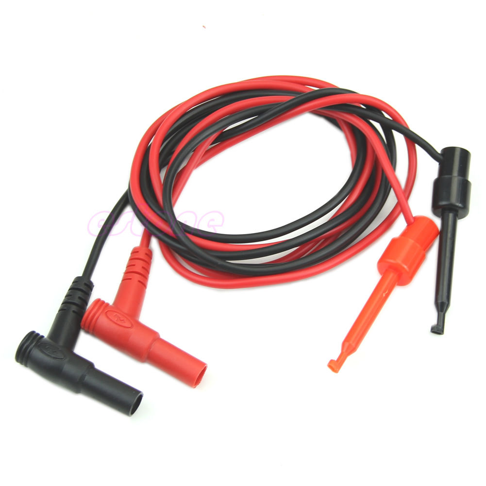
I received 4 pairs of "Banana PLug to Test Hook Cable Probes" ordered from big-auction-site and came from China. I ordered 4 pairs due to needing 6 total wires for both PST units. Also a spare set was ordered for use with my Lissajous tester. The pair of cables is red/black and I plan on using all red on one unit and all black on another unit. The lissajous tester will get the red/black pair. I paid $1.82 plus $.39 shipping for each set. I pay a whole lot more when I ship something even within the same state of Illinois. It was a remarkably low price. I tested one set of clips on the PST-2000 for about 1/2 hour going through about 30 various transtors and N-channel mosfets etc. I like these clips they work well and allows for hands free holding of the parts. The PST units require the test button to be held down during the test - so grabbers or alligator clips is necessary. Here is a photo of the test leads.
|
|
Banana Plug Test Hook Grabber.JPG Size : 79.841 Kb Type : JPG |
|
|
Misc Pics PST-2000 and PST-5000.zip Size : 2073.68 Kb Type : zip |
|
|
consolidated_electric_pst_5000.pdf Size : 152.351 Kb Type : pdf |
|
|
PST-5000 Brochure.pdf Size : 1080.333 Kb Type : pdf |
|
|
PST-5000 as received 101714 part A.zip Size : 10535.688 Kb Type : zip |
|
|
PST-5000 as received 101714 part B.zip Size : 9347.491 Kb Type : zip |
|
|
PST5000 & PST2000 My Repair Notes April 2015.txt Size : 10.49 Kb Type : txt |
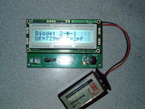
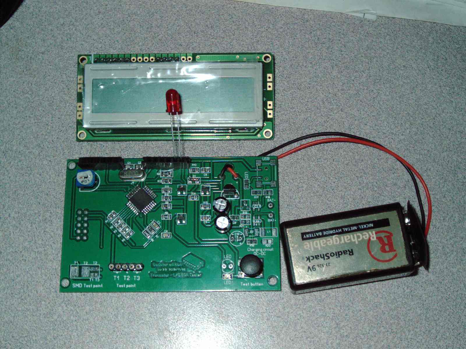
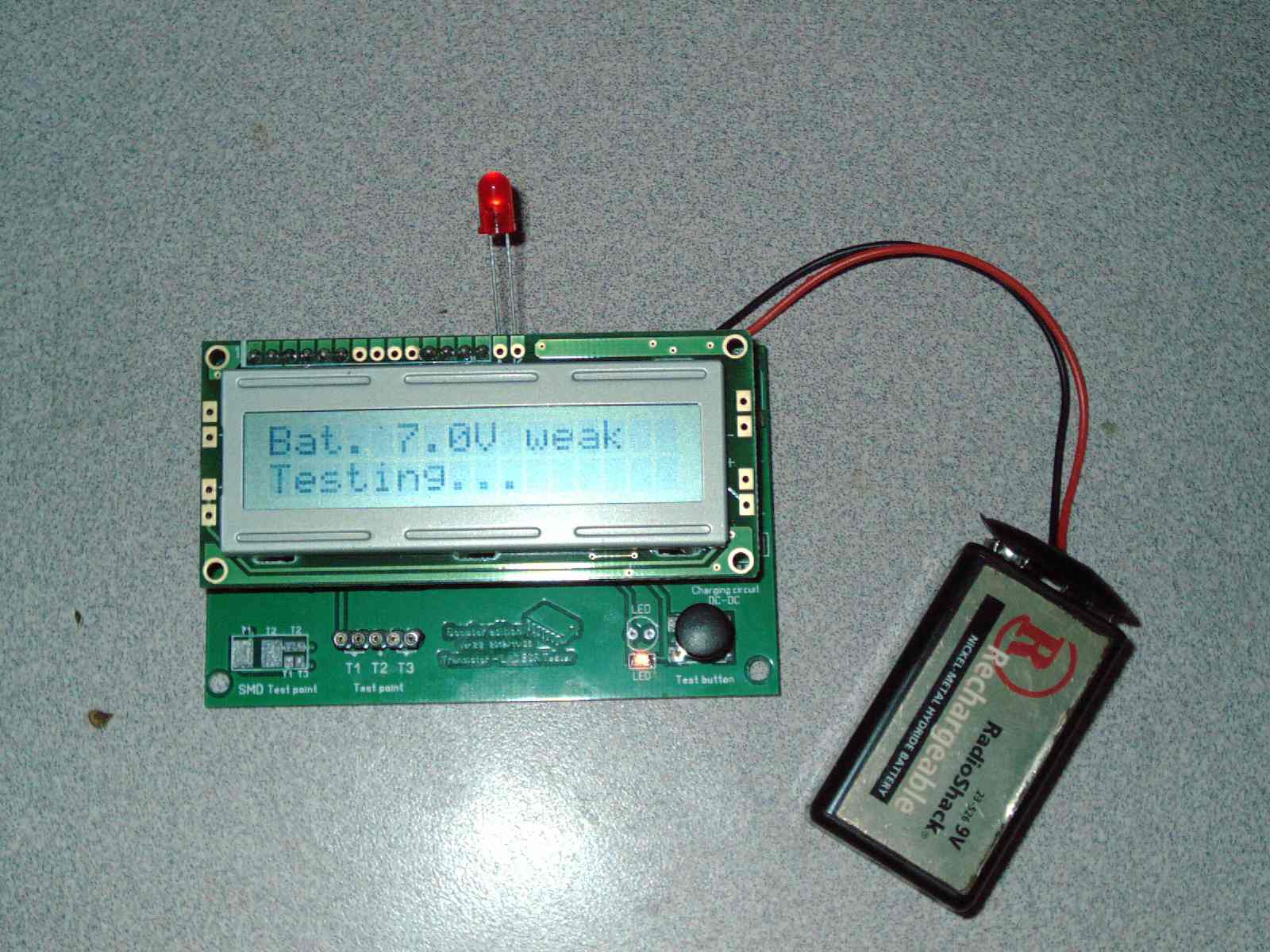
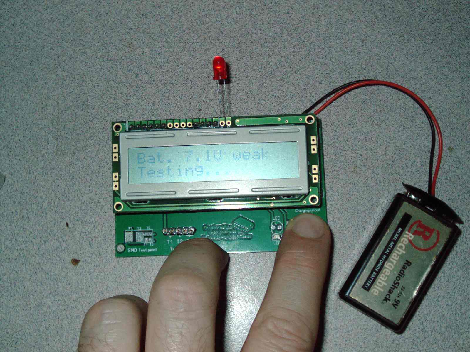
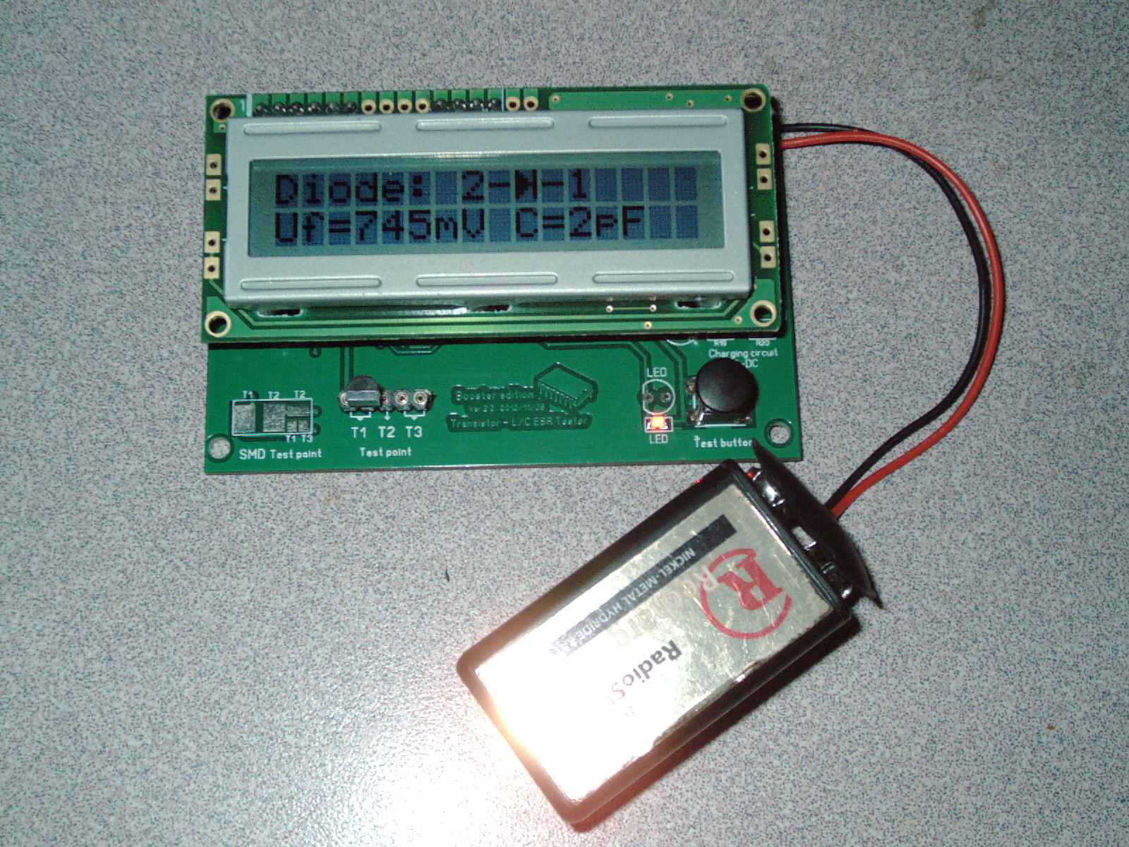
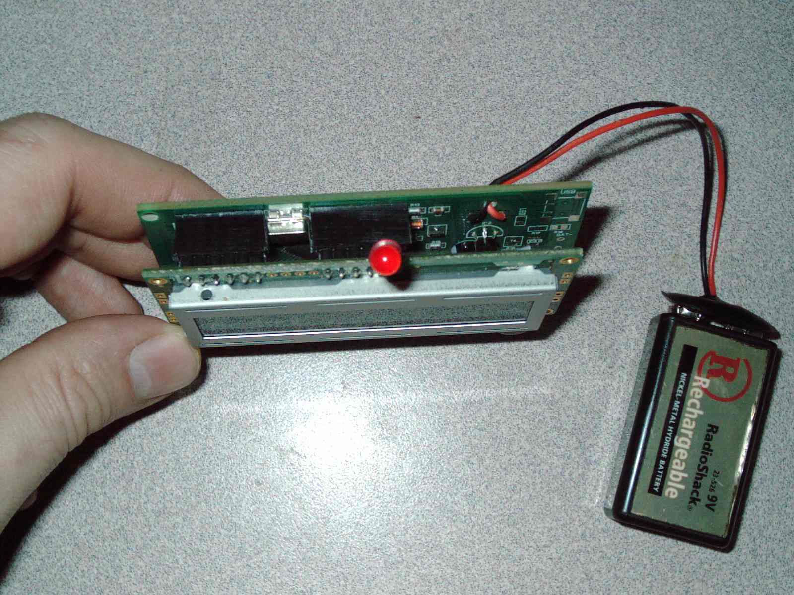
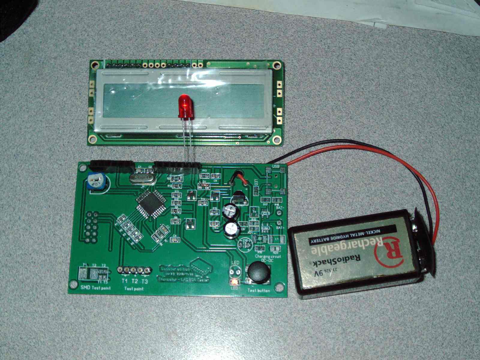
Caseless LC/ESR Component Tester PCB Booster Edition ver 2.2 firmware 1.02K
Purchased from big-auction-site approx end of 2012 for about $20 from China. It is a very common tester with some good features. It doesnt do in-circuit testing or thorough transistor testing. Leakage testing - it doesnt do that either. It does quick component identification including pinous of the lead order BCE EBC ... it does that very well. Even so I just dont find the information that it gives to be useful. When I check a component I compare the book specifcations to the readings of the transistor. I find that measuring leakage of a transistor is very important and this tester doesnt do that. Some newer style big-auction-site testers do measure leakage. But I have been using my BK815 for years and a cheap little tester is no comparison to a profesional arsenal of testers. Even though this less than $20 tester is well worth the money paid. It sits in a small box very little used.
I decided to post my knowledge on backlight for this 1602 LCD display. The tester is a battery hog and NOT HAVING a backlight makes your battery last a whole lot longer. But this simple LED mod which basically costs nothing - every electronics hobbyist has an LED to spare.
The short end of the LED goes on the very end of the single-inline-connector (see pics). The longer LED lead goes on the second to last hole of the single-inline-connector. This demonstrates a 1602 backlight or non-backlight version and which pins (the last 2) are for the backlight. For non-backlight LCD - these 2 pins are missing. A simple backlight is putting a standard LED on the side of the LCD module held in place with a dab of epoxy or silicone caulk. Thats my "CHEAP Backlight Mod" for your Cheap $20 component tester. Otherwise just use a 1602 backlighht edition LCD module and plug it in. It will work just fine but the battery will drain quicker.
This tester uses a standard 9v battery. I normally use a rechargeable battery for everything and these have less than 9V just because it is rechargeable and they produce less voltage than standard batteries do. The tester works with a battery of 6.9volts or higher. 6.9 volts is the bare minimum battery power required.
The side of the LCD module has pairs of empty copper islands - this is where the LEDs go and they face inwards towards the LCD side to light it up. Of course with the 2 missing pins - no power would reach those LEDs - so the user would have to provide those missing pins. The LED lit up shows where the power for the LED or multiple LEDs comes from the last 2 holes on the single-inline-connector. So really this LCD module can handle 4ea LEDs (2ea on both sides of the LCD)
I dont plan on modding my own tester. Like I said the tester is a battery hog and adding LEDs just shortens the battery life even further. Its fine just the way it is. Good enough for occasional use - identifying some oddball transistor or seminconductor that I cant find in any book and knowing the pinout. At least it tells me what the part is and does a quick check - most of the time that is good enough to determine if the part is "probably a good part"
A unknown three legged part will not be identified or will be identified as a resistor or some other oddball display. In that case I know it is a bad part. Its a darn shame if at that point I couldnt find it in any of my books and I had to rely on the tester to identify it. If it cant identify it or gives an obviously wrong identification (3 legged part only sensing at 2 pins etc) - its probably blown/bad part. Its a very rare thing for this tester not to be able to automatically identify a part - even in a rudimentary way - at least it tells you what the part is - useful for small low power semiconductors.
To a complete novice - the information provided for semiconductors inserted seems "WOW look at all of that infromation" but truly almost none of that information is useful. It doesnt give the specifications of the part which are useful for determining if the part is weak or blown or defective. It often doesnt correlate to the book specifications. It gives the novice the impression that the data is the part specifications- no it isnt. Its not all that useful. But it can be used when no book specifications are available and a quick ridiculous novice check is all you can do to an unknown part. If it is blown - the display will mis-identfy the part as something quite obviously wrong such as a resistor or capacitor - when in fact it is a three legged part- because something inside the component is shorted or crossed or weak or damaged in some way. This tester is good for that sort of thing - as a last resort for figuring out oddball parts/confirming potentially blown parts. (See the picture which shows a transistor 2N 3906 being tested - but it is seeing it as a diode - which it is not. This is a transistor misidentified as something else - so that means it is a blown bad transistor - simulated FAIL by only inserting 2 pins of the transistor)
At this time I do not have a 3d Printer - when I do I will make a case for it. Right now I cant justify the cost of a 3d Printer - maybe I will build one or buy one when prices come down or I find a used one. I have a laser engraver but I feel like cases are better made by a 3d Printer. Laser engravers are great for engraving the decorative front panel. Use the right tool for the job.
Photos show my "LED - Cheap Backlight Mod" for cheap $20 semiconductor component tester.
Photos show 2N 3906 transistor test- FAIL
LED is not inserted this way for testing purpose. LED lights up when LCD lights up. LED shuts off when LCD shuts off.
Update 010418
I have used CAD software "Solvespace version 2.3~7c1ca460" and have modeled the Caseless Component/ESR/LCR Tester electronics. I have modeled it in detail including the switch and chip LED and also the position for a larger LED. The screw holes for mounting the LCD and the screw holes for the 2ea Boards have been modeled with a dial caliper. This electronics modeling took me an entire evening and throoughout the night and Im writing this at 8am - so the basic PCB and electronics took 3/4 of a full day to do. Since I have last updated, I have completed my 3D printers heated bed and tweaks to improve the precision of printing to where Im satisfied/amazed. I feel that this long unfinished project will soon have an enclosure - in a very professional manner. I plan on using my model of the electronics to sculpt the case around it - and then delete the electronics - leaving only the case - that way it will be a nice fit - and can make contours or custom shape as I wish.
As I looked online for CAD/CAM software - I found no other modeling software actually worked on my older XP laptop or required major add-ons etc to make it work (I downloaded several others first unsuccessfully). I found this free software and required nothing in further installs or add-ons. The CAD software was very well behaved and was a positive experience. The online Youtube demo videos on how to use Solvespace were helpful.
Since my 3d printer is small with a 100cmx100cm printbed - I plan on making a square-style rather than long-style case - as the battery compartment placement on the side versus the bottom or top would affect the case dimensions. I have experimented with ABS and feel confident in my 3d Printer being able to make this case.
Here is a screenshot of my CAD work on the PCB/LCD assembly & CAD file I created for the electronics assembly- for the purpose of making a 3d printed case for it.

|
Caseless ESR_LCR_Component Tester CAD File in Solvespace Format.slvs Size : 516.774 Kb Type : slvs |
|
|
Caseless ESR_LCR_Component Tester CAD File in DXF Format.dxf Size : 227.547 Kb Type : dxf |
|
|
Caseless ESR_LCR_Component Tester CAD File in STP Format.step Size : 455.221 Kb Type : step |
|
|
010417 3d CAD drawing done for ESR Tester PCB & LCD - not battery or case yet.JPG Size : 88.996 Kb Type : JPG |
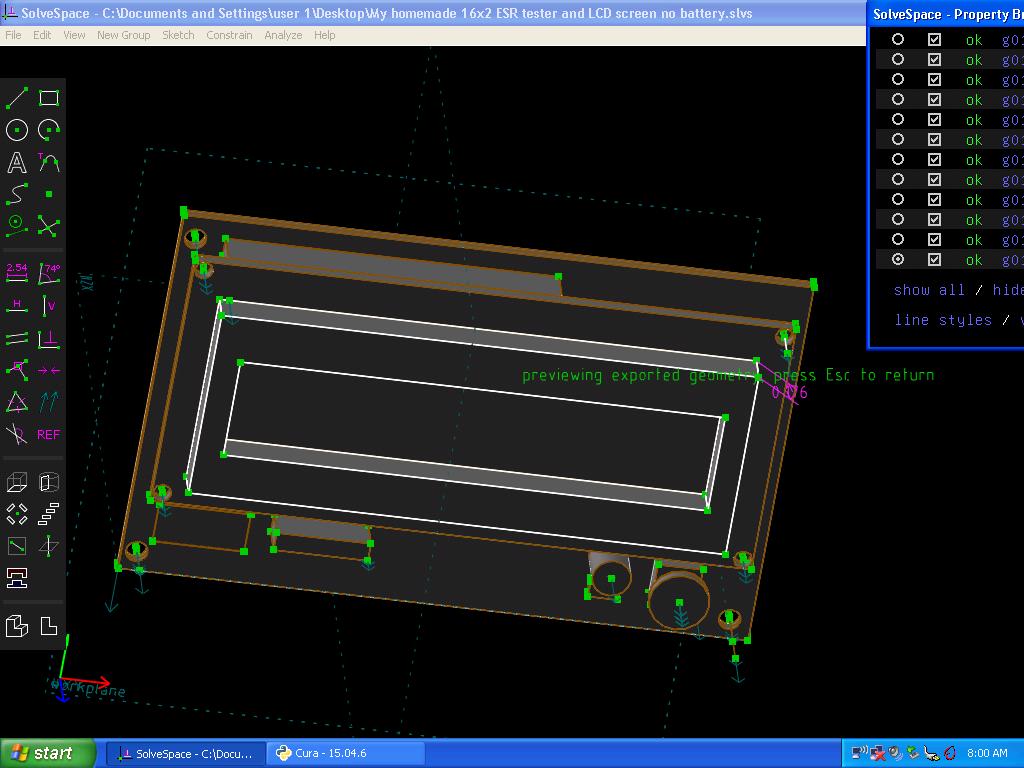
Update 1/6/18
I have worked for a long time on creating the CAD file for the case and have run into "phantom issues" with open source CAD software- chasing errors which are in the form of "redundant" constraints and having to make sure ONE and ONLY ONE constraint is a very frustrating way to use software. Sometimes scrapping a version simply because an error/bug cropped in there even though running tests on it show no errors. Nonetheless - this process is helping to make the shape and make decisions on where walls/shell parts etc for the case should go and keeping things straight and basic looking to reduce complexity that the software has trouble with.
Here is an almost fully enclosed shell (rear wall is not a wall but a battery compartment separator) full of red areas where the software is warning about trapped parts- but I plan on deleting the electronics after case is completed. In the meantime the red lines are an obstruction in viewing/creating. Decisions on where to split the case is not made yet.
Update 3/4/18
I have figured out how to solve the redlines in Solvespace for my drawing. I needed to add a checkmark on "layer" G023- extrude "Force NURBS ... triangles" which removes the redlines. These redlines were thick and heavy and I couldnt See the drawing to continue. Adding this checkmark somehow tells the drawing "Its OK to have back-to-back adjacent parts" that is the best answer I can give. There is no error and most of the time the software works fine without this. But every once in a while in my drawings - I have to figure out which "layer" needs that checkmark. I dunno - its just something to do with Solvespace- who knows? Its a good free software- what do you expect for free? Its good enough and works fine. I have added a screenshot of the checkmark added to make it work.
|
|
Caseless ESR tester red areas in Solvespace.JPG Size : 128.703 Kb Type : JPG |
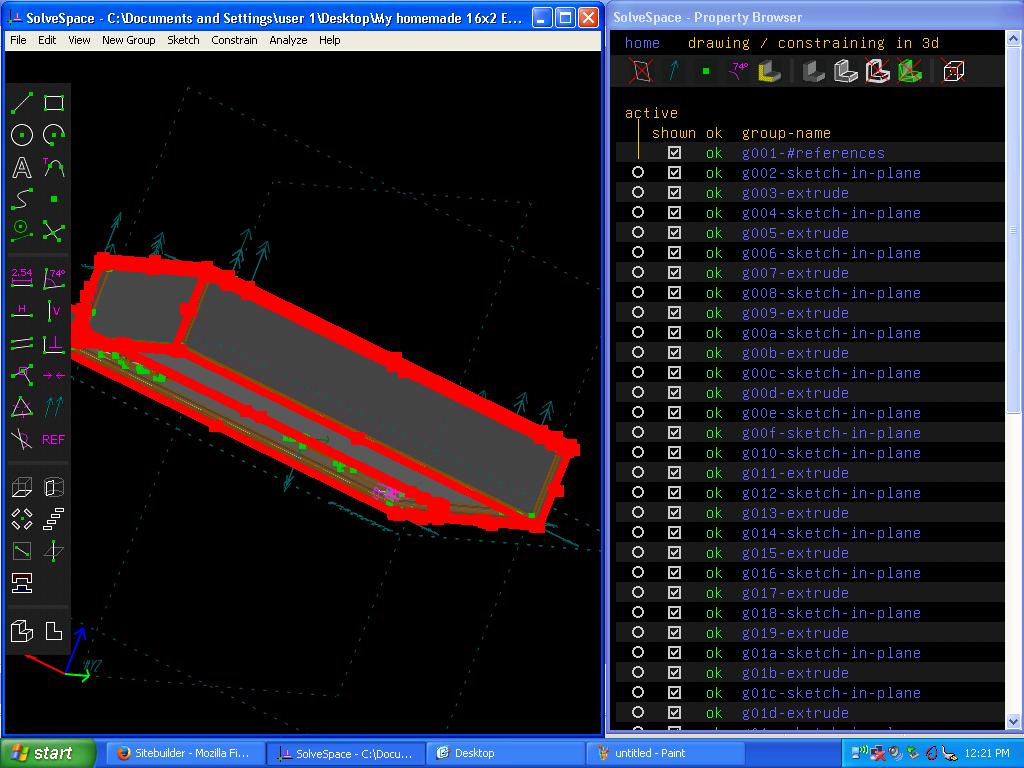
|
|
Solvespace Layer g023-extrude checkmark on FORCE NURBS to remove redlines 030418.JPG Size : 109.016 Kb Type : JPG |
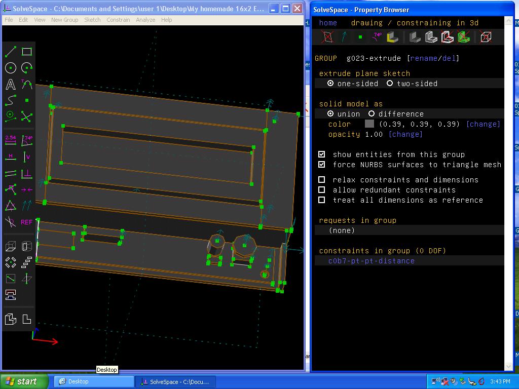
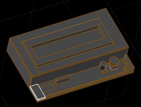
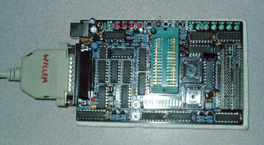
I own several versions of Willem Eprom / ROM/ Prom/ EEprom / Flash / PIC Programmers ranging from early DIY etched board to the above online-purchased advanced model. Pictured above is a PCB50 which is a digitally selected (no dip switches) pushbutton selected model. I can select the voltage and other paraameters with pushbuttons. The LED bargraph lights up according to my settings. It is exactly like the earlier models of DIY Willem and has the same functionality of my other boards - but I like the digital selection and use it/prefer it 100% over my other Willem programmers. This is a parallel port version which uses the parallel cable to communicate with a PC. I use a dedicated older PC for this Willem programmer. It is powered by the USB cable but the USB only supplies power to it. I have used this WIlem to flash/reflash BIOS and update ROMS and burn chips for use in projects. The Willem programmers are very useful - their only drawback is lack of thorough documentation. So I had to figure out each and every chip setting manually - for all chips I have ever burned. You would think that an online source for these settings would exist - but really and truly there is no source for this list.
I have an interest in compiling this list of settings as I have figured out quite a chip few settings on my own and I keep a detailed notebook on what settings worked for me for each chip model I have burned. I use Willem Pro software version 0.99kb for PCB5.5c running an older pc dedicated for chip burning which runs WinME and has both a USB and parallel port and 1GHZ processor which is sufficiently fast enough for high quality burns.
I have successfully figured out the settings for the following chips using Willem, and I have made notes for the following:
PIC12F629
SST 49LF040B
SST 49LF004B
SST 49LF002A
Winbond W39080APZ
Winbond W39V040BPZ
A29002IT-70
SST MPF 39SF020A
Winbond W49V002AP
Winbond W39V040FCPZMX29F004TQC-90
ASD AF49FZ008-12 0018
2764 older UV erased chip
Texas Instruments TMS 2732 older UV erased chip
Note
(Interestingly the 2732 and 2764 uses substantially different
settings on the WIllem 5.5C programmer - I started out
trying to use similar settings without success)
If you need the above settings - contact me to purchase these Willem settings for a few dollars each payable by paypal for the DIYer. Also available is custom re-flashing the file onto a chip that you provide. I can read existing chips, erase chips, and reflash old chips and burn new chips. Some people like to send me their chip. Some people like to do it themselves- but do not know how. I charge a small fee. If have a chip that you want settings for or custom programming - let me know, and I will quote a fee. Sorry I cant program MAME roms for you due to copyright.
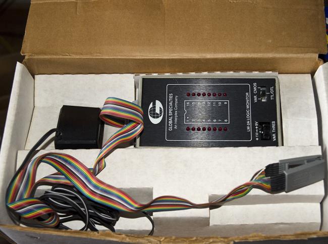
This device is basically a "Logic Probe" It comes standard with a 16-pin ribbon cable and attaches to the top of the tester with an IDC connector. The IC Clip end is a 16-pin Dual In Line ( DIL ) which can attach to many chips 16-pin or shorter. For much smaller chips and or narrower chips a self-made adapter is necessary. Imagine 16ea logic probes attached to an IC alligator clip - that is what this device is. One LED connects to each and every pin on the IC. The LED is either Full On/Medium On/ Off/blinks to show the logic state of that particular pin on the IC (also half bright means there is a waveform present). Of course the main purpose of this is to monitor a live circuit while it is under power and operating.
Sometimes a chip will have a bad pin and the rest of the IC operates. This bad pin will stand out as being in a different state when compared to previously tested boards of the same type (in reference to my notebook notes from previously tested boards) So it is important to keep a record of boards I test regularly and compare them with drawings or sketches or descriptions that I have observed.
Also this is useful for comparing 2 boards side-by-side (one known working board and one non-working board)
For example a board previously tested may say in my notebook, "IC XXXXX ... pin 6 ON" but when I test another board - I may actually observe that pin 6 is actually LED off. Then that makes me suspect that this chip has an issue (When one chip has an issue - this also affects other related ICs LED status too). Many boards have a boot-up logic state - as soon as that board is powered on - certain LEDs light. If something is not right about the light up or off sequence - it is observable with this tester. I tend to use this tester by clipping over the IC and then powering up the board under test - that way there is a predictable initial viewing of logic state of that IC in my notebook. Sometimes I will elaborate in my notes about what the chip looks like after bootup is complete or in various modes.
I like a Logic monitor (rather than a logic probe) because it is safer for the circuits and ICs - due to cliping an IC Clip over the chip - rather than probing around with a 1-pin logic probe. The IC Clip is locked in place and can be attached with the power off. So there is absolutely no reason to ever short 2 adjacent pins on an IC (by probing with a Logic Probe for example).
If the LEDs flash/ON/OFF state according to my notes (from previously tested boards) - that chip is probabably not the issue with the board or a more in-depth testing is needed on a different tester.
The IDC connector lends itself to changing out to a homemade IC Clip of any style (DIL, DIP, SOIC, etc) and there are a tremendous amount of IC chip pins and styles including surface mount that I make custom attachments/ribbon cables for my own use as I need them. Big-Auction-Site is a good source for used or new IC Clips.
One of the main purposes of this device is to see if a chip is dead or pins are dead or stuck on or stuck off. Another main purpose is to determine how much voltage a chip is rated. The variable control allows viewing the brightness of the LEDS. It is a good idea to run this device - BEFORE using an In-circuit IC tester as some boards run chips well beyond 5V. If the board is supplying more than 5v - then an in-circuit IC tester should not be used - otherwise the IC tester will be blown or damaged due to higher than 5V . Purch 9/14 approx. Mfg Date unknown estimated 1985
Sometimes Global Specialties is written as "Continental Specialties" as it apears they had a business name change. The LM-3 which I am looking for may be "Continental Specialties" or "Global Specialties" either one.
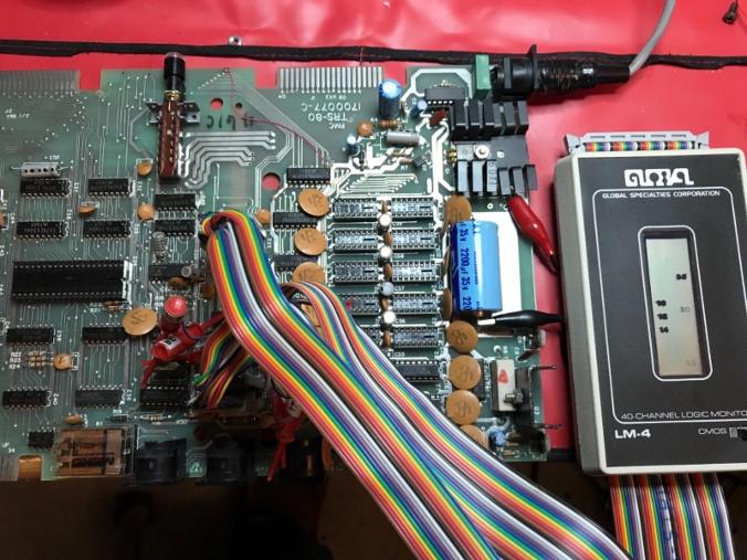
Note I also purchased a Global Specialties LM-4A 40-pin Logic Monitor from big-auction-site 8/14 but it arrived with a severely damaged LCD display which looks proprietary. If the reader has a replacement - LCD screen for it let me know. My 16-pin logic monitor uses LEDs which is more rugged. I suspect the previous owner left this LM-4 someplace where it froze and internally cracked the LCD. I dont believe it was damaged during shipping. The seller was responsive and immediately refunded without requiring return. I included a downloadable picture so can see the LCD is bleeding black liquid crystal fluid internally (actually LCD liquid is clear but the polarizing filter makes it apear black). A working LCD would have no black showing. I am still looking for a LM-4 or LM-3 made by Global Specialties as these are 40-pin capable. Ideally I'm hoping to find an any condition LM-4 with a good LCD which I can use for parts. Let me know if you have one for sale.
Note: I have purchased a second LM-4 12/13/18 (4 years later of regular onlline searches for a replacement unit) to replace the Bad LCD unit as received a long time ago. I was looking for a good unit for years and finally found a good one on big-auction-site. What is excellentabout this find is that it comes with 2 sets of cables. I already have everything for the first unit like the standard 40-pin cable and manual The second unit recently purchased comes with smaller IC clips and individual test clips. This made it very attractive to me as the ad also showed it in operation testing a TRS-80 circuit board and the display was working etc. The combination of reasonable price and extra cables was a deal clincher for me. I feel like I finally found a solution to the first unit with a bleeding display -probably from being stored the seller in a bad location where it froze and internally broke the LCD.
Update 12/22/18
I have included the sellers explanation on how to use LM-4 as a text file. I have not yet tested the LM-4 and too many customer repair projects at this date.
|
|
Global Specialties LM-2A Box.JPG Size : 53.858 Kb Type : JPG |
|
|
Global SPecialties LM-4.JPG Size : 116.405 Kb Type : JPG |
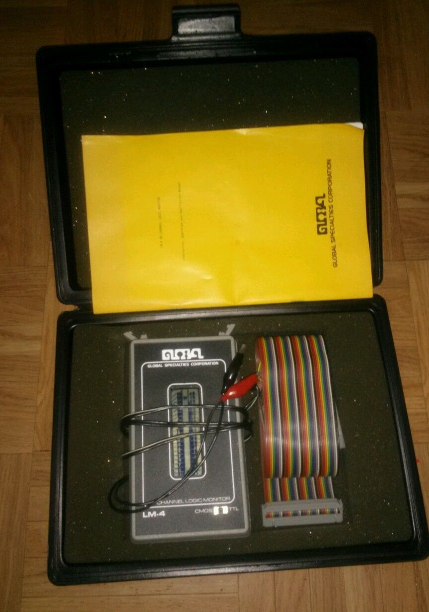
|
|
Global Specialties LM-4 Logic Monitor Pics shows TRS-80 Test 121318.zip Size : 1996.797 Kb Type : zip |
|
|
Global SPecialties LM-4 with LCD Bleeding as received.JPG Size : 375.486 Kb Type : JPG |
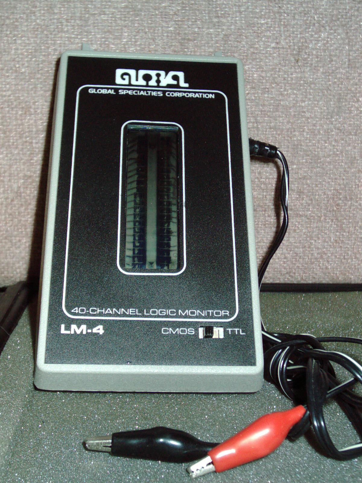
|
|
Continental Specialties LM-3 Logic Monitor Ad year 1980.JPG Size : 79.461 Kb Type : JPG |
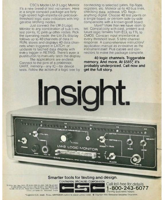
|
|
Global Speciaties Logic Monitor LM-3 Pics.zip Size : 1752.838 Kb Type : zip |
|
|
sellers explanation for how to use LM-4 122218.txt Size : 1.349 Kb Type : txt |
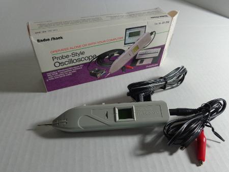
|
|
Radio Shack Probescope Backside.JPG Size : 123.053 Kb Type : JPG |
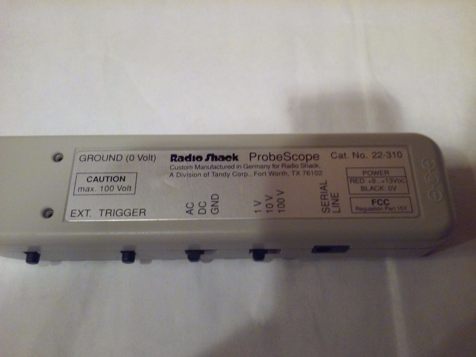
|
|
Radio Shack Probescope & Wires etc.JPG Size : 162.877 Kb Type : JPG |
I purchased this item from my local Radio Shack store in the mid 1990s. It is a portable pocket pen-style oscilloscope 5MHZ and maximum 100V measurement. I use it primarily as a logic probe as it shows TTL and Analog HIgh and Low and also live waveform.
I purchasd this brand new and at the time of purchase I barely had the funds to buy it, and I pressured myself to buy it because it was soon to be discontinued at the time. An optional accessory for it was a battery pack which clipped to the rear of the unit. I have never seen this optional accessory or any photos of it. If I had the funds - I would have special ordered it as it was not an in-store accessory. This tester runs on a 9V standard rectangle battery and has a backlight LCD.
I have read that some online people blew out their Probescope by connecting over 100V to it. The book clearly states (also says on the backside of the unit) that it is for up to 100V Maximum - do not attempt to measure your power line with it. DO not accidently connect it to power supplies etc. I suggest only using it for analog / TTL low power testing - using it as a high-end fancy Logic Probe.
It has a graphic pixel display which shows live moving waveforms and also gives a numeric display for voltages. The buttons are momentary and used to toggle between modes
I loaded the software diskette that was included - on my Toshiba 1910 B&W laptop with Windows 3.1 (laptop purchased new in early 1996) and is useful for making snapshots or printouts of the waveform. It includes a cable to connect the Probescope to the 9-pin RS232 port. I have this old perfect condition laptop for running old software and printout is to a Panasonic KXP-4420 B&W 300dpi laserprinter or Canon BJC-70 300dpi inkjet color printer or screen capture imported to Adobe Photoshop or Aldus Photostyler - from there I can export it to my modern computer and color laserprinter Samsung CLP-300 600dpi.
This pen style oscilloscope has no X-Y mode and cannot be used with my Lissajous pattern tester - because that requires an oscilloscope with XY mode for drawing. I noticed that there are a few modern mini-oscilloscopes on big-auction site - but even those lack an X-Y mode. X-Y mode is very important to component testing add-ons which this Probescope cannot attach to. A worthwhile homemade attachment is a 1x or 10x probe - I have never made one/modified one because I purchased a full size used oscilloscope Kikusui a short time later after purchasing this pen-style unit.
If the reader has a "special order" 9v battery pack available for sale - I would like to buy it. When I someday buy or build a 3d-printer - a worthwhile project is a clip-on battery pack for it. I have never seen one - no pictures of it were posted in the Radio Shack catalog.
Note there is a "Sister" unit made by "OziFox" approx the same era and was virtually identical except internally there were some minor differences between these two brands. The main difference is a much wider 2x "rectangle" display on the Ozifox as the Probescope has a small "Square" 1/2 wide display. Otherwise they look nearly identical.
Here is a youtube video (not my video) showing Ozifox unit display
https://www.youtube.com/watch?v=GritUZ86gN4
Update 4/24/17
I emailed the mfg and inquired about the availability of a Radio Shack special order battery pack for Probescope which I bought brand new in approx 1990. The response I got is that he will check with someone and get back to me. I never got a response (about a month and a half ago) and no reply to several attempts afterwards. I had inquired about obtaining a photo of this battery pack, any parts or pieces, or to buy the battery pack in any condition. I didnt receive any information or photo or anything. I got a reply but that reply supplied me with nothing.
Can anyone provide any information about this special order battery pack? Anyone ever order one? Any photos of it? Any still in existence? Any insights would be appreciated.
Did the battery pack attach to the Probescope as a clip-on or was the whole case replaced and battery inside longer or wider case? Was it rechargeable or run on standard 9V or AA or AAA batteries? Was it just a module "brick" with a cable that plugged into the back of probescope. I have no idea what it looked like. I know of no-one else who ordered this battery pack. Let me know.
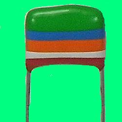
Odd looking Capacitors with Color Stripes
Sometimes I run into strange looking parts as Im repairing older devices. For example, while fixing a 2200watt Gasoline powered Generator Alternator from the 1970s - I rebuilt the foam sealed aluminum encased Generac Electronic Control Module (new one is unobtainium- so I decided to rebuild it) and saw 2ea rainbow colored disc "capacitors" which I saw were broken/busted due to vibration (and possibly from prying off and coaxing off all of the foam it was encased in). My BK Precision meter showed them as capacitors - as I tested the caps with one missing leg - still worked but needed replace. On big-auction-site there are some sellers who have photos of these vintage capacitors with various color stripes which denote the capacitor values. Some guitar mfgs and amplifier mfgs etc used them and some repair techs feel they are better for certain applications - such as music studio reproduction and musical instruments etc.
I am including here a photo of one capacitor and a summary of what the color band / stripes mean. Generally these are considered Polyester Metal Film capacitors and the "Tropical Fish" capacitors inside my vintage Craftsman generator were quite brittle and were replaced due to cracked busted outer shell and dangling leg. Replaced with standard polyester film capacitor of same specification (if it were a musical application it would be better to replace with a tropical fish capacitor to avoid sound reproduction accuracy gripes/complaints. For a generator - a standard modern epoxy encased capacitor is fine and would better withstand the engine vibration - in my professional opinion. The old one lasted 40 years (bought it used- who knows how many owners) which is not too shabby. If I didnt rebuild the electronics board - then this old generator would probably go into a landfill or recycled. It works fine now.
Color Code
0=Black
1=Brown
2=Red
3=Orange
4=Yellow
5=Green
6=Blue
7=Violet
8=Grey/Gray
9=White
Tolerance Color Code
Black=20%
White=10%
Voltage Color Code
Blue=600V
Yellow=400V
Red=250V
Brown=100V
Color Stripe Meaning
Cap color is Digit1
Upper Stripe is Digit2
Next stripe down is # of zeros
Stripe just above base is Tolerance
Base color is
"Tropical Fish" (a slang electronics technician word) vintage Bullard capacitors are generally but not always picofarad pF small value caps.
My Test Notes on ODD parts
Blue non-directional Diode TIP DB3 is used along with TRIAC When testing a blown DB3 showed as 26pf to 28pf on caseless component tester. And when I bought a replacement exact match - the brand new one showed as "no component or unknown component." very easy to mistake a good part as being "open/blown" In this case I changed it out with the new one.
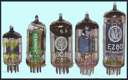
Vacuum Tube Testablility For U-Test-M Tube Tester
I am making a list of testable tubes here. This list is not necessarily about cross referencing. This list is about what settings to use for the U-Test-M Tube tester - as there are more tubes in existence than are listed on its rolling chart. So this Testability tube list will allow me to take unlisted tubes and know which "known tube" it is tested the same as on the U-Test-M roll chart.
I hope I explained that clear enough - this is not a substitution chart for you to swap tubes in your TV set or Radio. This is a chart which expands the capabilities of the U-Test-M tester. I need to look up your tube on my list and then find an underlined tube heading - then use that "subtitute tube number" to look up the setting in the roll chart. It is an in-direct method of expanding by many times the capabilties of the U-Test-M.
The U-Test-M is regarded as the pickiest of all of the testers- people regular folks who repair their own TVs and Repairmen often say - "when I test that tube on my Hickock it passes just fine - but on the U-test-M - it fails it. That XXXX drugstore/tv repair shop just want to cash in on selling tubes. Dang-nabbit (or worse)" Well I look at it this way - The U-Test-M is for people who want to restore a tv or radio to top notch condition - rather than "good enough". Still it doesnt test Mutual Conductace - so really having more than one tube tester is a good idea. I plan on owning a HIckock and a U-Test-M - Both (I dont own any tube tester at this time). There isnt any reason why a shop should only have one tester. If the tube passes all the tests from every tester - then that tube is very good. If the tube is very good - it should be able to pass even the U-Test-M. I'm still looking for a U-Test-M model 2500 I havent purchased one yet- they are usually sold by sellers several states away and I'm hoping to find one that is within driving distance. Let me know if you have one for sale.
With tube based electronics - the weakest point is not the tube - it is the paper and wax capacitors - that is the souce of most problems. The tube is easy enough to se if the filament is glowing or not. Just becaus the filament is glowing - doesnt mean the tube is good. With the invention of the ESR meter - testing those old caps/replacing a few bad ones is a breaze and usually enough to get an old set up and running. But the U-Test-M made testing tubes easy enough for the Do-It-Yourselfer and I remember a local Zayre store (you dont hear that store name too often anymore) had a U-Test-M model 2500 at the front of the department store just in front of the cash registors and to the right of the Service desk. I can remember testing tubes at the Zayre store (as a customer using the stores self-serve vacuum tube testing machine in the middle 1970s approx) The Zayre store was a department store like Kmart, Target, Walmart, Venture etc.
It will take quite a while to make this list and may contain errors so use this on an at-your-own-risk basis - as I will do my best. I am using a multi-column feature and this is something that is new for me when building my webpage - under construction - your patience is appreciated. This section Commenced 1/25/14
Column1
01A 12A, 112A
0A3 0A3A, VR75
0A3A 0A3, VR75
0B3 OB3A, VR90
0C3 0C3A, VR105
0C3A 0C3, VR105
0D3 0D3A, VR150
0D3A 0D3, VR150
0Y4 0Y4G
0Y4G 0Y4
0Z4 0Z4A
0Z4A 0Z4, 0Z4G
0Z4G 0Z4, 0Z4A
1A4 1A4P, 1A4T, 1B4, 1B4G, 1B4P, 1B4T, 951, 32, 34, 1C4, 1K4
1A4P 1A4, 1A4T, 1B4P, 1B4T, 951, 32, 34, 1C4, 1K4
1A4T 1A4, 1A4P, 1B4, 1B4G, 1B4P, 1B4T, 951, 32, 34, 1C4, 1K4
1A5G 1A5GT, 1A5GT/G, 1T5GT
1A5GT 1A5G, 1A5GT/G, 1T5GT
1A6 1C6
1A7G 1A7GT, 1B7G, GT , 1A7GT/G, 1B7GT/G
1A7GT 1A7G, 1B7G, GT , 1A7GT/G, 1B7GT/G
1A7GT/G 1A7G, GT, 1B7G, 1B7GT, 1B7GT/G
1AB6 1AC6
Column2
Column3
Column4
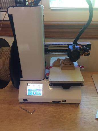
Alunar HB-R100 3D Printer
I purchased
this used from big-auction-site in very good physical condition with
original box September 2016.100mm x 100mm x 100mm build volume. Standard Non-heated bed for
PLA only. 1.75mm filament. I see that the mainboard is Chitu - so I decided to upgrade it
to heated bed and ABS capable. I like the 2.8" color touchscreen
display and the sturdy thick steel construction. The standard use of a common reprap
nozzle/heated tip system, spool feed system, ALL 5ea standard identical Nema 17 stepping
motors makes repair and upgrades possible with common reprap components.
The purchase of this 3-D printer is driven by my need to make cases/parts for several testers- which the vendors sell without a case.
I ordered a WIFI module and Heated Bed module as Add-ons for Chitu mainboard. I ordered a standard 360watt 12V power supply typical for DIY 3d printers (I spent a whole day fixing this $20 brand new aftermarket power supply- unsoldered torroid transformer, straightened bent heatsink, retap threaded holes, bent aluminum case, etc). The standard power supply which came with the Alunar HB-R100 is not powerful enough to drive a heated bed- hence the need for the add-on module and add-on power supply.
***********The following paragraph has INCORRECT conclusion about cause/solution***********************
***************************************************************************************************************************************
Update 11/27/16
I am adding this tidbit of information as in retrospect- The entire previous paragraph insights about crazy BRRR homing function was incorrect or partially incorrect?. See Just yesterday I installed the MOS module/standoffs/drilled 4 holes in the case. After doing this modification - with no electrical connections - just mounting work - I put it all back together to make sure nothing was broken and screen uncracked. Well I got the not-homing-correctly (but no BrrrBrr noises) - very similar to when I originally got the machine from big-auction-seller. So I though about - whats going on here? Well the only thing that I did really is I moved a zip-tied bundle of wires out of the way. So I figured - well maybe some connector is unseated or a wire internally is busted or making a bad connection. So I took the bottom off and moved that zip-tied set of wires to where it was before and also pushed down on all of the connectors to make sure it was seated correctly. When I reassembled - homing function worked just fine. So in retrospect, maybe it wasnt a firmware issue - but instead was some bad connection which I reseated to make proper connection.
*****************************************************************************************
This 3d printer is very similar Looking to MonoPrice Select Mini / Malyan M200 but not the same at all (steel case is different (side of case has panels held w/ screws versus welded all sides case, z-axis stepping motor (all 5 stepping motors are identical nema 17 style on Alunar) LCD Touchscreen, Chitu controller, non-heated bed platform standard- but upgradable) The Monoprice and Malyan use a rotary knob selector and non-touchscreen color. Different controller and firmware. The X-Axis and overall apearance looks identical to Alunar & Infitary ??????
Sister model - which look very similar and may be exactly alike? Infitary HB-R100 (alibaba auction site)
My Installed Upgrades DIY
(360watt PS, Chitu WIFI Module, Chitu Heated Bed PCB, Firmware from SD card, Heated Bed MK2B (special size 120mm x 120mm) Cura software 15.04.6 runs on a Win XP SP2 laptop Dell 3650
Equipment which I need a case/other parts for
1. Electronic Component Tester (Transistor Tester/LCR/ESR) case
2. Willem Programmer case (I have several version boards)
3. Caseless IC Tester case (numeric keypad style)
4. Caseless IC Tester case (row of keys style)
5. Power Button/head for BoardWalker 103 to fit power switch shaft
6. Side Cover for BK 560 IC tester (combination of 3d printed parts and ABS textured sheet cutouts)
7. 9V Battery Pack Add-on Attachment for RS Probescope
Update 1/21/17
8. Switch hole cover for GJ8018LCD Hot Air solder/desolder tool - done
The main purpose for this 3-d Printer is to make the above cases/parts. I want to use ABS (ABS Styrene) rather than PLA as PLA is organic. I want to make parts from ABS filament and my initial tests with ABS curling in random layers during the print leads me to believe that a heated bed is necessary. I was able to get ABS to bond to a 1/16" textured ABS black sheet without hotbed but subsequent layers randomly didnt stick well to the underlying layer- in thin walled or thin sections. A test cube shows warped bottom but the rest printed fine. For my needs in printing ABS to make replacement parts / cases / cover etc ABS is my choice for a professional project completion.
My initial test with this 3d printer was astonishment - the very fine detail and exact placement of one layer over the next layer. Capable of "Layers Almost As fine as a record groove." Also I find that Cura software reads my 3-d Scanner DXF/STL files from my 2ea RolandDG Picza scanners (which lightly contact an objects surface with a needle tip)
After firmware install - all functions work properly -
without any more BRRRbbbRRRRR or wrong direction axis movement. Bed leveling procedure works well. Nozzle touches the bed off-to-the-side momentarily to remove "snot" or dripping before beginning a print. The extruder nozzle makes a circumference path just outside the part- during this circumference pass - the filament line attempts to cling to the printbed and is eventually successful - either right away or at some point around the circumference path.
I find that smooshing down the initial layer onto the ABS homemade sheet really attaches very well onto a non-heated standard bed (by having a level bed and leaving only a 1 piece of paper gap between printhead nozzle and bed while leveling). BUT subsequent layers 4-5-6+ layers up there is a pealing or curling up - so the homemade ABS buildplate I made only helps the initial layer - the heatbed heat is required to continue to heat previous layers. Otherwise it will curl up - similar to the way a bi-metal spring inside a conventional thermostat for a home furnace works.
Cura Software Printout Specifications
.1mm Layer height, 230deg C extrude Temp (for $10 ABS Black Filament) , Speed 30 to 40, 1st layer speed 20, Last layer speed 20. Downloaded from the Cura website and this version works with Windows XP SP2 just fine.
I save the g_code file to a standard 2GB SD card and then take the card to the 3d printer and run the 3d printer standalone- without a laptop attached. The laptop is used to run Cura to import drawing file (.STL) then save as G-Code onto the SD card. While the 3d printer is making the part - the settings such as speed and temp can be tweaked from within the Alunar LCD screen.
Heated Bed Notes
I contacted MonoPrice by email and received a reply that "Unfortunately we do not have any replacement heated bed available for sale at this time" 9/28/16
I contacted Malyan by email and received no reply regarding buying a heated bed from them. 9/27/16
I considered using a heated bed option for Fabrikator Mini which measures 120mm x 120mm - some of these add-on boards have 15W or 60W connectors for low power or higher power. In the end I decided to use a different one because the way the predrilled holes placement.
The MK2B special size 120mm x 120mm holes placement lends itself to "hug around" the existing aluminum plate on my Alunar HB-R100 using DIY metal plate clips or bands
Update 10/16/16 I emailed big-auction-site seller of my MK2B Heated Bed - question - to find out screw thread size. Answer M3
Update 10/22/16
I positioned the heated bed MK2B 120mm x 120mm such that the printhead can reach all areas of the heated bed. Then I used a magic marker to mark the 4 points where the heated bed's threaded screws touch the existing aluminum bed. I used a Dremel model 395 with a brown cutting disc to eat away the edge at those 4 marked points. I carefully used the Dremel tool to make a clean C shaped notch and cleaned up my work even smooyther with a 1/8" diamond encrusted bit. The result is 4 smoothly cut C shaped notches. The heated bed is able to mate up with the existing aluminum bed - just a tad above it. I ordered 8ea (4 extra ones not needed) for about $3 M3 Knurled Thumb Nut so I can secure the heated bed. I am awaitng the arrival for these nuts. The rest of the items have arrived - some from USA and some from international. I have included a photo of these mini M3 thread thumb nuts and my DIY notched modded aluminum plate.
It is important to note that any type of pressure will BEND the aluminum plate - so no drilling or using a punch!!!! I Carefully clamped the aluminum plate in a small vise with cardboard to protect the finish. I clamped the aluminum plate vertically and used my marker marks as a guide and made test fits with the heated bed to check my progress. I was careful never to put force on it and I believe it is nice an straight.
The notches are beyond the extruder tip reach and the notches will never interfere with any non-heated bed print. I have included a photo of the notches and heated printbed add-on modification.
As a result of the add-ed heated bed mod- I had to readjust the Z-axis switch thumbscrews so the print nozzle is just above the heated build plate rather than the now-notched aluminum plate. I found that there was enough built-in adjustability of the z-axis thumbscrews to accomplish this.
WIFI
I have installed the WIFI module and can connect to it using an Android TV box but I lack the app to control it. I see the Alunar's LCD screen shows 0.0.0.0 and WIFI checkmarked. I still need to figure out how this works. I feel that the WIFI module is working properly and is installed properly. I see an online page which shows an app for Apple phone but I dont own that brand at this time. I may need to acquire an Apple brand tablet or phone in order to use the WIFI control app.
Update 10/24/16
I was able to connect and use my WIFI add-on module. While I searched on the Chitu website a week ago , I downloaded all of the files and folders related to my mainboard, power module, wifi module etc. I have been reading and studying the PDF files and trying to figure it out. I previously had an unsuccessful attempt to load the software ChiTo Pro last week. But today I decided to try it again. It worked fine today and after installation I received no error. I disconnected from my internet WIFI connection. Then I connected to the Chitu WIFI module which shows up as "3d Printer" WIFI signal with 5 bars of power since it is so close. I have been trying to figure out how to connect and what seems to work is double clicking on the picture of the green chain in upper left portion of Chitu pro screen.
Here is the download link to Chitu Pro Software (works on my older laptop with XP)
http://cbd-3d.com/forum/viewtopic.php?f=9&t=86
The odd thing is that I tried to install it last week and after installation gave me an error. The ONLY thing I did with my laptop since last week is - I tried to install Microsoft Net Framework on it where some other software required it? That may have added some file to my system that it didnt have before?
I am able to see the content of my SD card, home works, some commands I tried and my 3d printer moves. Right now I dont know the Gcodes but from my experiments (very carefully) seems to work. I tried to disconnect/reconnect/close program/rerun program and seems to be repeatable. Although sometimes screen is mostly English and other time has international language characters. But that is very minor - I can still figure it out regardless of language characters.
Im so glad the WIFI works now. I need to calibrate my 3d Printer and having access to those commands is now possible.
I figured out how to change ChiTU Pro software to English - in upper right hand corner there is a question mark symbol - just to the left of that is a graphic symbol - clicking on the graphic symbol will toggle between languages (required restart of Chitu Pro)
I issued some command M503 (to list current settings in the 3D Printer) doesnt work but responds "OK"
From what I was able to read about most 3d printers - this should have listed all of the internal settings - but didnt work for me.
In Cura I can scale an object so what I need to do to size the object correctly is scale up a certain percentage to get it to be the right size. Right now my "steps per mm" is probably wrong and I dont know how to list the internal settings or change them. So scaling the object in Cura is the present solution. I was hoping to use Gcodes and Mcodes to fix this.
After my succes on my PC laptop, I tried again on my Android TV and was able to get the APK file downloaded to a flashdrive using a PC and then installed on the Android TV using the built-in "App Installer" then loading the Chitu app file from my flashdrive.
Here is the link for Android version of Chitu controller which worked for my TV and probably any Android Device.
http://cbd-3d.com/forum/viewtopic.php?f=9&t=28
I can say that it is a much more basic control than the Pro version but I tested it to home and move and seems to respond like it should. Im glad Android is now working as a backup to my PC- just in case my older laptop fails.
Update 10/28/16
I switched the wires around at the connector of the MK2B special size 120cm heated bed.
-Heat = Black
+12V=Red
SIG=White
5V=Red
GND=Black
The above colors seem to make more sense than the random colors as received. I used a watchmakers screwdriver flat to press the clip-in portion of the connector and then just remove the wire with crimp end and re-insert where it should go.
I have determined that this heated bed does come with a thermister as I put my finger on the very center SMD component (the one closest to the center hole) and resistance changed with my body temperature. I also compared the reading of the SMD component to a pack of 10ea replacement thermistors I purchased on big-auction-site. The resistance value is within a decimal point in ohms (. I did notice that the SMD part takes a few seconds to get to its resistance value. Versus the 2-pin component responds instantly. They may work equally - but my opinion is the 2-pin version is better and faster response.
Unmounted "3950 Thermistor" Readings with a multimeter
(Room Temp resistance = 113k ohm approx My Finger Resting on it resistance = 83k ohm approx)
I get very similar results with SMD chip thermister and 2-pin component thermistor.
I have determined that SIG (I changed it to a white wire) and GND (I changed it to a black wire) are the 2 that need to be connected to a 2-pin female connector. I ordered a few online today in the form of a cable 20cm length - with same connectors on each end. The connector is called "XH2.54" on big-auction-site and on aliexpress it is called "XH connector 2.5mm" and is the same connector that was included by the mfg as part of the Chitu Mosfet board. So I just ordered a few more as I want to do a nice neat clean job.
I also ordered a green power connector from aliexpress.com "HT5.08 2pin Terminal plug type 300v 10A 5.08mm pitch connector pcb screw" which mates with the Chitu onboard socket. It is a right angle connector - not a straight one.
I am awaiting some parts to arrive from International. Some have arrived and may be anywhere from a week to a month. I like this 3d printer and to me it is worth the money to upgrade it to heated bed and wireless.
Update 10/29/16
I went to the local dollar store called "Dollar Tree" and was looking for cell phone glass screen protector - but only found plastic ones there. I found a white 5ft length Wiring Cover which is for my heat bed cables. This is sometimes call "wire loom" in automotive stores. I have never seen a whte one before and price was $1 is a good match for 3d Printer color. Resembles a mini vacuum cleaner hose with a slit down the entire length so you can stuff wires in there for neatness and less wire damage that way.
Update 11/9/16
I have received the thumb nuts M3 and they are a perfect fit with sufficient clearance where it doesnt hit the Y-Axis home switch circuit board solder joints. I was very glad it threaded perfectly into the screws on the Mendel 120cmx120cm special size MK2B Heated Bed -which secures it to my modified existing aluminum bed.
Update 11/13/16
I received the wires and connectors and I received the wrong size - it doesnt fit, but the wire color is exactly the same as the originals on Alunar 3d Printer. The XH 254 connector is too small and pins too close together and doesnt fit the Chitu socket. I will have to try again.
Update 11/14/16
I received a reply from kind seller on big-auction-site regarding Chitu MOS PCB module - the reply received was HX2.54 connector - which I believe is a Typographical error. I have proceeded to purchase XH2.54 connctors from 2 vendors on big auction site- one vendor with just the connector and a different vendor with connector with red/black wires already attached to connector. After I receive - I can just attach the bare connector to the other end of the premade-connector-with-wire in order to make a double ended cable.
I have concluded that the white wire double ended premade wire is being sold on big-auction-site as a BOGUS and is not actually XH2.54 at all. I have included the vendor reply and photos of my connectors 2nd try purchases below.
The correct connector has red/black wires and is sometimes called "XH2.54 Power connector" and the ones with white wires are too small and wont fit the Chitu PCBs. I believe the XH2.54 Power connectors are common Radio Control items and probably could be purchased from a R/C Radio Control hobby shop - but much more expensive there per piece. I prefer to mail order from international as I get a greater quantity for a few bucks. Then I have some extras for future projects.
I could also cut off the connectors on the white wire sets and just crimp on the right connects (when they arrive) to make a color matched to original wiring. Im most likely going to do that as a I have a professional hand crimper which will attach the terminals to the wire end.
Update 11/26/16
A couple of days ago I received the XH2.54 connectors with attached red/black wires and also the green HT5.08 terminal connectors.
I wrote 2ea scripts for the heatbed (created in Windows Notepad and saved as a standard non-fancy *.txt file). This updates the built-in firmware settings. "Enable Heatbed Parameters..." turns on the mainboard settings to run a heated bed. If a heatbed is NOT connected - then instead use the "Disable Heatbed Parameters..." I just figured this out and ran it on my own Alunar HB-R100 and seems to run in the menu- as I can now access temp settings which before were disabled as factory stock.
The rest of the firmware paramenters are left alone. The script only modifies the heatbed settings. I have included the 2ea scripts here.
How to load and run the script
1. Load the files onto SD card
2. Use Alunar HB-R100 touch screen to go to "Print"
3. Select the file from the SD Card
4. Print the script file- when complete - it will show that screen has been run.
Another thing I did is drill 4ea holes in the back of my steel case and used 4ea metal standoffs with screws purchased from RadioShack Cat#276-195 which I had in inventory for years. Glad I found a use for them. If I were to purchase a new set today I would look for slightly shorter standoffs - but works fine for this application - good enough.As I marked 4ea dots on my case with a magic marker, I realized how difficult it was to drill the steel- the drill bit kept running off and caused a few scratches back there from runaway drill bit. I was balancing the front of the case on a folded pair of bluejeans and resting the Z-axis on a small styrofoam block. I was very careful not to damage the screen. I also taped a piece of paper inside where I was drilling - making a paper pocket to catch steel shavings while drilling. Utimately what worked for me was to use a Dremel 395 with a fine tip diamond embedded point to make an indentation dot where the stndard drill w/drill bit wouldnt wander off. A nail and hammer would also make that quite easily BUT WOULD DAMAGE THE mainboard and LCD - DONT DO THAT. The Dremel did it safely and without bending or warping from hammering.
I found a nice out of the way- unobstructed place to mount the MOS board and other than a couple of scratches from a wandering drillbit - it turned out perfect. (see attached photos) The most important things are 1. No metal chips to cause electrical shorts 2. No damage to LCD screen. A couple of scratches are no-big-deal but could have been avoided if I used a diamond bit on my Dremel originally - oh well ... live and learn. Also the holes were deburred with a hand deburring tool - to remove any sharp edges or fragments leftover from drilling- with a chunky fat drillbit looking handtool that I purchased online years ago.
Update 12/1/16
I received the 20ea XH2.54 2-pin white connector male/female with metal crimp on terminals.
Update 12/4/16
For about a month, I have been incorrectly under the impression that my 3d printer is the cause of of incorrectly sized g-code files. But today I have noticed a glitch within Cura 15.04.6 in which it in intermittantly scales the object incorrectly. After playing with it I kinda see that after loading a file and simply opining the scale icon and clicking on the several lines without changing anything- that the rendered object chnges size. SO all this time I printed the 25mm calibration cube and it actually printed 12.5mm- that was Cura's fault - because today I printed several actual size objects - by playing with this size glitch intermittant- and I can get it to make a genuine file that prints the correct size.
Im glad to see my printouts are the correct size. I WAS simply going to scale them - but when I scaled them - by the factor they were too small - then they were too big. That didnt make any sense - thats when I went looking for a glitch and found it - in 15.04.6 which is probably the last version for Windows XP?
So I have loaded both 15.04.6 and 15.04.2 on my system and see what works for me and my 3d printer. I know 15.04.6 has the sizing issue. I hope the lder version does not- as I played with it - the older version seems to not have that glitch.
Alunar LCD "fan 0 to 100% setting for "board fan" controls the fan on the extruder. This fan is on when I turn on the machine and also when the extruder is trying to heat up. This looks odd to me and Im wondering if the board fan port is connected to the wrong fan? I think the extruder fan should be connected to "E1 or E2 fan" I havent changed anything - this is a hunch at this point. I also noticed that my extruder was wiggling during the print and affecting the alignment. So I iscrewed removed the fan shroud and plastic fan. The design of the hotend and shroud is much different than Monoprice Select Mini. Mine has a light brown tan middle and a square hotend head- I screwed the square hotend head onto the ceramic? middle by twisting as it had a thread. So somehow the square hotend head was unthreaded? I reassembled and seems to be secured better now with no wiggle.
|
|
Printbed notches and Heated Bed add-on 102216.JPG Size : 820.205 Kb Type : JPG |
|
|
Mk2B Heated Bed Special Size 120mm.jpg Size : 17.026 Kb Type : jpg |
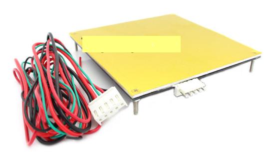
|
|
M3 Screw Size for MK2B 120mmx120mm.txt Size : 0.486 Kb Type : txt |
|
|
M3 Thumb SCrew Nut 8ea.jpg Size : 18.232 Kb Type : jpg |
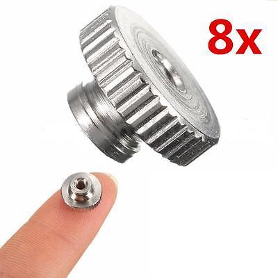
|
|
360W 12v Power Supply.jpg Size : 77.377 Kb Type : jpg |
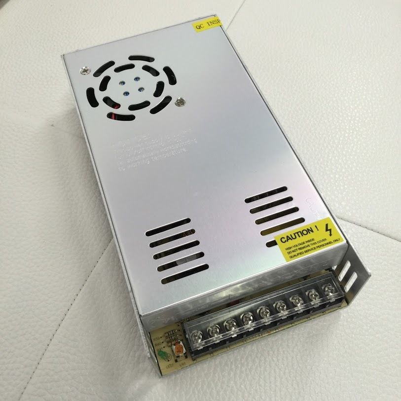
|
|
Chitu Add-on Power Heated Bed Expansion Module.JPG Size : 20.485 Kb Type : JPG |
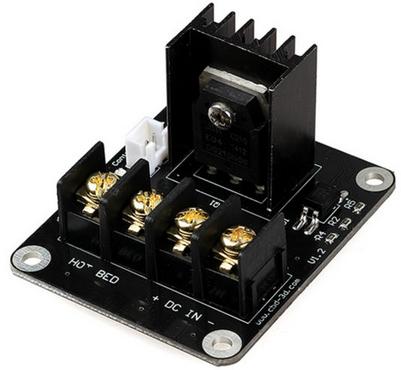
|
|
Chitu Mainboard Controller.jpg Size : 118.38 Kb Type : jpg |
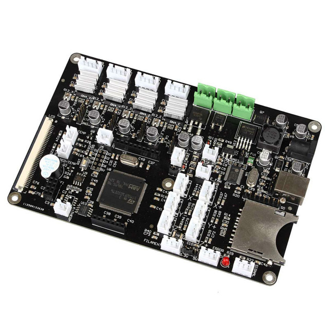
|
|
add-on Chitu WiFi.JPG Size : 16.772 Kb Type : JPG |
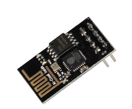
|
|
Chitu WiFi Install.JPG Size : 59.252 Kb Type : JPG |
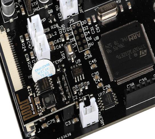
|
|
ChiTu Pro V2_0_2 connected to wifi oct2416 red arrows.JPG Size : 118.908 Kb Type : JPG |
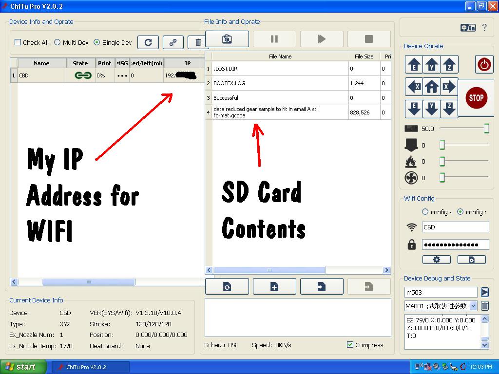
|
|
HT5_08 Terminal Connector.jpg Size : 71.906 Kb Type : jpg |
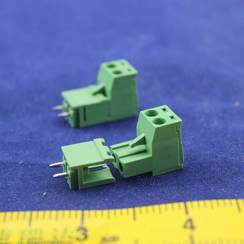
|
|
XH2_54 Wire 20cm.jpg Size : 22.215 Kb Type : jpg |
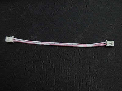
|
|
100k OHM Thermistor 3950.jpg Size : 20.858 Kb Type : jpg |
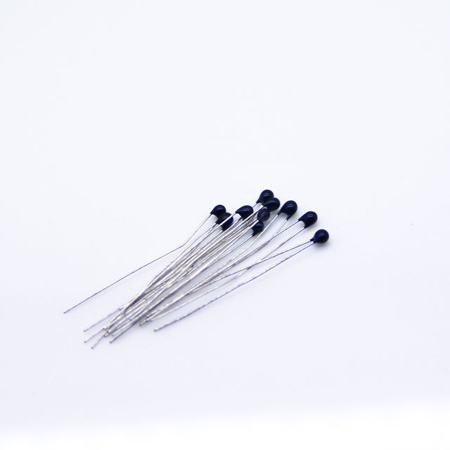
|
|
102816 White Dollar Tree Store Wire Cover.JPG Size : 766.517 Kb Type : JPG |
|
|
xh2_54 with red black wires and male female.jpg Size : 197.644 Kb Type : jpg |
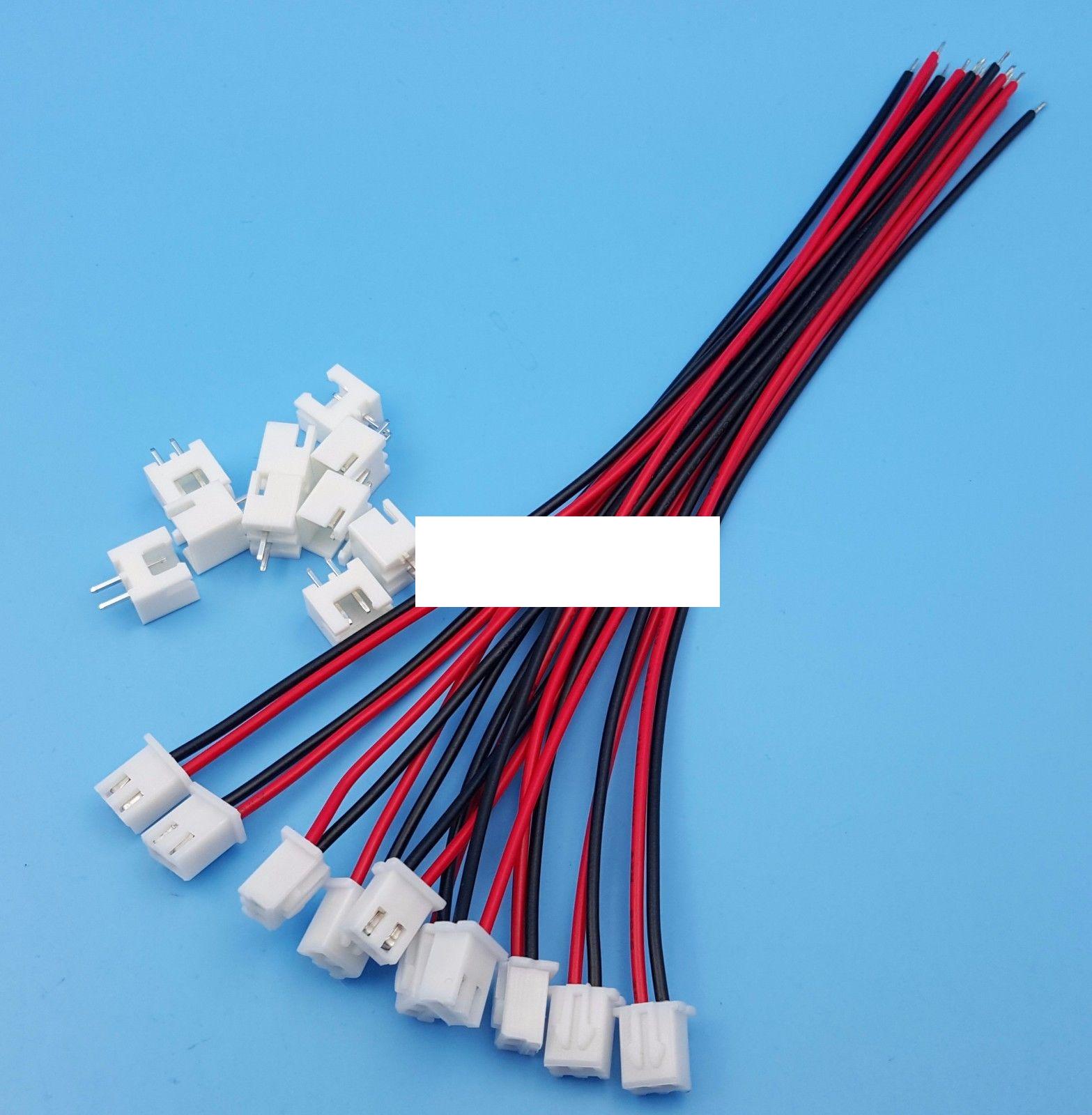
|
|
XH2_54-2P Right Angle.jpg Size : 70.182 Kb Type : jpg |
|
|
Chitu 2-pin Connector XH 2_54.txt Size : 0.648 Kb Type : txt |
|
|
Enable Heatbed Parameters for Alunar HB-R100.txt Size : 0.271 Kb Type : txt |
|
|
Disable Heatbed Parameters for Alunar HB-R100.txt Size : 0.084 Kb Type : txt |
|
|
Radio Shack Standoffs 4-pack 276-195.JPG Size : 797.183 Kb Type : JPG |
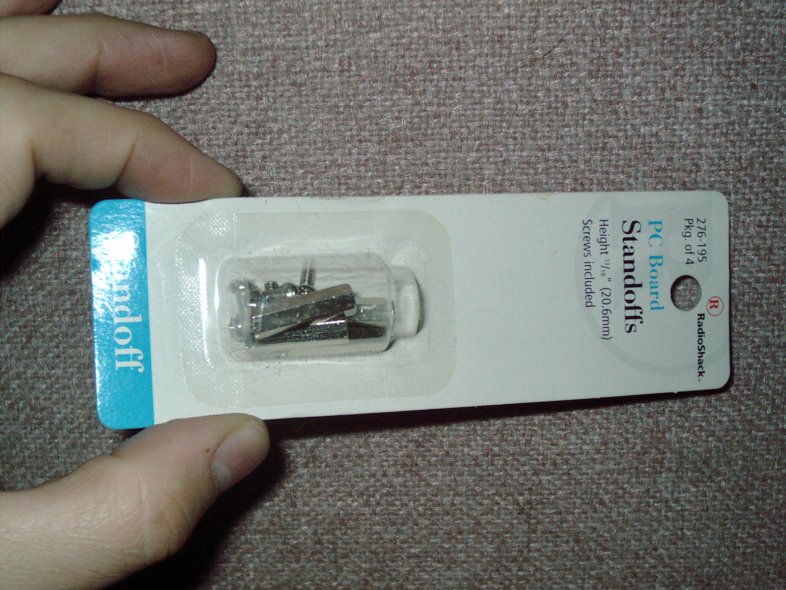
|
|
Alunar HB-R100 drilled 4 rear holes and standoffs and MOS board installed.JPG Size : 903.183 Kb Type : JPG |
I have been experiementing with printing ABS onto Egg Carton flat sheet. When I buy a dozen eggs - I save the foam carton top- which I can make 2ea small square flat sheets. These sheets make a good surface for the 3d printer to adhere ABS to. Since I have not yet completed my heated bed upgrade yet. I find that the factory stock printer can print directly onto egg carton foam. The hot end slices through this foam - as if it wasnt there. By printing a raft, the abs object then seems to be fully formed. I have made a few test prints of miniature objects printed on the foam sheet and supported by a raft.
Also very recently I purchased a vintage Stratasys Genisys XS and so that makes 2ea 3d printers. I would like very much to make enclosures for some of my test equipment. My 3d printing skills are still in progress.
Update 12/30/17
I have continued my ABS 3d printing experiments and have reliable good results at this time so I will list details here pictorially regarding my settings. I successfully printed the 50% sized toy tugboat which is a test figure- and completed successfully with good results. I also printed a 1/2" diameter double-sided gear successfully.
My major change is printing on styrofoam plates from Dollar General - cutting a rectangle or square and then gluing the back of the styrofoam and also gluing on top of the kapton tape- then adhering the foam piece and securing it with tape so it can dry flat without raised edges for a few hours.
I find that the print comes off well when done and peeling off the styrofoam is not a major chore- although there are a few spots which a wet piece of tissue paper going over a few times will remove - leaving only the kapton tape. I have repeated this a few times and I see no damage to the kapton tape and I endup with useable prints. The bottom of the print needs to be scraped with a utility knife as the styrofoam melts and needs to be scraped off the print bottom. Thats better than not getting any useable results at all with ABS. Now I get successful small prints. Im not sayings it is the ULTIMATE BEST settings ever - but in my opinion it is working VERY WELL and it is drastically better than my other attempts.
I still have to solve a very slight almost-imperceptable lean to left-right-front-back which gives the print a very very very slight lean vertically. I see the hot end is attached only at the top and the print end is a couple of inches further down - ideally the printhead should be supported a little better - I will consider a small modification - but at least the print settings in the software are now figured out. The slight lean in the printed part is almost imperceptable. I corrected this as much as possible by repositioning the shims which the factory inserted below the hotend's flat metal piece. Supporting it from below is also needed and I need to think about/plan/consider how to solve that. But for now - Im so glad to see some positive results.
BTW the positive results are on an UNHEATED printbed - aint that something!
Here are my good working settings and some photos in this zip file for my Alunar R-100 3d Printer
|
|
Alunar Good Results 122917 ABS on Foam Cura Settings.zip Size : 2590.627 Kb Type : zip |
I am pleased that I have completed my Heated bed upgrade and have been using it for solid infill ABS printing successfully.
My heated bed has one layer of Kapton tape and then I pt down one very even coat of Elmers purple Gluestick just as U am turning on the machine and begin preheating to 90deg C. Print nozzle set to 245deg C. I have also stabilized the "Leaning" effect which I previously thought was the printhead - but is not. I have inserted rolled foam next to/under the bed adjusting screws - so the wiggle/lean of the adjusting screws wont affect the print. I have included photos of the foam inserts- which work excellent.
I remove a print by removing the heated bed (unplugged and unpowered) and take this cooled off heated bed into my workshop where I hold the heated bed perpendicular to a block of wood on my workbench. Then I use a scrap but straight aluminum block above the print and hit the aluminum scrap block with a rubber mallet. It sometimes takes a hit in different spots to get the 3d print to release from the gluestick and Kapton tape. I find that the print is clean and straight. I like to print miniature gears and I find that the gear teeth are nice and straight and well formed. I dont see any curling or warping of the parts I have printed so far.
I have experimented with Cura settings alot and I find that setting my filament to .165 gives better results than .175 because my actual measure with a caliper is .164 filament thickness on my current roll of filament. Also I have changed the infill to 100% where before I had it set to 15% and this left all of the miniature gearteeth hollow - Im glad I fugured the cause out. I like 100% filled not hollow ABS prints for super strength. It prints very slow and I get very good results with fine details. Im very happy with my present settings. Here are my working good settings. I no longer use foam sheet as the heated bed and gluestick work well and the underside of my part is now super straight and clean. The only difficulty is in removing the part - but even so it is worth the effort to obtain a perfectly made part. I feel that I have accomplished my goal and my upgrade project is complete and working fully. It is everything I hoped it would be- parts are detailed and straight in ABS.
Since my machine is now fully working I am concentrating on my goals of making project cases and parts/pieces for my other machines which are in need of these parts. I feel that the 3d printer will make wonderful parts.
See my own webpage here for my 3d printing service "3d Printed Parts and Gears"
http://www.drviragopete.com/3d-printed-parts-gears.php
Here is a photo showing some of the many 3d Printed parts that I have created. Some didnt come out perfect the first time and I had to keep at it to change my CAD drawing or modify the print speed/settings/temperature etc so that the print turned out well. This is not a new technology. It has been around for close to 2 decades. It started with a 3d Printer called Stratasys Genisys (I own one - probably one of very last in existence and mine still works just fine) see my own webpage which chronicles my purchase or spare parts and the machine itself and its repair.
http://www.drviragopete.com/stratasys-genisys-restoration.php
My go to daily use 3d printer is the DIY upgraded modified Alunar R100 little tiny 3d printer as most of my DIY replacement parts needed are miniature or small. It exceeds my expectations in fine detail. The completed perfect Gear teeth shown are very well formed and sharp straight. Some boogered imperfect botched attempts are shown too as this is real true honest photo. Sometimes making one good part takes multiple tries to get just right.
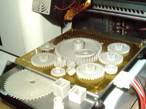
|
|
Alunar R100 Heated Bed Upgrade Successful ABS prints 010318 Pic B.JPG Size : 756.115 Kb Type : JPG |
|
|
Alunar R100 Heated Bed Upgrade Successful ABS prints 010318 Pic A.JPG Size : 866.409 Kb Type : JPG |
|
|
Egg Carton Styrofoam Inserts.JPG Size : 171.021 Kb Type : JPG |
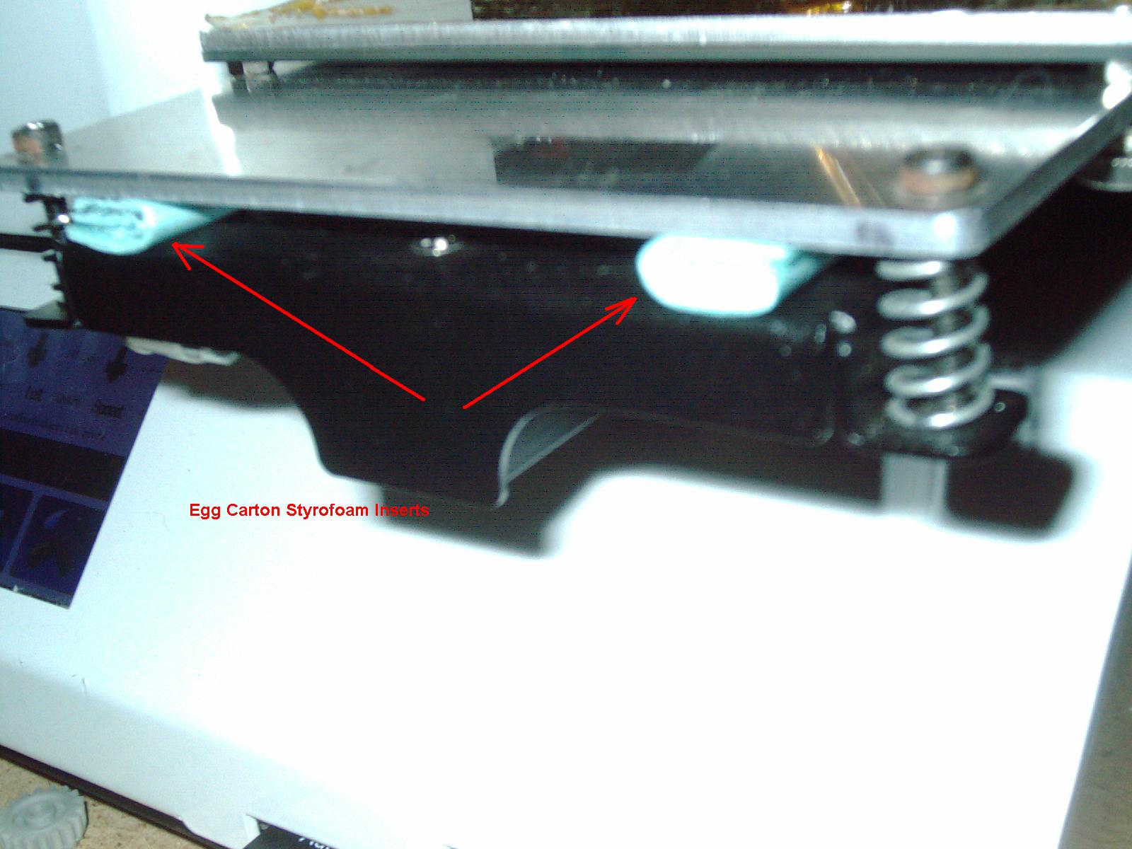
|
|
Alunar Good Settings with Heated Bed Upgrade and ABS 010318.zip Size : 192.256 Kb Type : zip |
As the layer of Kapton tape wore out due to many parts and test prints- I ordered a new roll from big-auction-site for $13 for a 100mm x 100Ft roll. While I was waiting for it to arrive, I experimented with just putting Elmers Gluestick directly on the very smooth surface of the aluminum heated plate. I found that the prints actually turn out better this way. The bottom of the part is very flat and gets adhered well. Also it is much better when trying to remove the part. The Kapton actually makes it stick too much and tears the Kapton sometimes. For now I am leaving a hole in the center of my Kapton tape of about 2-3 inches diameter - which is the part that actually tore and wore from use. I patched it when the new Kapton roll arrived - but the very first print ruined that patch so I removed it.
Also I have been experimenting with "bridging" which is something that my more complex CAD drawings require. I have somewhat switched from Cura to Slic3r software because there are more settings available to tweak than Cura. Those extra setings have alot to do with bridges and overhangs. I have found that I can actually somewhat make overhangs with ABS but Im still learning. I also find that there are more dimensional accuracy tweak settings in Slic3r software which helps me create holes and outside dimensions that are very accurate. Just today I made a thin walled tube-like part on Slic3r software that turned out well, and I tried many times to make a good one on Cura without success. I think that Cura is a good software for certain type of parts - but the type of parts that I make require more settings to accomplish. So far I like slic3r software and has helped me to make a better accuracy part. Of course Im using older versions of both software which runs on my older Windows XP laptop- newer versions may not have those issues.
Here are my ABS settings for Slic3r software which seem to work pretty well for basic mechanical parts and replacement parts. Im not saying its the end-all-be-all but works ok for me on Slic3r version
Update 3/17/18
I have successfully printed a "Marvin" test print with perfect overhangs and the loop was nearly fully formed with very slight imperfections in the loop on his head which I fixed with a utility knife. This "good enough" test print is a milestone and Im posting the Cura 15.04.6 profile here.
Note that I have nver used any other plastic for this printer only ABS. I have no idea how these settings work for any other plastic. I just use the cheapest ABS filament ($10-20 through big-auction-site) which prints just fine.
I have completely discarded some settings from my past experiences. This supercedes all my other settings and etc etc. The major change is I NOW USE THE Built-in FAN. That was the only way to print a "Marvin" Test print because it has overhangs. I feel like I never even tried it because of the advice I received online - that you can ONLY print ABS if you fan is off (false). Well I now know that printing ABS with a fan on is a workable solution. I use a 35% fan which allows "bridging" and overhangs. With the fan off (my former mindset) I could not make overhangs. Also another change is having the printhead move to the side for awhile - to allow that layer to cool. During the "Marvin" loop- the printhead goes to one side and waits until that layer is cooled. Then it starts the next layer ... The loop is more brittle. The rest of the "Marvin" feels like normal everyday plastic. The loop is visually there but easy to crack off. The backside of the loop has some "schmutz" but it aint half bad
I printed directly off aluminum heated bed with gluestick. See actual photo which shows the printbed and the actual print. I was amazed it worked. Very smooth fine details and shimmers like a silk string covered Xmas ornament ball.
1-1/2 years of trying this/that and Im pleased with the result. Im not saying the ini file is perfect. But it is drastically better than my previous settings on formerly "unprintable objects". I have just today removed Kapton tape completely from my printbed. For a long time I was just using the printbed area which was missing the Kapton.
to use this profile for ABS
(save your old profile first as this will over-write your settings)
1. Load Cura 15.04.6
2. In the menu choose "Open Profile"
3. Select this file which I created
|
|
Alunar HB-R100 Cura Settings for ABS w heated printbed mod 031718.ini Size : 10.904 Kb Type : ini |
|
|
Marvin test Print Pic Frontside ABS 031718.JPG Size : 33.667 Kb Type : JPG |
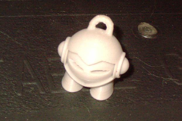
|
|
Marvin test Print Pic Backside ABS 031718.JPG Size : 35.876 Kb Type : JPG |
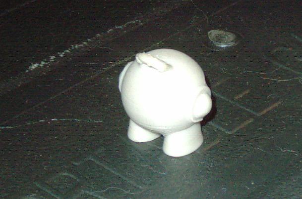
|
|
031718 Marvin Test Print Grey ABS.JPG Size : 775.19 Kb Type : JPG |
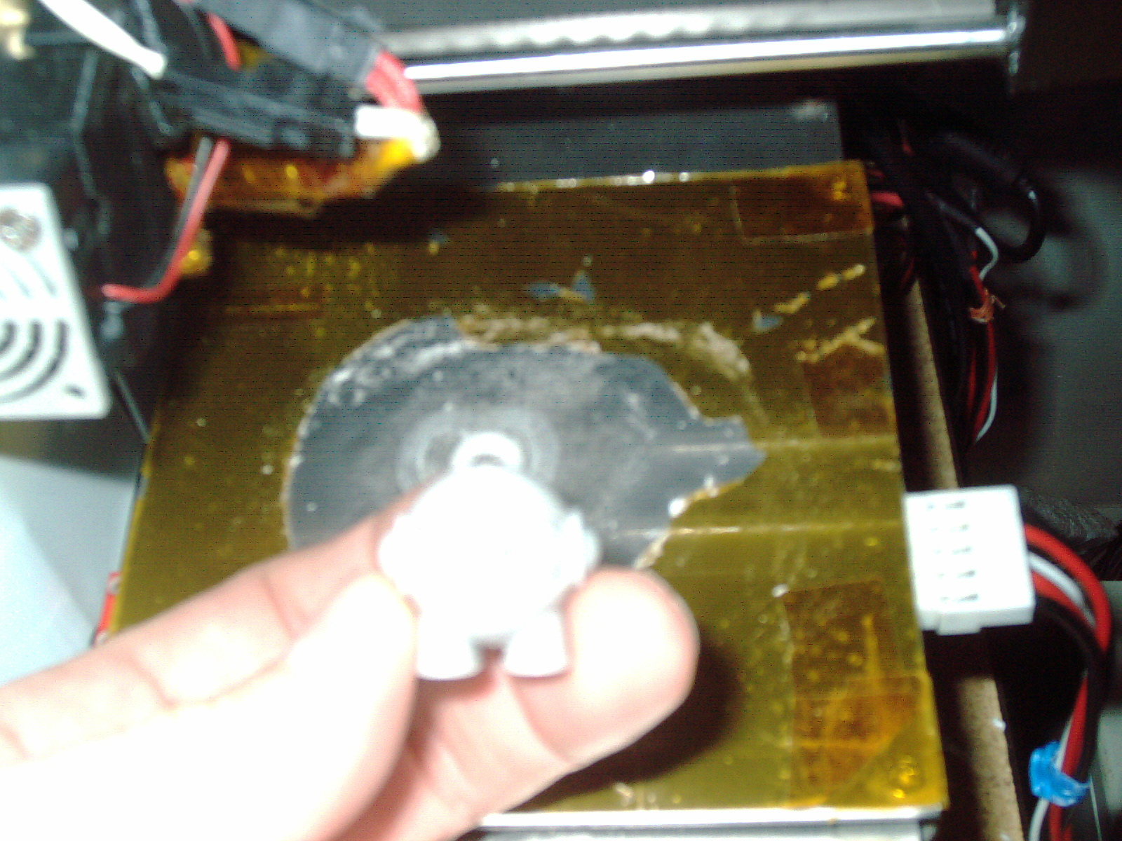
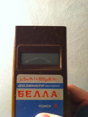
Geiger Counter "Bella DBG-01N" БЕЛЛА ДБГБ-01И
Made in Ukraine or Russia. My unit is brown plastic and some similar models were available in white, red or other colors and stickers. Some units are marked DBG-01i (mine is not marked with an i) Since I dont know Ukraine language - it looks to me like this model should be called Benna or Bevva or gEVVA or bEVVA or who knows what the correct transaltion is. But when I look online - I see that most people refer to this model as "Bella Geiger Counter" and by searching under this - you will find many videos on youtube and online websites selling parts and units.
I purchased mine in early 2015 in non-working condition from big-auction-site. I plan on restoring its functionality and will post my repair here. I estimate the date of mfg is approx 1983-1989. This was a very popular unit and many people used this model during Chernobyl accident to monitor levels. It is one of the industry standard models for obtaining readings and uses 1 internal sensor SBM-20 tube which is sensitive to Gamma rays and X-rays. It uses one standard 9v rectangle battery.
Also see my other webpage
http://www.drviragopete.com/scanning-electron-microscope.php
The other webpage of mine - has to do with restoring a scanning electron microscope. I am concerned about getting irradiated / x rays /gamma rays from this equipment if improperly adjusted. So I decided to buy a geiger counter so I can avoid that harm. SEM microscopes are not considered unsafe as they tipically produce xrays internally but are well shielded. However that is refering to a properly working SEM. Mine is a fixer-upper and I need this geiger counter to make sure I set it correctly and maintain it.
Another good use for a geiger counter with X-ray abilties is testing of vacuum tubes - specifically picture tubes on TV sets. For example obtaining a slightly better brightness on an old picture tube - may make me crank-up slighly on the flyback transformer but only slighlty. See if the flyback is tweaked too high - the filament inside the "picture tube" yoke/neck at a certain poiuntg will produce unwanted xray or other radiation.
Radiation is not a toy and I see too many people using their geiger counter to play with radioactive rocks or other objects while listening to the Geiger counter "going nuts" ticking and beeping its warning while the user handling the samples. I suggest that people who use their geiger counter - should use it to save themeselves from harm -rather than as a toy. Specifically - if the geiger counter shows an unsafe level - take immediate action to avoid exposure or correct it so that the source is put-away/solved safely. Thats my advise.
A reading takes about 1 minute.
My General Operating Instructions Notes
1. Top button is reset (LED will flash as an aknowledgement when momentary button pressed)
2. Rightside Buttons (slide up down switch to select)
A. Upper is Audio Click ON/OFF
B. Lower is Power ON/OFF
3. Place unit at or near source. Press reset to begin new counts. After approx 40seconds the display translate the number of counts into a whole number with decimal point and additional disgits. This number is your micro sieverts per hour. This meter has an accuracy of within 30 percent plus or minus. Gamma and Xray sensitivity only. Use only as a guide and use your own best judgement on what is safe or not. Its not going to pick up every ray or even close to all of the rays that may be or may may not be present.
I can tell that this will be a difficult circuit to diagnose because the IC chips are not in English and the electronic components are different looking apearance-wise and marked in a differnet language. I will need to figure out English equipvalents and use my best judgement and equipment to figure out what is the problem with this non-working unit.
I see normal background safe/normal radiation counts is somewhere between 10 to 25 clicks as typically displayed on this model. It has a 4 digit LCD display which looks like this 8.8.8.8 Often on this model's LCD display there is some black bleeding internally as the liquid crystal seeps or glass separates or cracks etc. I see no bleeding on my own LCD which makes me think it was never exposed to extreme cold. LCD screens are damaged or destroyed by extreme temperatures both hot and cold. I felt that this unit on big-auction-site was worthy of putting time and effort into fixing as it is physically in good shape and complete - right down to the battery cover.
Update 1/15/15
I received my geiger counter and got it to work and un-modded it as much as possible. I have posted a more detailed description of what was done on my "scanning electron microscope" page. It didnt need any electronic component repair or replace. It was just a matter of un-bodging it bringing as close to original as possible.
Update 6/2/16
Unfortunately my Bella Geiger
Counter is not working. I wanted to use it to test a CRT inside my film
equipment which scans using a flying spot scanner - when I went to my
cabinet to get my geiger counter - it was in a ziplock bag and no 9V
battery installed. I put a fresh brand new battery in it and I see all
zeros O.O.C.O and one of the zeros is incomplete "C" due to one of the
LED segments unlit. I see no incrementing or tic tic tic. It is
unresponsive. I pressed the zeroing button on top of the unit and red LED
lit but I see no sensing of background radiation at all. So
unfortunately I was unable to test my CRT inside my film scanner (one of
several extra parts units which I am trying to rebuild/restore/combine
into another good one) which I am currently repairing. I dont know how
it could be non-working as it has been undisturbed in the cabinet and
safely stored. I enjoyed using it and I hope to find time someday to fix
it. I used it about 12 times in the last year and was a very useful tester. I didnt do anything to cause it to die - was just stored in a cabinet.
Update 6/7/16
I decided to open it up and see what is wrong. I tried 2 batteries and still was stuck at O.O.C.O and I disconnected battery and tried moving the bodge wires and then reconnect battery. No change. Disconnected battery and then tried moving all of the components over just slightly - that was it a loose connection on one of the components. I reassembled after it worked. I didnt touch up any solder joints. There is a certain point of - "if it aint broke - dont fix it" Im glad that it works again- one segment of the display shows a C rather than an O but nonetheless - it is useful again. Normal background radiation differ from minute to minute but is somewhere around 7 to 13 clicks. If I put it on a stack of extra floor tiles I get a couple more clicks around 13 to 15 - so I can cell it is working normally and LCD numbers are incrementing now. The mfg coated the PCB and components with a clear coating (varnish? Clear paint?) and I dont wish to disturb that - so it works and Ill not reheat all of the solder connections.
|
|
Bella.pdf Size : 928.26 Kb Type : pdf |
|
|
bella specs.JPG Size : 13.46 Kb Type : JPG |
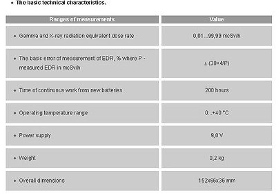
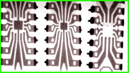
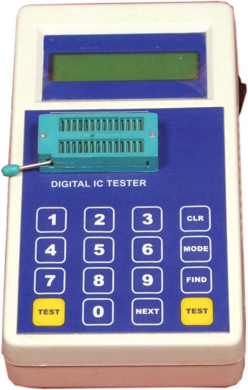
VZ IC Tester pictured above (list of chips shown at bottom of page on left side in blue) My IC Tester # 3
It has search function and chip number can be manually typed using the keyboard. This tester was sold under 2 different brand names. The components on the internal circuitboard are sanded to hide part numbers- which makes repair very difficult as only good working chips are identifiable. The case is not precision molded - it is a heavy plastic which is slightly imprecise - the battery lid does not open/close easily due to this imprecision. Much care in handling the battery cover is needed. The vendor sent me a replacement battery cover at no charge. The vendor was helpful. This is a very nice tester and at the time I purchased it - it was the lowest cost handheld tester available. It does a good job identifying / searching for unmarked chips. I bought mine through big-auction-site. Later this same mode was sold through a commercial online big retailer for more than twice the price I paid for it.
Manufactured and purchased new in 2012 year.
Update 12/15/14
I caution the users of this tester and rebranded/original model which bears a different name. This tester has a very small tolerance for deviance in supplied power. It will blow out if any ordinary power adapter is attempted connected. I suggest ONLY running this IC tester on 9v battery. Internally some chips have been sanded down removing the identifucation of the chips. This renders the tester difficult to fix by end user as identifying a non-working sanded-down chip is not possible. Heed my advice and only use batteries. The instruction manual gives the wrong voltage for the dc power port- dont attempt to connect 9v with a wall type adapter to the external power jack. Heed my advice and only use internal battery.
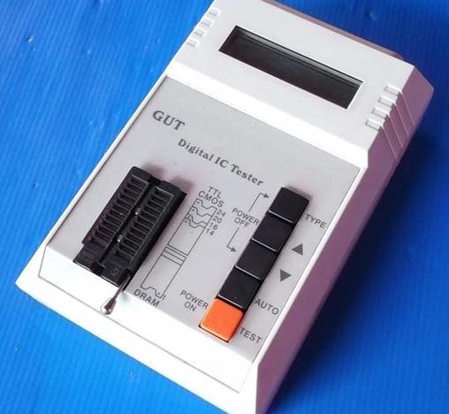
GUT IC Tester pictured above (list of chips shown at bottom of page on left side in white) My IC Tester # 1
It has search function and chip tested can be manually selected from internal Menu lists. This tester was sold under various names by several vendors. The diagram on the front of the unit is handy - it tells you which chips to install up orientation or down orientation. The down orientation chips need to be at the bottom of the socket. The up orientation chips need to be at the top of the socket. There is a clearly marked OFF procedure. (on another brand this off procedure is not clearly marked - see my LIC tester further down on this page)
I bought this used and had a heat damaged LCD display. I ordered a new LCD module which is a standard type. This tester now performs very well and has no cosmetic or functional issues. If I didnt tell you - no-one would know it had been repaired. The only difference is the LCD contrast is higher on the new lcd module than on the original (original LCD was dim) and display has a slightly greenish color.
The aftermarket LCD module was purchased on big-auction-site " HD44780 16 Character x 1 row LCD display w/light " and the original one was not backlit and was damaged as received from seller - bleeding LCD symptom towards the center. A perfect replacement non-backlit (jujst like original) screen choice is 1602 16character x 1 line - instead I chose the backlit version and had to modify the internals slightly to make it fit as it is thicker. I have not hooked up the backlight. It runs fine without the backlight. At this time I have not figured out where to connect the backlight pins - the screen works beautiful but no backlight at this time.
Manufactured approx 2005 year estimated. Purchased used in 2012.
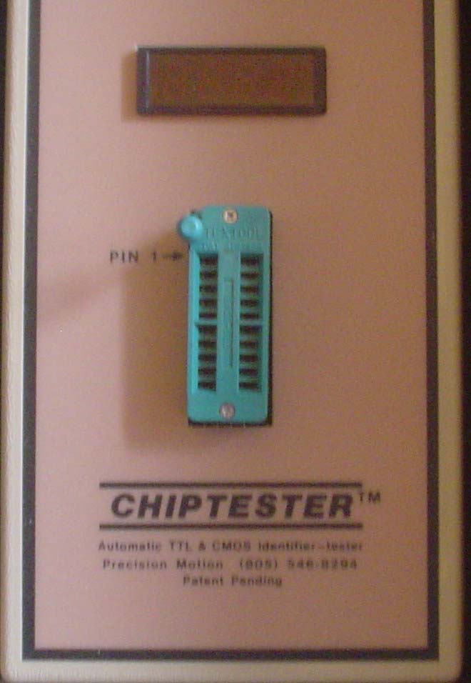
Precision-Motion Chiptester Model CT2 pictured above (list of chips shown at bottom of page on right side in red) My IC Tester #4
Notes: This is the full version machine with optional internal ROM upgrade factory pre-installed (" CT1 with 4164 & 41256 TEST "). Originally sold by Digi-Key Part Number CT2-ND in approx 1988 year. There is no keypad to enter the chip number. Simply insert the chip into the socket. The manual tells you the correct display for a good chip. Usually the display shows the last few numbers of a chip - as the correct response for a passed test. On other chips the display may show a letter and number combination or simply a number or a subtraction symbol next to a number etc - the manual deciphers the display and what it means. Reading the patent also helped me understand what this tester does. It is very sophisticated yet simple for most chips. There are some chips in the list which require 20 adapters to be self-made as some pins on the self-made adapter need to be cut-off or jumpered. I do not have any of these self-made adapters. Between all of my testers - the chips which the Chiptester requires a special adapter to be self-made - are available as part of a built-in test on another one of my machines. It is important to look up the chip number in the manual before plugging it into this tester. Estimated manufactured 1988 approx year.
This IC tester was purchased used in 2012.
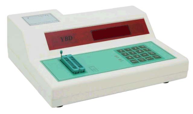
YBD IC Chip Tester pictured above (list of chips shown at bottom of page on right side in yellow) My IC Tester # 2
Purchased and manufactured New in late 2012 year online from a Hong Kong Seller. Purchased the optional add-on 3-socket adapter 2013 year direct from the mfg. No automatic search function on this tester. It has loop function. The number of ICs this unit can test is very very extensive. For some ICs - the chip must be put with pin one at top of ZIF socket - other tests require the chip to be put in with pin 1 of chip to pin 2 of the tester socket (the display prompts the user how to insert after the chip number is entered.) The manual's diagram showing how to use the adapter differs from the markings on the 3-socket adapter - so I have not plugged this $40 3-socket adapter in at all. The mfg is checking on this to see if they can provide me with an updated instruction sheet to clarify the proper use of this adapter board.
Update 2/25/15
The mfg never did provide the missing information (but I did get responses to email). I paid quite a bit of money for the adapter board plus Western Union fees and it added up to be alot of money. But I'm glad to have this board. I have communicated with several buyers of this same IC tester and one of them also wanted to buy this add-on board but was told it was not available. My understanding is that the person who created this add-on board (mfg former employee) is no longer there and the current employees do not know the answer. Also the board was not available for purchase - another owner was told they dont have any more.
So that makes me the only person who actually has this board - possibly?
I studied this board thoroughly and have created an instruction page on chip orientation and orientation to plug into the IC tester. I didnt want to run the risk of just randomly trying things - so I carefully studied the board and determined how each pin on the board leads to each pin on the DIP male plug on the end of the ribbon cable.
The basic purpose of this board
When you type in the chip to be tested from the chiplist - you enter a sequence of numbers corresponding to that chip. For example when you want to test chip 8255 you key in that sequence on the keypad. Usually chips can be tested directly on the console. But for certain chips on the chiplist the display shows OU-1. This display tells you that the testing of this chip requires the "Special Device Testing Board YBD-5" (see my photos of this board). The manual that came with my tester is mostly understandable but leaves you scratching your head on certain topics. Especially regarding the add-on board. So I wrote my own manual for the YBD-5 board. I also put homemade stickers on it; So, I know the orientation of the ribbon cable and orientation to insert the chips into the sockets.
Here are some photos of the board, my own instruction page, and other misc photos showing my actual unit in its protective packing material. It is a very nice IC tester - I spent alot of money on the tester, shipping, bank fees, western union fees, add-on board, etc. Was it worth it - yes I'm glad to have it. I can test chips that are unique to this tester- also it is a good second opinion and pulls its own weight in determining faults.
I had to figure out the answer to my own questions. I was basically on my own regarding this board. I feel that I understand it now and took alot of effort on my part.
What is not clear in the MFG's manual
1. Orientation of ribbon cable and red stripe side
2. Orientation of chips on the sockets
My photos show the correct orientation. The instruction manual explains how to use the add-on board, orientation, schematics/board layout and traces, etc. It is not often I use the chips that the add-on board handles - but I can now refer to my own manual to refresh my memory. I never have to fumble around with this anymore. Now I can use it. I printed the manual on my color laser printer Samsung CLP-300 which I purchased a few years back at OfficeMax on closeout/demo unit. It prints beautiful glossy perfect pages. I use that printer very sparingly only for important things. What I'm trying to say is this is a beautiful instruction manual - I put my best effort into it.
They didnt make 3 separate adapters - but instead combined it into one board. Either way works- but schematically it would be much simpler if it was 3 adapters. The display tells you which of the three adapters to use. But since there is ONE adapter board - you plug the chip into the corresponding section of the board. All this adapter board does is cross and switch around a couple of pins. Its just wiring traces. There are no electronic components on the add-on board.
Dont jumper on this tester (some other testers have you insert jumpers between pins or add capacitors to certain pins) - BUT I WARN YOU - jumpering is not applicable to this tester. Certain pins must be raised and then that pin is crossed to where another raised pin is - basically switching pins around. Thats basically what this adapter does. If you simply jumper - you'll short something out inside this tester- dont do that.
One funny thing about this tester is the word "PLEASE" is displayed when it is ready to test. A better choice of word is "READY" It makes a beep boop type sounds which remind me of a Milton Bradley SImon game from the 1980s.
I like this tester - it tests alot of chips including some older computer motherboard type support chips.
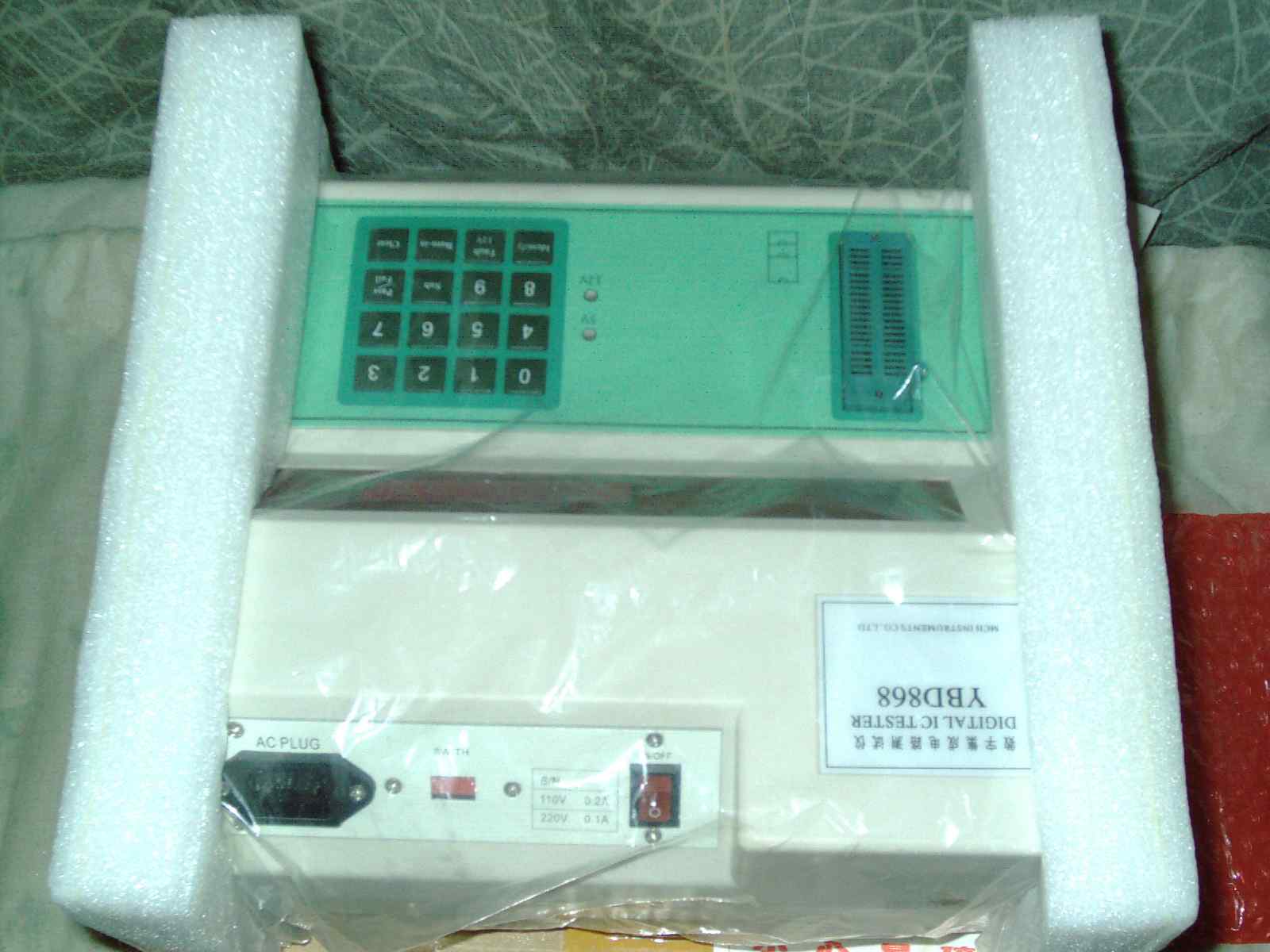
I see a youtube video (not my video) which gives a good basic demo of this tester. The author is speaking in a language I do not understand. I understand English and Spanish and am able to pick out enough similar words to understand this video's narration.
Copy and paste into your web browser
https://www.youtube.com/watch?v=BdoqziGhobo
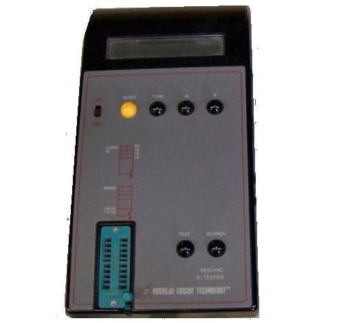
|
|
MCT2.JPG Size : 464.377 Kb Type : JPG |
|
|
mct IC Tester sheet.jpg Size : 81.646 Kb Type : jpg |
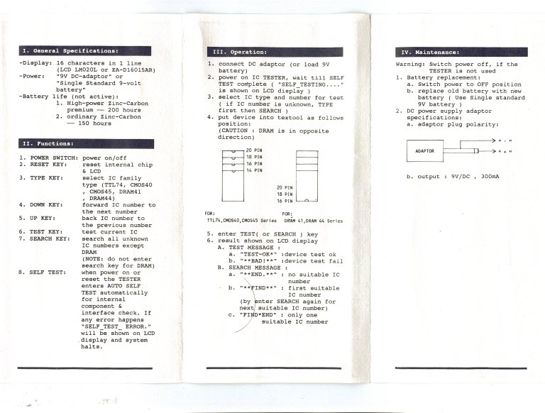
MCT IC Tester pictured above (list of chips shown at bottom
of page on left side in green) My IC Tester # 5
Made in 1989 year approx. Memory chips DRAM are installed in the test socket reversed/backwards and furthest away from LCD. Has auto search function and also arrow keys to select chip from internal list. I have the version with the yellow button (some other units have a red button) Purchased used in 2013 from USA seller. This is a very speedy tester and with a press of a button recognizes a chip and tests it very speedily. You can also manuall\y select the chip number from a chiplist and scroll through that list. It runs on a 9v standard battery. Memory chips are tested upside down (notch facing user) and TTL chips tested up-side-up (with notch facing away from user)
I had 2 identical units and gave one to a family member (both purchased from same seller) Both units had a dim LCD display. Dim LCD is normal for this model. Use it under a good light source such as a lamp.
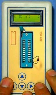
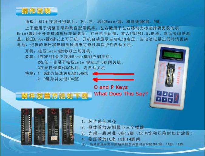
I believe this language is from Singapore possibly? As Singapore is where my TSHG-02F was purchased from.
Translation of the above picture is appreciated.
Update 5/7/15
I received a very vague translation of at least one part of this photo from a big-auction-site seller who wrote that the TSH-06F "P key" is for backlight and the "O key" is for quick power on / off. I was emailed the internals of the "blue tester" and the insides have no backlight on the LCD screen. The internals of the "Blue Tester" show a series of 4 through-holes labeled "pro" and a large odd looking resistor (the rest is surface mount components and ICS) and two adhacent solder points - also the ribbon cable leading to the LCD may have one unused line - if in fact this backlight function was implemeted onto the board. The "yellow tester" TSH-02f (Which I have) has no P key or O key. I see no backlight or prog function in the menus. I have added 2ea zip files here which contain the insides of the 2ea TSH testers. As an interesting trvia - the blue TSH-06F is silk screened on the internal board with the words "ABI Chipmaster"
I wonder if the 4 +2 pads on the TSH-02F and the 4ea "Pro" thru-holes are programming points for adding to the internal chiplist and other functions. The backlight is the least of my concerns as the tester perfoms very well and is just fine with a non-backlit screen.
|
|
TSH-02F Singapore tester instruction Page.zip Size : 2428.26 Kb Type : zip |
|
|
TSH-02F Demo.flv Size : 8893.552 Kb Type : flv |
|
|
TSH-02F Operating Instructions PartA in Color.JPG Size : 64.462 Kb Type : JPG |
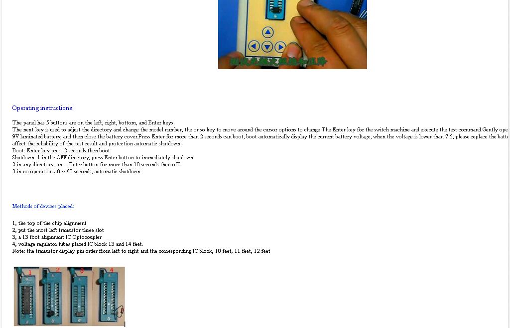
|
|
TSH-02F Operating Instructions PartB in Color.JPG Size : 97.406 Kb Type : JPG |
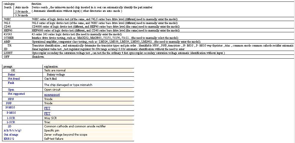
|
|
TSH-02F LINES.jpg Size : 71.439 Kb Type : jpg |
|
|
My TSH-02F Pics.zip Size : 1763.018 Kb Type : zip |
As of this writing I am unaware of the purpose of the P key. The answer is probably contained in the jpg file but since I am unable to read that languae - I dont know what the P key is for. I assume it is for self-test but I dont know for sure that is only a huinch on my part. If you have a blue tester and figure out what the P key is for - let me know.
|
|
Blue Tester Self Test and Power Off O & P.JPG Size : 66.712 Kb Type : JPG |
|
|
TSH-06F tester showing internals.zip Size : 1620.93 Kb Type : zip |
|
|
Black TSH IC Tester.flv Size : 3497.429 Kb Type : flv |
TSH IC Tester pictured above (list of chips shown at bottom
of page on left side in orange) My IC Tester # 6
There was no chiplist included with this model of IC tester - I have created a chiplist for it - see the bottom of pages. I have manually gone through each and every chip in the internal menu one-by-one which was a laborious task. I made notes on which chips it recognized and which ones were not supported. Why the mfg didnt include a chiplist - I dont know - but I have one now because I made it myself - the hard way. This chiplist is identical in both the TSH-02F (Yellow) and TSH-06F (Blue) testers. I used up 1-1/2ea 9v batteries making this chiplist - with no chips in the socket - just going through the menu and looking to see if LCD display has a reaction to manually entered chips to create my own chiplist.
Update 8/23/15
I see 2 sellers on big-auction-site which have the model TSH-06F advertized as a "SainSonic Digital IC Tester" and over 20 other sellers have it at the $40-55 range and do not list any namebrand. One seller has this item listed for $36 and has sold 5 of 6 at this low price.
In response to my "translator wanted advertisement on Craigslist - I received a reply about a month ago with another partial translation - again stating that the P key is for backlight and further stating that he/she would tranlate the rest of the document at another time - but never heard back from them.
Here is a screen snapshot of 1 or 2 ads which states "SainSonic" - I have blanked out the website and sellers name etc to keep it generic.
|
|
SainSonic TSH-06F IC Tester.JPG Size : 95.482 Kb Type : JPG |
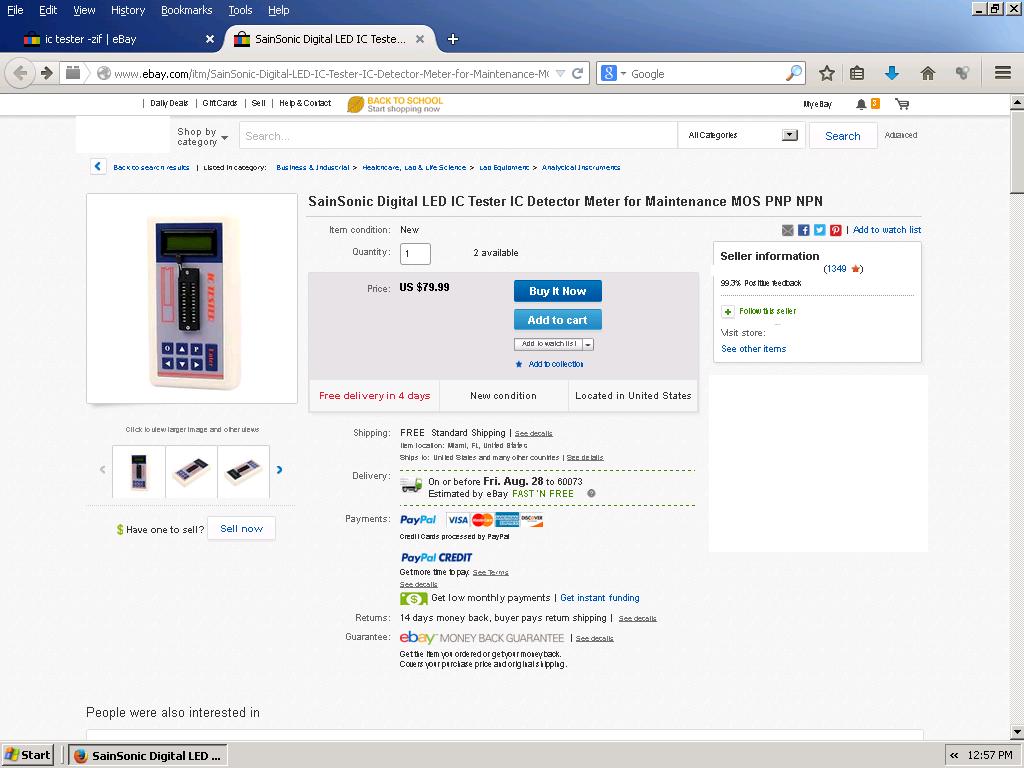
Here is a text file in Word format - you can use an online viewer if you dont have the soft ware "Word" But this is just your average instructions in which it says the P key is for backlight. Another ridiculous online instruction in which it gives false information - can anyone reading this translate the image which contains foreign language text - that may contain better information?

|
TSH-06F Operating Instructions.doc Size : 43 Kb Type : doc |
I finally feel I have a complete answer to the question of what the O & P keys are for. The P key is a backlight and I was told by a person who I have LONG since blocked on my emails as he was writing saying that his TSF-06F doesnt have any backlight and the P key being a backlight on/off makes no sense. He went as far as sending photos of his LCD and boards internally and it is not a backlight capable LCD.
So my only conclusion is that some early versions of TSH-06F are not backlight capable and some have backlight. I can clearly see in the following youtube video - that the IC tester in use DOES have a backlight.
Here is the video (I am not affiliated with this video which has some good repair tips)
https://www.youtube.com/watch?v=DnAzygzyC4A
See in this video - the youtube TSH-06F really and truly does have a backlight. And yet one person has showed me photos of the internals of an early model which does not have backlight.
As I look on big-auction-site - there are at least a dozen vendors selling this TSH-06f and see no photos of the LCD screen with a backlight on. It is unfortunate that the sellers use "factory stock" images and data and didnt take the time to post actual hands-on photos. I hope this update and the video link clarifies a few things about this model's P & O keys and what they do - at least on some versions of this tester.
Update 9/7/16
On big-auction-site a seller is selling 1ea used TSH-06F blue ic tester for a low price. I asked a question by replying to his ad. My question was whether thebacklight worked when you press the P key. His reply, "Hi - I'm not aware that there is a backlight in these units - at least the one I have does not have a backlight that I am aware of and in fact my "P" key does nothing..." I didnt buy this item as Im looking for one that has a working backlight.
My point is that it is very likeoly that the buyer will receive a non-backlight do-nothing-P-key unit. Make sure you ask the seller or vendor to confirm that the P key works and produces a backlight. I have noticed that the price has decreased down to an average of $35 whereas about a year ago these were selling for about $50. Some sellers are still higher than the average. If a backlight is important to you -make sure you get them to confirm that the backlight function works.
Update 12/26/16
I see a youtube video demonstration of the China IC Tester which looks identical to the "Blue IC Tester TSH-06F" in which I have been looking for one with a working "P" button for the backlight. The youtube author is reviewing a China IC Tester (not my video) and mentions that there is no model number and only has printed on it "IC Tester" The video shows the backlight ON when the unit is on. I deduce from this video that the $31.56 big-auction-site IC testers MAY have a working backlight.
TSH-02F Yellow IC Tester (Singapore) - no backlight
TSH-06F Blue IC Tester (China) - backlight button does nothing - no backlight model "ABI Chipmaster on PCB backside"
TSH-06F "IC Tester" - Blue IC Tester (China) - possible yes working backlight "No Model Name on PCB backside"
Im not affiliated with the following video (pardon the derrogatory comments during the video - yikes) Its a beautiful IC Tester and took alot of skill and talent and precision tooling to make it.
https://www.youtube.com/watch?v=vmL4bZlsFu0
The outter apearance of the case DOES NOT indicate model number and only difference seems to be "ABI Chipmaster" printed on PCB or NOT. Also internally the LCD screen either has a backlight or not.
Ive not had any success in getting a response from big-auction-site sellers - on whether their unit has a backlight or not.
Buyer beware of sellers of old generation Blue IC testers - trying to trick newbies into buying a non-backlight model. It is possible that simply replacing the non-backlit LCD to a backlit LCD screen will upgrade the previous version fully - But that is only speculation on my part. I do not own either version of the Blue IC Tester from China.
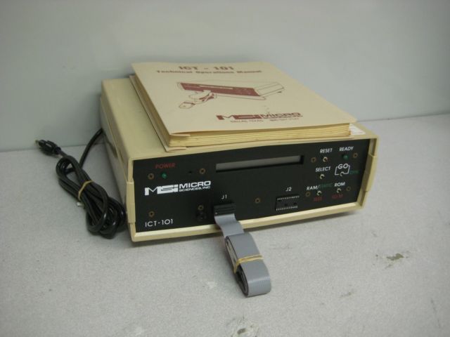
Micro Scences MSI Digital IC Micro Circuit Tester Model ICT-101 (pictured above)
IC Tester #7.
(List of chips left side purple color - see below)
There is an empty socket on the front of the machine - which is for 24-pin IC chip clip (was optional accessory - but mine doesnt have this clip. As I read from the book this optional clip is only for 74154 IC which is a narrow .300" IC same as most 7400 chips so a special .300" IC clip 24-pin is needed and these clips are uaully designated "24/3" to denote 24pin clip for a standard .300" narrow IC). I have 2ea total IC testers that can test 7400 TTL and 4000 CMOS chips in-circuit while the circuit is powered on (the MSI ICT-101 and the B&K 560). It is a large tester 5"x12.5"x11.63" and weighs 7.63lbs. This tester is estimated to be mfg in 1983 and is complete with manual and ground cable (Pomona Electronics 3780-36-0) and 20-pin ribbon cable with end clip. Most of the internal chips are 7400 series with 1 static RAM and several ROMs. There is a D800 microprocessor in there also. A board which looks like a memory module is covered in factory black epoxy resin to shield the part numbers and protect from anti-static. The 2ea upgrade ROM which adds a few more ic chips to the list - is not in my machine (I have the standard ROMs with 2ea additional empty sockets for the upgraded ROMs to go there. My sockets U10 and U13 are in need of the upgrade ROMs. If you can provide these missing U10 and U13 ROMs - let me know. I realize it will be difficult to find these ROMs 35+ years later.
Here is my photos and description of how I fixed my ICT-101 Tester. It is a free download and copyrighted All Rights Reserved. Do not post it in forums or share in any way. Instead - refer people to this page or give my contact info so they can download it from my webpage directly.
Update 5/29/15
I have acquired a second fixer upper ICT-101 (purchased Oct 2014) which has the 204 Rom Extended Chiplist stored on 5ea 2732 EPROMs. I am still looking for a 205 chiplist which is enhanced even further. As I work on repairing this second unit - then I can take advantage of additional testable chips- above and beyond the standard chiplist.
|
|
ICT-101 Repair scrambled display & unresponsive.zip Size : 2342.614 Kb Type : zip |
|
|
24-pin Ribbon Cable.JPG Size : 123.288 Kb Type : JPG |
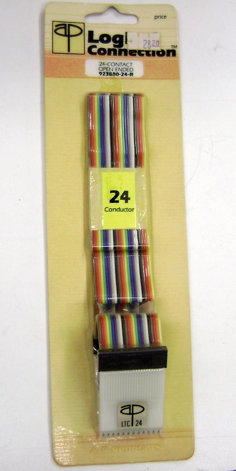
|
|
Amphenol FRC D24 5 24-Pin.JPG Size : 311.042 Kb Type : JPG |
This IC Tester has internal diagnostic checks and functionally tests itself in many ways when powered on. The menu lets you choose settings for ROM RAM CMOS TTL and more. My tester does not have the optional RAM/ROM test feature. My tester is a basic model and only for in-circuit testing of 7400 and 4000 series chips (this tester does not test every chip in these series/families of chips). The add-ons were not purchased by the prevous owner and this is a factory stock machine - now fully functional - after I replaced about $25 worth of discreet (common solder in place type) components and 2ea ICs purchased online. When I purchased it - it had a scrambled/garbled display (looked like this @#$%&*@# with all random characters) and was unresponsive to key presses. It had a bad transistor in the display board and a bad SCR and 2 bad 7400 series chips. The 1ea desoldered/now socketed static ram chip 6116 tested fine on my tabletop IC tester. Luckily the proprietary memory board was fine as the factory covered it with black epoxy and would have been difficult to remove epoxy. Since all of the chips were soldered in place - I had to make my own IC desoldering tool by hand and I removed each chip and socketed it. I checked each componenet one-by-one with a parts tester BK Precision BK815 & various handheld & tabletop IC testers shown on this page. The zener diodes I tested with Duoyi DY294 tester & TSH-021 IC tester which gave correct voltage checks (see above photo which shows germanium diode inserted into IC tester for voltage check) Several parts were replaced with NTE brand replacement parts purchased from Radio Shack online and a couple of parts were purchased online internationally. I desoldered chips carefully and used the same chip to go back into the IC socket. I did not destroy any chip when I desoldered with my homemade desoldering tool and was able to test them on my IC tester and knew they were fine. The online auction I purchased this ICT-101 IC tester from says it was "military surplus". the preevious owner attempted to fix it and boogered up alot of things. It took alot of un-boogering to correct. I solder very well and my solder joints look pefect.
The general concept for using this tester is - you have to have a live powered-on board to be tested. But the board under test cannot be underway. What I mean by that - is the electronics have to be idle and not operating. Powered on but not operating. The microprocessor should be removed or the crystal disabled so there are no oscillations. The ground is connected from the powered on board to the ICT-101 tester. Very important - the ICT-101 needs to be powered on first before any connections are made. It tests CMOS and TTL Digital Logic ICs in circuit on live boards which are not underway. I hope I explained sufficiently - what I mean by "powered on but not underway" as I'm trying to phrase things in everyday terms. The book calls it "the board has to be in a static condition" and "devoid of active ICs" and "effectively removing disabling or tieing clock generators."
The tester should never be exposed to 6v or more (6v would kill the ICT-101 tester). Check voltage (This is a 5v tester only) before testing and removal of oscillations prior to use. The tester should not be clipped onto a chip more than 1 minute or it may weaken or ruin that chip. A sense of urgency in quickly testing a chip is necessary. You cant stop and answer a phone or shuffle papers while using this tester - otherwise you will burn out the chip under test - or damage the tester itself. Any possible future repair should be easy now that all the ICs are socketed. Test equiment should always have socketed ICs - that is my opinion - as it makes for easier repairs and fault-finding/troubleshooting. It is interesting that the mfg of this ICT-101 tester had a lifetime warranty on this tester and is no longer in business. The book states that an ICT-101 is necessary to troubleshoot an ICT-101. So it takes a tester to fix a tester. If I had another in-circuit tester - I could have removed the microprocessor, clipped on the test clip, and checked each IC one-by-one. That would have caught all of tha bad parts except the SCR- which would still have needed to be manually desoldered for testing out-of-circuit. I have alotof IC testers as a "second opinion" about a parts condition is helpful and avoids false pass/fail and replacing good parts un-necessarily. This in-circuit tester is one more "second opinion" about an ICs condition.
This IC tester was purchased used from a USA seller in late 2013.
Update 8/5/14 I have completed the machine by addiing a second ribbon cable in the righthand socket. I found a professional 24-pin IC clip and ribbon cable made by Logic Connection which is NOS New Old Stock purchased from big-auction-site. This clip was hard to acquire as it got lost in shipping for 3 weeks and ended up in another country. The honest person who received it - sent it back to the seller, and then I received it after about 3 weeks. I also added a 24-pin ribbon cable connector. This now gives me the ability to test just one 24-pin IC chip on the chiplist which is a wide style chip.
Update 10/15/14 I have purchased a 2nd identical unit from an international seller. This unit was the sellers 2nd unit and didnt work- it had a scrambled display for example &%&%$@# is what it looked like. The seller then disassembled it and never attempted a repair and it sat in his shop for 10years disassembled. He sent me photos showing all of the major parts like boards and case and front and back panels. I have included those photos here which shows the as-is condition. I will chronicle the repair of this unit here. I suspect it has the same or similar bad components as my other ICT-101 tester repaired with the very same symptoms/issues. I suspect this model must be turne on and off very carefully with no bounce in the power switch otherwise the same discrete components and ICs fry - see my above article on which parts were replaced on my other ICT-101. I will need to wait a month approx for this non-working disassembled tester to arrive.
Upate 11/4/14 I have received this second ICT-101 and arrived from Brazil seller. The box was shipped very carefully and nothing heavy was placed on top. All of the parts arrived as sent with no shipping damage. All boards have corrosion and I knew the condition as the seller sent photos. It will take alot of work to restore. I am glad that all boards and small pieces were sent including all screws in a plastic bag. I look forward to having a working second tester of this model.
|
|
ICT-101 Broken Unit Purchased Oct2014.zip Size : 14287.619 Kb Type : zip |
|
|
ICT101 Auction Pics.zip Size : 1384.474 Kb Type : zip |
|
|
Price $1295 showing ICT-101 Inline Test Systems wrong mfg name.pdf Size : 137.865 Kb Type : pdf |
I see some reference to " backdriving " or " back driving " or " node forcing " which basically means in-circuit testing. I dont own a Boardwalker - but I have 2 other models/brands which do in-circuit testing ( MSI ICT-101 and B&K Precision 560 ). Or as some websites call it " backdriving " in order to test the IC. It's a great feature. It is amazing how few components and basic off-the-shelf ICs are used internally in these testers. The downside is backdriving puts stress on the IC being tested. My MSI ICT-101 manual warns to only leave the IC clip on for maximum 1 minute or damage to chip or the tester can result. The online articles about backdriving show alot of math and circuit diagrams and make it sound so tedious and complex. These testers do that very easily and quickly- the results on the LCD display is instantaneous - it finds the IC and identifies it very easily and immediately - no lag at all.
|
|
Boardwalker 102.JPG Size : 27.337 Kb Type : JPG |
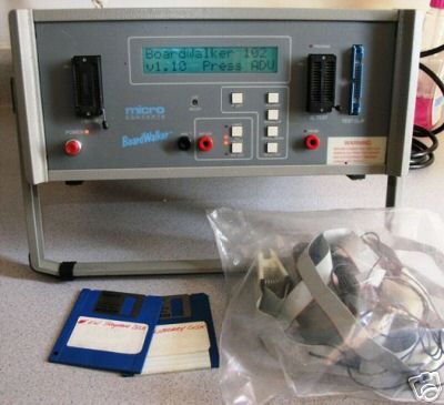
I spent a few hours cleaning the ICT-101 which I purchased from San Pao Brazil Seller. I purchased it in 2014 and didnt know what to do with it until today. I was fearful of bugs or other contaminants as it looked it it was left outside disassembled. I purchased a big plastic storage container from "Dollar General" store for $9 and used about 2 gallons of water and about 1/2 quart of Green Cleaner. I used a small paint brush to gently scrub away all of the dirt and particles. I have cleaned every part as much as possible and then rinsed in water and let to dry. I was careful with the switches and transformer and speaker - not to submerge in water or liquids. Some boards like the LCD board and the power supply board were not disassembled - I used cotton ear swabs to gently clean as much as I could safely.
I removed the socketed CPU and Socketed 5ea Eproms and put them on a scrap styrofoam piece labeled with a magic marker - with a diagram on where they came from and orientation. I will save these ROM images (I will not post the ROMs) as a backup in my records because ROMs do go bad. I am hoping these are the extended ROMs with an extensive chiplist. The stickers are illegible and I will need to put new stickers on. I was careful not to clean the ROMs or expose them in sunlight for too long. I cleaned the board - with all ROMs and CPU removed.
This was a nightmare project that I wrapped in a shopping bag (as soon as I received it) and sealed airtight with clear packaging tape since 2014. I wanted to make sure there were no bugs or other critters. Also one thing that has been on my mind for many months - which I solved today. The memory board has several rows of SIL single inline connectors. One of the pins was broken off and jammed inside one of the female connector holes. I was thinking about this problem for months. Today I came up with a solution - I used a sharp utility knife to gently pry up on the tiny pin - it was wedged in there. I got it out. Look at the photos - you will see a tiny metal sliver along with the screws. That is the pin that I got out. That is a great relief to have this unity cleaned and drying and the pin out of the hole. That broken off pin is probably why the previous owner never finished the project. He included a replacement inline connector - but it was a very difficult thing to remove that stuck pin. It is SUCH a relief on my mind to have this cleaning done.
Here are some photos in zip file.
|
|
clean ICT-101 Brazil 052515.zip Size : 9903.353 Kb Type : zip |
I received a tracking number from Italy seller today regarding a third ICT-101 which I purchased. I saw it on big-auction-site from Italy and somehow it showed up on google search (I search several times a week for IC tester auctions) and by some freak occurance this showed up on google search for one day. I paid the asking price and then was refunded same day - seller stated that she was offered a higher price. Then I replied that I can offer more and she basically doubled the price and sold it to me. This is a working ICT-101 which is 240 volts and she posted photos showing the LCD displaying properly and powered up and also includes manuals. It was shipped by the seller today 5/25 so I look forward to its arrival. My hunch is that the transformer is probably the same as 120V version ??? and by re-arranging the solder points on the windings - it can be changed to various input voltage. I will take photos of the 240v ac transformer when ICT-101 from Italy seller arrives.
|
|
ICT101 Italy Pics 0515.zip Size : 1563.903 Kb Type : zip |
After letting the boards etc dry fully (after a thorough cleaning) I did 2 things today
1. Performed a general Lissajous testing on boards and power supply
2. Made a backup of my 5ea Eproms 2732 and saved to my computer
I see that every component on the power supply gives a vertical line Lissajous pattern- this tells me that there is a short present. It is strange that EVERY component I check gives a vertical line.
When I check beyond the power supply - I see the large mainboard has several component which test normally and chips give a normal reading.
I checked the LCD display board and found an odd reading on the LED which is a vertical line. Also some soldering looks very homemade and some solder joints look like someone started to use solder sucker.
This tells me that the power supply has an issue and the LCD board has to be resoldered as some pins on the LCD look like they may not even be protruding through the hole?
My 1st unit was a unit purchased from big auction site - it also had VERY VERY bad soldering - it possible the mfg did that. It looks very unprofessional - but there is a point of overdoing it and as long as it works - thats the main thing. The old solder is difficult to heat and uses rock hard flux - yikes.
When I copied my ROMS - I had to figure out the Willem 5.5C settings for the 2732 Eproms. I made notes (as I always do) on this chip - so I dont have to figure it out next time- I can just refer to my own notes. The Willem is a good program - but it doesnt give all of the board settings. I had to figure it out and also voltage for the chip. I was glad to see that my ROMs for the Brazil ICT-101 tester are actually the Extended ROMs - this has about 26 additional chips above and beyond the standard. So, I would guess that the ROM version is 204. I dont have the greatly extended ROM 205. But even so - I am glad to have the 204 chiplist now. Every little bit helps. The version was printed on the sticker found on each of the chips - but due to the previous owner leaving it outside - the labels look tattered and unreadable. THe only art that is readable is 84. Inside the ROMs I found a date code of 1984. Also I can visually see a list of chips (viewing the BIN files using Notepad) including 74299, 74653, ... 74245 etc which confirms that yes I do have the 204 ROM chiplist.
I removed the power supply and checked the components one-by-one using my Bk815 and caseless tester and Fluke mulimeter and Beckman Scopemate2. I was alarmed that the Scopemate2 showed a vertical line on all power supply components - so I tested each one strategically removing it from the circuit. When I tested the parts out of circuit - it tested normally. Regarding the vertical line- I would say that it is just how the components are arranged that is causing that reading.
I found 2ea bad parts in the Power Supply
1ea SCR (2N6395 substitute NTE5552) which even my caseless tester cant identify. I tested it on my Mosfet tester and it gave a strange result - usually when I press the button - the red light comes on. ANd when I let got the red button - the LED turns off. Well it is opposite - always lit and when I press the button it turns off. It did look right to me so I have further tested it and looked it up in the book and eve my caseless tester doesnt know what to make of it. It is a bad part - and needs to be changed. The second bad part is a big heatsink transistor 2n3055 and I had a couple in stock. I suspect when I fixed my first ICT-101 I proabably ordered a few extras. One of my instock 2n3055 is bad (maybe was the one in there that I changed out?). The Brazil ICT-101 has a 2N3055 which tests 17 on Hfe gain but it has .08 leakage- and the replacement has 11 hfe gain and 00 leakage. Even though it looks brand new it could be a used one. Nonetheless - Id rather have one that has no leakage. So that is a bad part and needs to be changed out. Now it still is functional with a leakage - probably but I dont want to push my luck as it may weaken some other part. So it needs to be changed. Im glad I had one in stock.
Also I found a solder point which had a copper island which was detached from the PCB. I used epoxy and glued it back on. Then I scraped 1/4" of each side of the copper trace and soldered the bridge. Leftover hoopla from the previos owner's unsuccessful attempt to fix it. At this point I have not even attempted to plug it to AC power. I will go through everything first such as checking wiring of transformer - fixing SIL pins, checking chips etc.
I noticed that the power supply underside has a chart which indicates which pin is for 120V and 240v and 100v etc. So this powersupply is universal worldwide but it need to be wired a certain way. I will make sure it is wired the same way as my working ICT-101 unit. It apears that this one is set for 120V - so the previous owner must have run it on a voltage stepdown transformer. It is un-necessary because it is internally capable of any voltage conversion.
I have gone though 100% of the power supply and at this point know all the rest of the power supply parts test good.
Update 6/9/15
I received the Italy ICT-101 unit a few days ago- I left it for a few days due to the weather. I noticed that the box when tipped made a "clunk" sound and I knew that something inside the box was banging around. I disassembled the shell and found that the seller had unscrewed the transformer/power supply and was just banging around in there during shipping. Fortunately I got REALLY LUCKY that shippers were not rough on this box. Even though the outside of the box looked like an accordian - it didnt get tipped or jostled much. Nothing was broken - only a few wires were pulled from their crimp connector spade ends. I re-crimped the ends back on - reusing the old spade connectors. The only thing I found missing was a tiny washer - which I have plenty of nuts/bolts/screws/washers in my workshop. I spent a couple of hours cleaning mud off the ribbon cables and case and book. Heres another IC tester that spent some time outside in the mud. But I brushed ou the very minor debris - was in drastically much better condition than the last one. I ran out of daylight at 9pm and will have to finish cleaning the LCD front panel assembly another day. This Italy unit is a 240V. The Brazil unit was a 220V unit. I made careful photos of each one. It is unfrtunate that the 2 wires were disocnnected from the spade connectors on this Italy unit (blue and brown wire) and I will have to use my best judgement to decide Left or Right. I will base my decision on my 2 other ICT-101 units and hopefully that will be correct for this unit also.
I got cheated severely by the seller. But I can fix it. Isnt it terrible when people do that to buyers? I never do that kind of stuff to other people. The main thing is that the memory board is present and all boards are present. The ROMs have 204C sticker on it. It also came with the ground wire/clip end and 20-pin IC clip and ribbon cable. Almost every single part is common and replaceable on this tester. It is VERY serviceable wih just off-the-shelf parts. Im very pleased to have it. I even have a manual which is slightly different than my 1st units book. I now have 3 testers and 2 books. All of my units have zero rs-232 ports on the back. I am confident that I can change the 240V and 220V units to 120V. The newest manual has a diagram for voltage changes - but it doesnt show 120V. I have a REAL unit with 120V (that I repaireed) so I can just look off of that unit - and see how it was done. I got very lucky no boards were broken by the heavy transformer/powersupply banging around in there. There are some scraches on the board below the power supply. the top of the transformer has a very beaten up sticker (I straightened it as much as possible) and the model of the Italy transformer is the EXACT same as the Brazil transformer. They are idetical units. I feel that the Bazil ICT-101 is probably a very early model because the memory board is not green and the epoxy covering it is kind of rubbery or sticky. This newest Italy ICT-101 has identical looking memory board to my first unit. My hunch is they are all electrically exactly the same. I see the very same components on the power supply and boards. Same layout of parts. Same bodge wires under the board. This Italy ICT-101 has a MUCH BETTER soldering job than the other 2ea units. It looks nice and neat solder joints on the LCD front board/panel. I cant begin to tell you how awful the 2ea other units solder job looks. I didnt do that - it came that way. That solder it also doesnt want to melt at standard temps.
I see some crud in between the LCD panel/board so I will use an aircompressor to blow it clean tomorrow. I ran out of daylight so that will have to wait. I reassembled everything as it showld be - after cleaning and repairing wires and straightening the transformer sticker etc. I scrubbed all the muddy ribbon cables and the 2ea white plastic rectangle spacers that go below the transformer. It looks nice now. Why in the world do sellers cheat like that? After about 3 hours of work - I am very pleased with what I see. I got very very lucky- it could have been all in broken pieces. Yikes.
At this time I have 2ea ICT-101 on my workbench open. The Brazil unit I am not done with figuring out which parts I need to order. With the Italy unit Im hoping that it will power up after I change the AC cord to a USA 125V cord (I will use a PC AC cord with the end cut off) The seller sent me photos showing the unit powered on. I hope that was a real and legitimate photo of this unit powered on.
There is no way I coul;d have plugged in this unit without extensive work for 3 hours. The screws were wedged under the bottom circuit board, wires disconnected, transformer not mounted. If I would have plugged it into my 220V transformer I would have blown boards, powersupply, and my step-up transformer. I wasnt going to risk anything by trying - Im not a gambler - I dont take chances. I decided to disassemble the unit completely and do what I did to make sure it is clean ad properly assembled - with nothing out of place or missing. It is no longer a disasster mess. It now looks very good.
I spent about 1-1/12 hours cleaning up the front panel with about 15 q-tips ear swabs and green cleaner (saved some from the cleaning tub and filtered it with several coffee filter for reuse) The panel is nice and clean and I thoroughly cleaned the ribbon cable and in between the front panel and the circuit board and all over. As I was carefully and slowly prying off the 20-pin connector which goes to he front of the panel - 2 pins got bent/ It was slightly rusty in there and didnt come out smoothly. When I tried to carefully straighten the pins - they both snapped off. The metal was brittle (I can tell this tester spent some time outside and probably caused the metal to corrode/degrade). I spent a good hour or more trying to locate a replacement 20-pin connector. I tried big-auction site and some sellers wanted big money for this type of connector $13-26 each and not even the right pin count. I went to DIgikey website and found 3M and AMP and several other brands from between 1.60 to $3.10 each and some gold plated - I bought that gold plated one. It was a lucky find because you have to use the right wording. I ordered Digikey part number 1-746611-0-ND and with US Post Office First Class mail shipping - my total came out to about $7. I was lucky to find a good substitute. The moral to the story is that this ribbon cable should not be removed - it is prone to get broken. One that ribbon cable and 20-pin connector are installed - leave it there. When it arrives - I will snip off about 1/2" of ribbon cable from the end and then install the new 20-pin replecement connector. Some sellers call it a Header, IC connector, DIP, AU DIP, Conn, 20 POS, 20-pin, 2x10, .100 x .300 All kinds of copmbinations of these wordings. It seems that all vendors refer to this type of connector - in a drastically different way. I will need another one - to buil a cable for my third unit. But for now I just ordered one.
|
|
ICT-101 replacement plug for ribbon cable Digikey 20-pin Male IC Header .100 x .300 1-746611-0.JPG Size : 172.441 Kb Type : JPG |
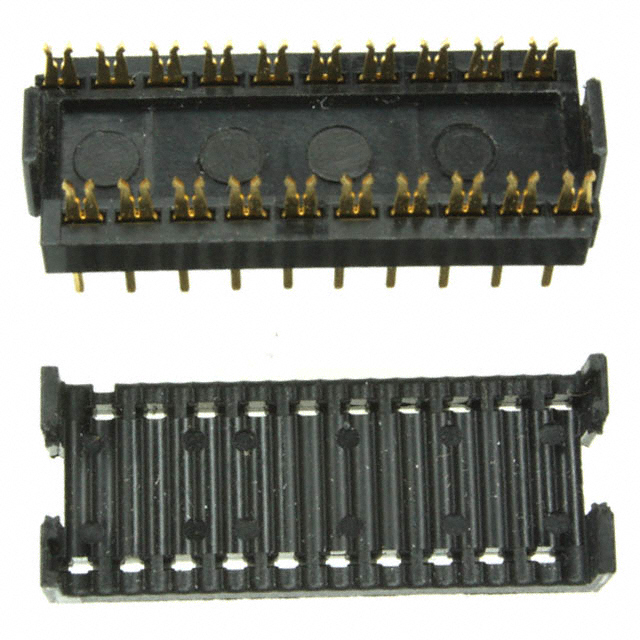
Update 6/15/15
I tested a brand new NTE5552 which I bought to replace a 2N6395 SCR and I found that the new part gives the same strange Lissajous pattern vertical line. Also my SCR tester gives the same LED lit then when the button is pressed the LED goes out for as long as the button is pressed on the tester. This LED response on the tester is opposite of normal. I made an error in thinking that the original part is blown - when in fact the 2N6395 wasnt blown. SO I ordered a $6 replecement part for no reason. It happens to the best of us- I try to keep the misordered parts to a minimum. I put the new part back in its package and will save it in my inventory. So I would consider the power supply fixed at this point. I thought 2 parts were bad but in fact only one was bad/weak which was a 2N3055 which I had in my inventory which replaced a .08 leakage part with a 00 leakage part. Power supply repair is now done. I need to rewire the transformer from international voltage to 125V AC US standard.
I usually make a detailed notes sheet when I am fixing something. I put the pinouts, measured values, notes etc. I will include the scanned notes pages here which shows my diagnostics on all the components on the ICT-101 power supply.
|
|
ICT-101 Brazil powersupply repair 1.jpg Size : 240.652 Kb Type : jpg |
|
|
ICT-101 Brazil powersupply repair 2.jpg Size : 397.526 Kb Type : jpg |
I spent quite a few hours late-night converting the Italy and Brazil ICT-101 units to run on 120V AC USA. I am fully done with one unit's power supply. It has a PC power cord which I found in my inventory parts and cords etc. Actually Im very surprised to find an exact match for the cord - it has the very same 120V plug in every detail. I measured the length and cut down a PC cord so it is EXACTLY the same length as my first unit wjhich came with a factory installed cord.
When I powered up the Italy ICT-101 - I noticed that the self-test did not comnplete fully. It gives a error message "Interface Bad" I can clear this error by pressing reset and then the menus respond normally. I do not have my ribbon cable connector so I cannt test an actual chip to see if the tester performs fully. The error may mean that a component on the boards is bad. The power Supply provides 4.63V at the rear red/black connectors. My working unit gives 4.75V which is probably close-enough. I feel that the power supply is OK now.
I used the opportunity of a semi-working unit - to test the display board from the Brazil unit - which is not as far along. The display is a 16character 5x7 dot matrix alpha numberic LCD. It uses Hughes H0551 and H0550 ICs which are proprietary. I see that the Brazil LCD display shows the first 2 characters properly. The third character is 50 percent working and the remaining 13 characters are not working properly.
I looked at the solder joints and they are horrible and tnkered with by the previous owner. I compared the display panel boards by Lissajous pattern and found that all three display drivers are bad. The working display panel has a zig-zag lissajous pattern on all pins. On the partially working display panel assembly - most pins show a zig-zag lissajous pattern but some show a L shaped lissajous pattern or some are unresponsive. The solder joints are just horrible and just barely connecting. Due to the sensitive nature of soldering onto LCD glass panels - I cant just solder all of the connections- too risky. So I made a mark next to all pins which dont respond normally - next to all connections on the display panel solder joints. I will resolder only those joints and it may have a beneficial effect on the number of characters displayed. But still there are definite drastic differences when I compare lissajous pattern of the working/partially working - so there is a definite problem within the display driver ICs.
|
|
Brazil ICT-101 faulty display A.JPG Size : 844.396 Kb Type : JPG |
|
|
Brazil ICT-101 Faullty Display B.JPG Size : 821.896 Kb Type : JPG |
|
|
Brazil ICT-101 Faulty DIsplay C.JPG Size : 815.839 Kb Type : JPG |
|
|
Brazil ICT-101 Faulty DIsplay D.JPG Size : 816.361 Kb Type : JPG |
|
|
Brazil ICT-101 Faulty DIsplay E.JPG Size : 729.331 Kb Type : JPG |
I made some notes on the transformer wiring for the 120V 220V and 240V configurations. The underside of the power supply shows a chart for configuring the jumpers and output lines for various voltages.
|
|
ICT-101 Power Supply Underside Voltage Wiring Chart.JPG Size : 736.423 Kb Type : JPG |
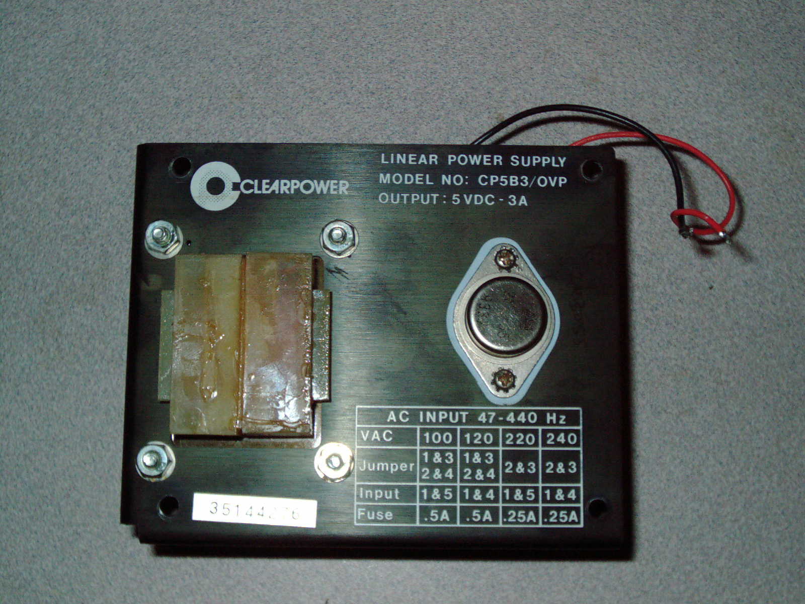
I finished repair of the Brazil ICT-101 and is now fully functional. I did some extensive testing with it and side-by-side comparisons with my USA ICT-101 and now works and looks equally well. I have moved the Italy ICT-101 display panel assembly over to the Brazil tester in order to complete it. I feel very tired and very glad to have a second unit as a spare.
I spent the last few days doing work including the removal of 2 chips on the mainboard of the Italy ICT-101 which gives a strange "interface bad" error at the conclusion of self-diagostics test. I have socketed 2 chips after carefully removing the ICs. I have put back the same ICs into their sockets and get the same results as before. Since I have a massive quantity of 7400 chips purchased from a local shop about 10 years ago which closed- I decided to go through one of these boxes and sort the chips using styrofoam sheets as a temporary holding area- I then moved these sorted chips into their components cases. I am about 1/2 done with this sorting process - I estimate 2 thousand chips or more per box. I have definitely found in-stock replacements for the socketed chips. It is interesting that my out-of-circuit IC testers test the socket chips as being good- but my ICT-101 units - they sense some flakiness in these chips while powered on in-circuit. Sometimes these chips are misidentified and sometimes identified properly. WHen comparing a workiong mainboard - the ICT-101 identified these same chips easily and quickly. This tells me that the socketed ICs are bad and the 2 adjacent chips are suspect also.
I also spent some time researching replacemet IC chips made by Hughes and see in their "1984 Hughes CMOS Databook" found online as a pdf file - I see that the 0551 and 0552 are LCD drivers and I searched for replacements looking through many pdf files and online datasheets. I found no substitute for this IC - it is very unique and sophisticated - very much like a ascii terminal on a chip. I see that it is a hard to find chip. I have requested an online quote from an online source which states that they have a few in stock. The hunch that I am making is that the "HC0550-0-P-000" and "HC0551-0-P-000" is the same chip but just has a different part number. The original part number on my board doesnt pull up any results online. After much research and trying various searches for incomplete part numbers and then verifying pinouts and descriptions. It is my hunch that this is a match for the chips I need. I hope my hunch is correct and that the price quote isnt astronomical. Here are some photos of my display board assembly's PCB showing the 3ea chips which test bad and this LCD board only display the first few characters- the rest are just black all-on characters. The Lissajous patterns on these ICs shows me all 3ea ICs have internal issues and shorts on several legs.
My hunches after doing much research and checking online information as best I could
1. Hughes HLCD0551 Intelligent Display Driver (Main) = Hughes HC0551-0-P-000 or HC05510P000 Column Driver (1ea needed)
2. Hughes HLCD0550 Intelligent Display Driver (Peripheral) = Hughes HC0550-0-P-000 or HC05500P000 Column Driver (2ea needed)
I hope that my hunches are correct, and I hope that these chips are available for purchase at a non-skyhigh price.
|
|
ICT-101 Brazil display board with 3ea bad chips.JPG Size : 825.374 Kb Type : JPG |
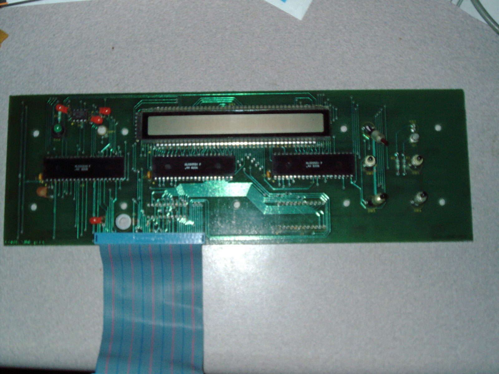
|
|
ICT-101 Brazil display board closeup ics.JPG Size : 903.396 Kb Type : JPG |
I ordered these ICs a couple of days ago. Today the seller emailed me that it is shipped. I hope my research and professional hunch is correct- about these chips being a correct replacement. $100US is alot of money to spend on 3ea chips. This seller was a reasonable seller and accepted my lower offer from $38 to $30each. This was a real bargain compared to other "unreasonably priced sellers" who sent me quotes of $600+ These chips are discontinued and the last known price was approx $15each as of about 10 years ago. I gladly paid double their value. But the Jotrin has a reasonable price and I felt the IC tester was worth it and I'm taking a gamble on my professional hunch that these replacement ICs are the correct ones. I hope so.
Jotron Electronic Limited (Very reasonable price and prompt emails etc)
HC0550-0-P-000 HUGHES DIP40 1ea $30US ea
HC0551-0-P-000 Hughes DIP40 2ea $30US ea
$10US Economy Hong Kong Shipping 2-5 weeks
Update 7/25/15
I received the 3ea ICs from Jotrin yesterday and I have not tested them. I need to purchase 3ea 40-pin low-profile IC sockets still. Here is a photo of the Jotrin items.
|
|
Jotrin 3ea ICs for ICT-101.JPG Size : 867.009 Kb Type : JPG |
Upate 9/29/19
I stayed up all night until 4:30AM fixing my #3 ICT-101 after 4 years of sitting incomplete on my worbench. I had collected all of the needed parts and other life things got in the way of this project for years.
I found my 3ea ICs for the LCD repair which I paid $100 for these parts 4 years ago and still in sealed antistatic tubes covered in mfg shrinkwrap untouched. I cut the legs off the old chips one at a time and cleaned the board and holes neatly. The nearby LCD display was covered in foam and tape to protect. I was very careful as I could not socket the ICs since the LCD was designed to fit behin metal front panel unsocked- no space for IC sockets. The whole front LCD panel assembly was a pandoras box and reassembling was VERY difficult. I read from my previous notes that I had replaced a transistor on this LCD PCB in previous years. The ribbon cable end is in bad shape and needs replace but I just recrimped with my Radio Shack IDE style ribbon cable crimping tool purchased long ago. The LCD now works but one horizontal line is extremely light and almost non-existent. Even so I consider it as the LCD is legible and before only 2 digits displayed. Is it possible that I got a weak IC chip?
I reread my own notes above to refresh my memory on what was done and even so I still opened my other two units in order to part swap the epoxy covered proprietary memory board (seems ok) and the top PCB was part swapped into other unit (seems ok) and I saw that I replaced the pins on the lower board for the epoxy coated memory module. And I see that I replaced 2 ICs and socketed previously. I think after all of the parts swapping - the three units were intermixed but I can tell that the first unit is fully socketed by me in previous years so that unit is original.
I performed Lissajous pattern testing using my Beckman Scopemate and Kikusui Oscilloscope and compared the 3ea mainboard chips one-by-one in-circuit to eliminate chips which were good and those I was not sure I socketed and replaced those ICs.
I ran into an intermittant power off/on and tapping on the unit powered up mmomentarily which I was able to tap strategically to find that it was the power supply causing this. I disassembled power supply and found the ceramic large recyangle resistor had a broken solder trace which I repaired by scraping the trace with a utility knife to bare some copper nearby an flow more soler to bridge. Now there is no more intermittant power and is stable.
I ran into "Cant Find GND" message on this Italy unit and changed out and socketed on the mainboard 1ea 7414 (near Mallory Speaker and 1ea 74144 (second one from left all in a row) and this now gives correct "Cant Find VCC" as it should be.
I have not re-tested all of my 3ea units at this time for functionality for in-circuit testing.
The Italy ICT-101 is now fully fixed as much as humanly possible I disabled the alarm tone with an internal jumper to "off" as I believe the speaker is a combo speaker and battery backup of some type "Mallory" and may have a weak internal battery. The unit apears to work with 2 minor flaws 1) LCD display show one faint horizontal line of pixels (from most angles looks like a missing horizontal line of pixels) 2) no sound or beep when a switch is pressed.
|
|
ICT-101 from Italy Done 092819.JPG Size : 913.518 Kb Type : JPG |
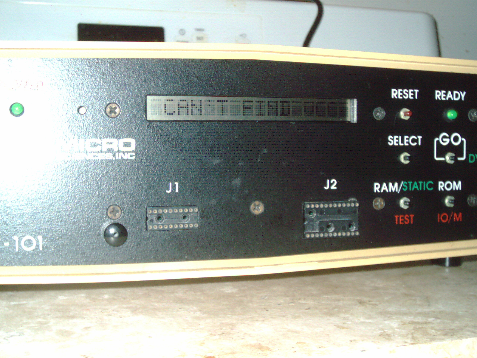
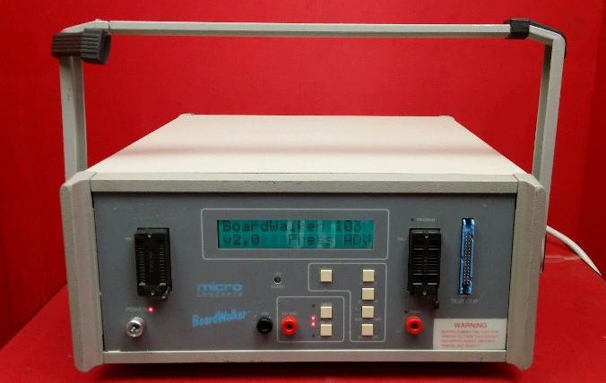
This is a digital IC tester which can test in-circuit (using lefthand zif socket on front panel) and out-of-circuit using a ribbon cable with IC clip - attached to blue connector on right side front panel "Test Clip" My unit was purchased 9/2016 used and was missing the ribbon cable and manual. This unit is model 103 and has Version 2.0 software and shows 1991 mfg year on LCD. Backlit EL (Electro Lumen) display (Blue-ish Green-ish Backlight). According to my research, I believe that this was the last revison/model of this series of testers. Im glad to have another in-circuit tester which makes my life easier when repairing damaged or non-working vintage boards - it means that I dont have to desolder the IC before testing (as often - desoldering is still required for stubborn issues with some repairs)
Very Large - about the size of a desktop PC case. Has a carry handle which serves as a "foot" when swiveled down. I repaired this unit (see my repair notes for details)
Features
In-circuit testing, out-of-circuit testing, Search function (identifies unmarked or house-branded chips), Probe Function, Logic Monitor Function
Wanted
Manual
I have not yet created a chiplist for this unit. I am able to scroll through the menu to see all of the testable ICs. I have the standard ROM built-in. I do not have the extended plug-in ROM which goes in the front panel lefthand IC socket.
Update 11/15/16
I received 5ea 34-pin IDC connectors today from international seller. I immediately got to work crimping the connector onto my existing 16-pin ribbon cable with IC Test Clip. I made the mistake of plugging in the new connector into the Boardwalkers 34-pin socket which was missing the 2ea blue side levers. After plugging it in - I pulled on it carefully from each end trying to unplug it- and the connector's snaps broke. Since I ordered 5ea, I had 4 spares - no problem. I redid the connector and shortened the cable with a pair of scissors to get rid of the marks/piercings of my previous attempt.
This time, I scavenged 2ea blue IDC connector levers from a bunch of high end equipment which I am working on (Rank Cintel ADS2) and I have alot of spare parts for. Th blue levers are not a perfect fit - a different brand of connectors - but works good enough where the levers can safely unplug the IDC connector from the socket.
I have included 4 photos "Boardwalker IC test Clip A,B,C,D"
I powered up the IC tester and went thorugh the menus but shut it down since I just dont have a manual for how to in-circuit test ICs. I didnt want to risk damage to the tester or circuit- without a manual possibly doing something wrong.
|
|
My BoardWalker 103 repair notes 100516.txt Size : 16.469 Kb Type : txt |
|
|
BoardWalker103 Passed Loose Pic A.JPG Size : 767.643 Kb Type : JPG |
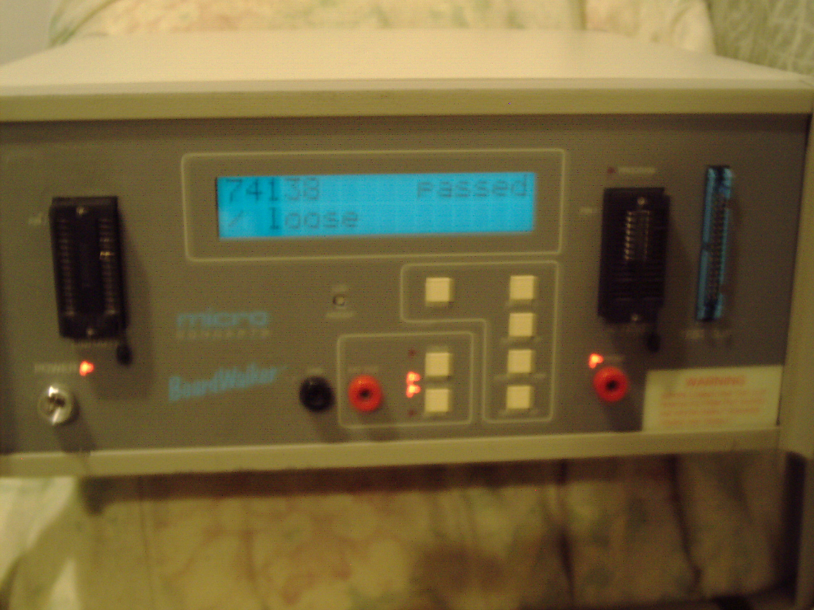
|
|
BoardWalker103 Passed Loose Pic B.JPG Size : 882.723 Kb Type : JPG |
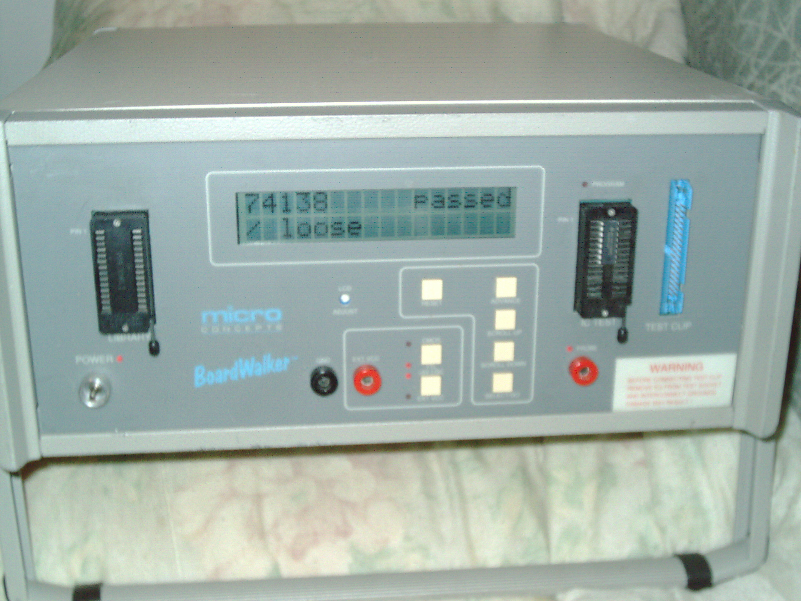
|
|
Factory wrong assembled (left) and Jerry-Rigged Loop-de-loop fix (right) test Clip w ribbon cable 092916.JPG Size : 939.585 Kb Type : JPG |
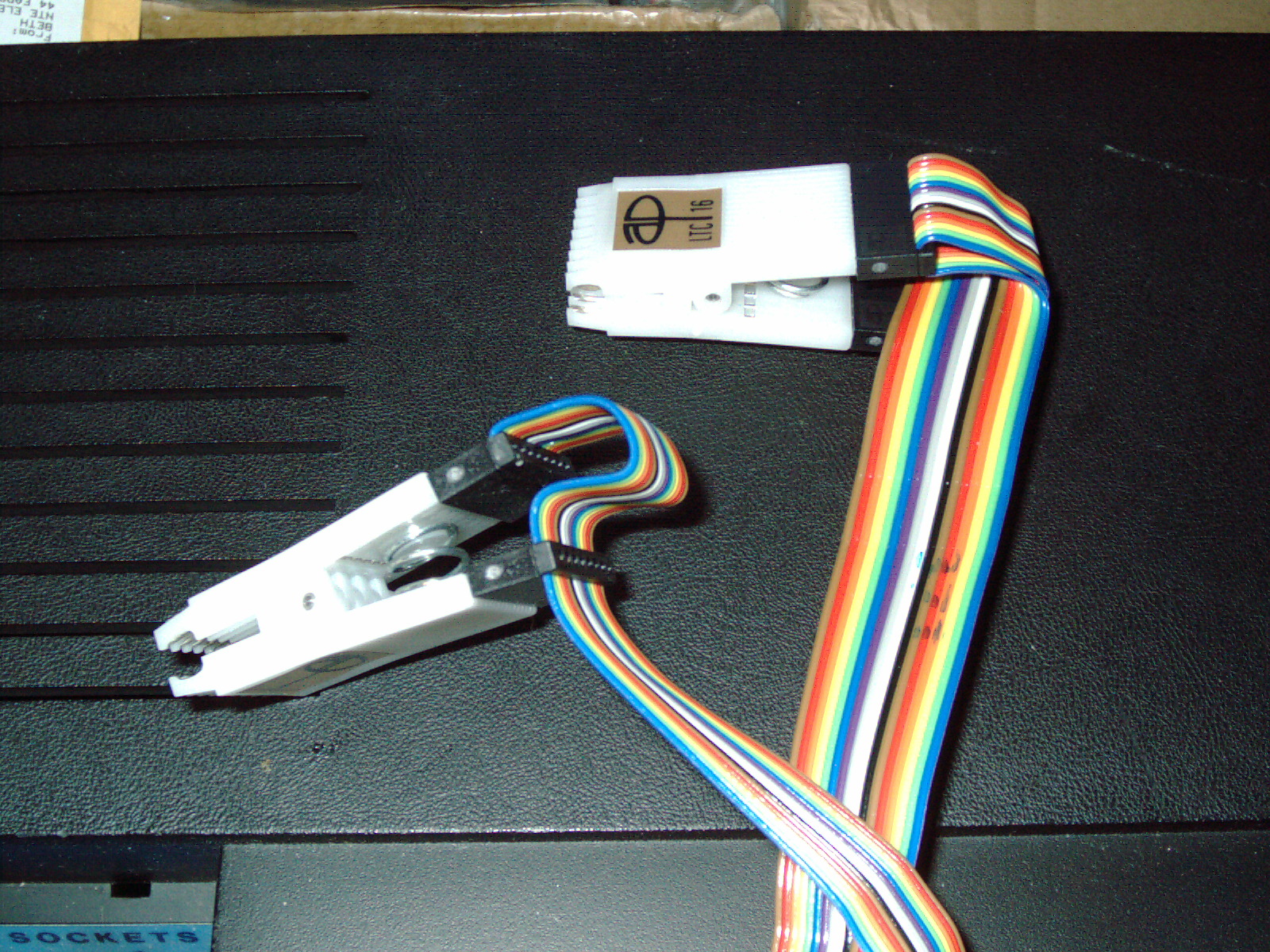
|
|
Boardwalker repair - Found unrelated small piece rattling around inside 092716.JPG Size : 841.474 Kb Type : JPG |
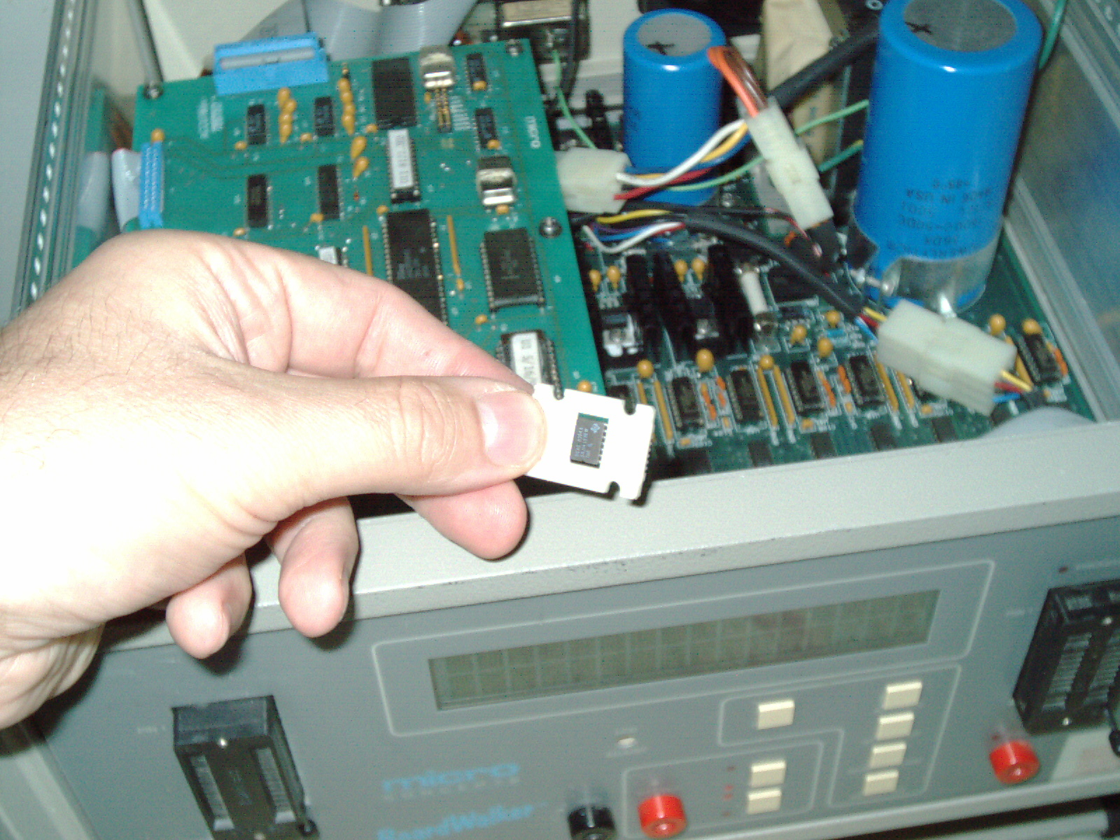
|
|
BoardWalker Error Scrolling Message 092716.JPG Size : 816.91 Kb Type : JPG |
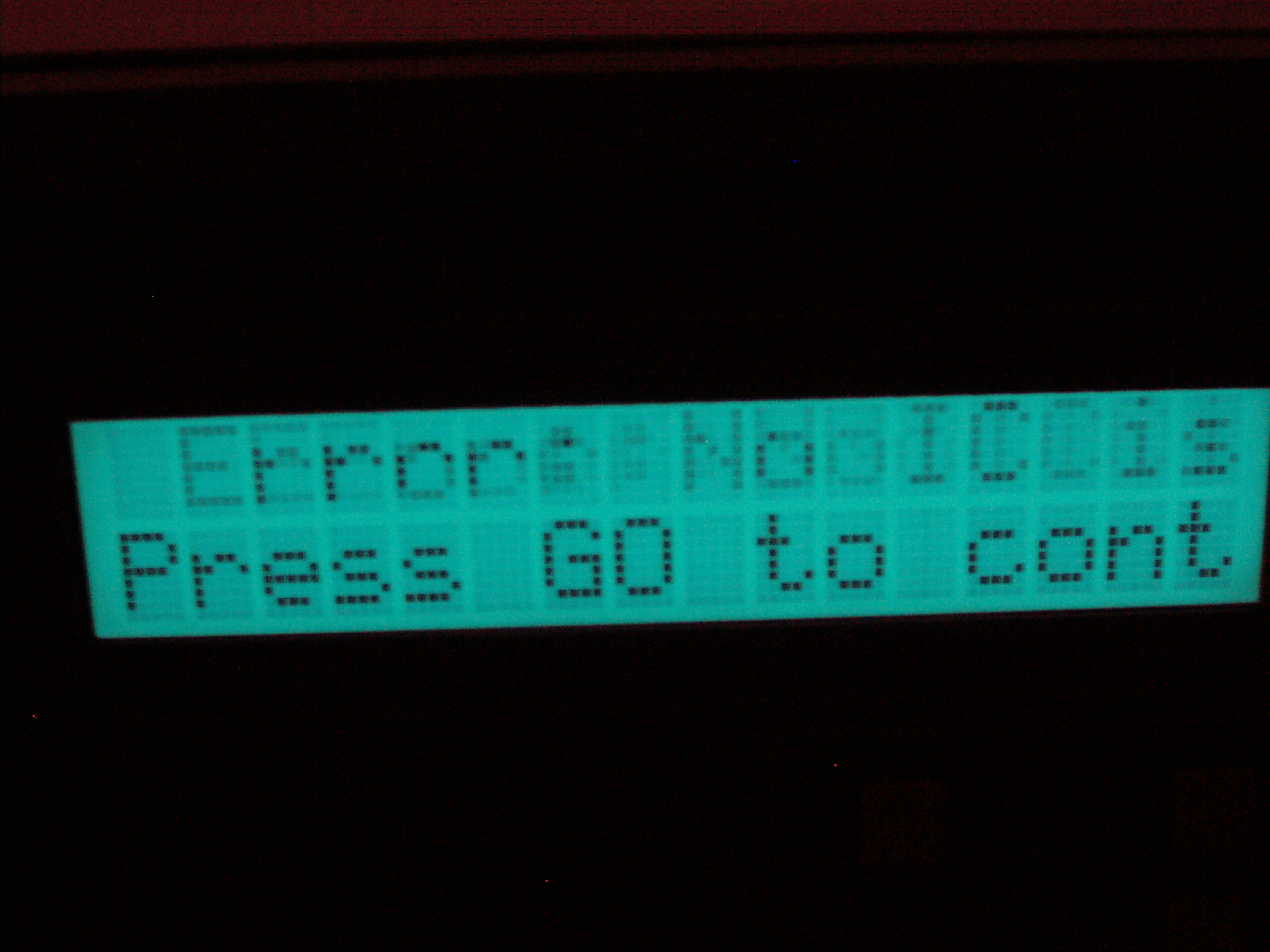
|
|
Brand New Factory Sealed IC Test Clip Package (contained incorrectly made) 092916.JPG Size : 892.211 Kb Type : JPG |
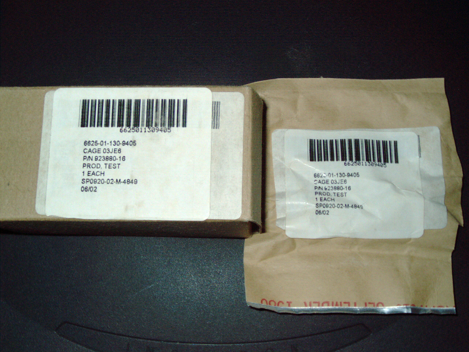
|
|
Boardwalker Test Clip A.JPG Size : 819.221 Kb Type : JPG |
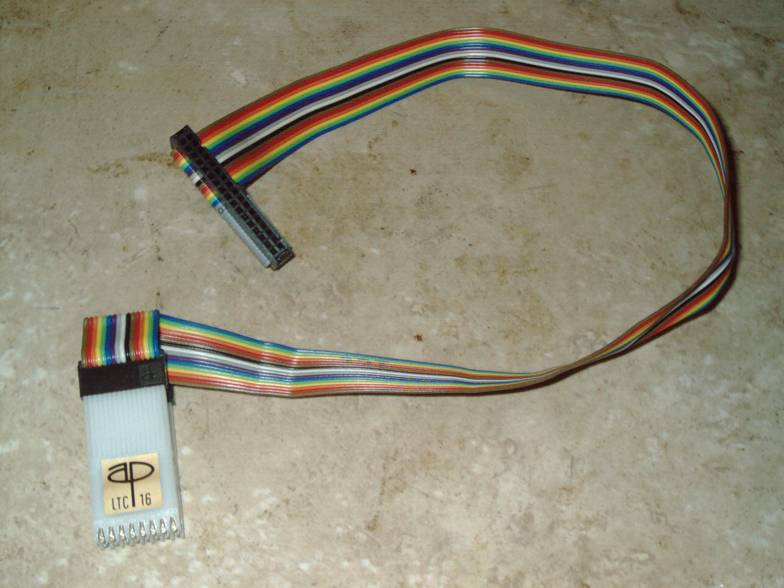
|
|
Boardwalker Test Clip B.JPG Size : 802.81 Kb Type : JPG |
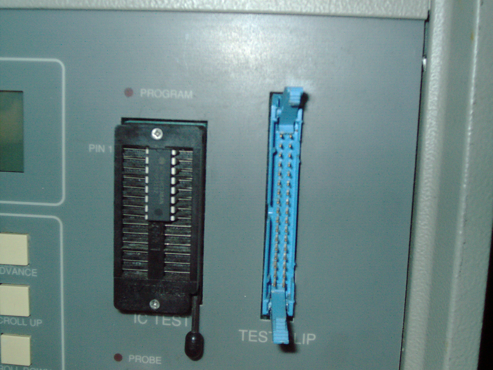
|
|
Boardwalker Test Clip C.JPG Size : 796.882 Kb Type : JPG |
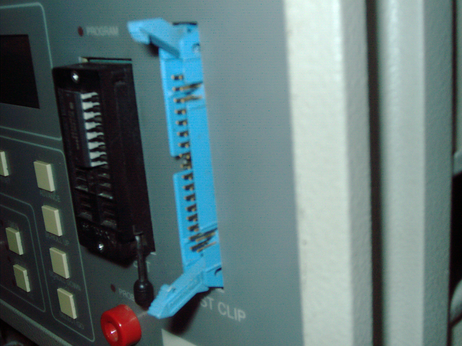
|
|
Boardwalker Test Clip D.JPG Size : 844.606 Kb Type : JPG |
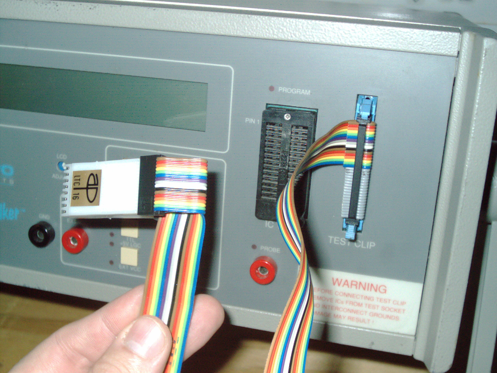
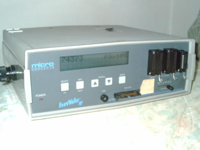
TTL digital IC tester for use with out-of-circuit and in-circuit testing.
Purchased used 4/24/17 from online seller auction site in untested condition. The date of Mfg estimated 1987 (manual date 1987). The case is grey and front panel and rear panel are a darker grey color. Buttons on the front are membrane style (like a microwave oven) The LCD is 16 characters x 2 rows dot matrix style letters and numbers- with no backlight. It came with quite a few test clip ribbon cables - only one of which looks original. Im glad to have the multitude of 24-pin, 40-pin, 20-pin cables - some of which have IDC connector and others have DIP IC style connector. Some have shrink tube attachment of IC test clip. Possibly some of these cables were made by the previous owner. Included was the original manual (about 3/4" thick) and a white AC cable with a right angle PC style detachable power cord (not sure if that is the original power cord but works good)
Missing one square rubber foot (I may have one just like it in my inventory- it looks like alot of contact cement was applied - may have been attempted to fix by the previous owner?) and missing swivel handle/stand - the 2ea attachment points for this handle are present. The box had a rough journey and very very low amount of styrofoam (only 2 pieces) so the tester arrived with broken 26-pin (13-pin x 2 rows) IDC connector on the units face (I will replace it at some point in the future) and most of the test clip cables arrived with bent pins (will try to carefully straighten without breaking off the pins)
ROM version is 2.0 (probably the latest version for this model) and I successfully tested one 74373 IC (pin one is facing up when inserted into IC socket) which completely covers the right-most IC socket (this socket is for skinny ICs up to 20-pins) I was amazed that it powered up and gave a normal looking LCD display (how many times have I received a used item and it worked fine?). There is no backlight. I skimmed through the manual and it said that the Pin Selector Switch is required before testing an IC. I scrolled through the chiplist (Long List) and found 74373 and moved the VERY LOOSE almost broken Pin Selector Switch to 20-pin setting. Then I pressed GO - didnt work (said no ground detected) and I tried the select button and got more errors "VCC and GND dont match"
I made the correct assumption that the loose wiggly pin-selector slide switch was the culprit. I pushed it in slightly and then proceeded to test properly. "74373 PASSED" and I photographed it (see photo)
So the basic function of the tester is in working condition- but pin-selector switch is in bad shape.
The BEST feature of this tester which is In-Circuit IC testing ( some people call it "backdriving" ) has not been tested yet.
As I have an opportunity to read the manual and improve the loose/wiggly pin-selector switch and other repairs, I will update this description.
There are 3ea IC ZIF sockets on the front panel. The left is for External Library ROM chip (I dont have that Extended ROM- the manual shows loading the software "E Z Walker" on 5-1/4" floppy diskette and PC to develop custom ROMs.) and the Middle Zero Insertion Force (ZIF) IC socket is for WIDE chips. The right-most IC socket is for narrow/skinny IC chips up to 20-pins.
It appears that when testing a loose/unsoldered IC chip the pin-selector needs to be moved to the right - to select the correct number of IC pins 14, 16, 20 ... But when testing a soldered chip mounted permanently on a PCB circuit board - then this pin selector switch needs to be moved left-most to the "OFF" position. This pin selector switch is not a power on/off switch - but it does select where the IC chip under test is located - in the zif socket or soldered onto a board and linked to the Boardwalker 101 by ribbon cable with IC test clip.
Unfortunately my pin selector switch has a drastically bad feel and wiggles and wobbles - it has a hacksaw blade feel when moving it left and right. It is possible it was damaged in shipping - its too bad that there was insufficient packing material as I paid extra and requested it and even offered to pay more etc and explained that ... Whats done is done. Now I have to focus on its repair.
I see a 25-pin connector on the backside - I dont know the purpose of that connector yet Most likely it is the way to connect to a PC using E Z Walker software (I have emailed seller to see if she has missing handle and 2ea missing diskettes)
The manual explains "Boardwalking" as a custom ROM test sequence made by the user - in which an entire board can be tested IC chip to next IC chip to next IC chip ... in the users custom sequence contained in the user created ROM. Boardwalking (to the best of my understanding after reading the manual sections) means being able to test every chip on an entire board. It further explains that the user can create a new ROM for every different board. Thus making a unique ROM for each and every unique board- this saves time in scrolling through the chiplist- and also allows custom chips to be tested that are not on the chiplist. I dont have this software to do this - but this "holy grail" description and screenshots are in the Boardwalker 101 manual. I have previously heard of this feature on other testers - and never found anything substantial to backup this online "rumor" - with other brands/models of testers. BUT HERE IN THE MANUAL for Boardwalker 101 I see that for this tester there actually WAS a way to custom make these ROMS.
The manual is one of the best Ive ever seen. Exploded view diagrams, extensive cross reference of Generic ICs, namebrand ICs, military ICs, schematics, long detailed descriptions of functions. Also a chip by chip explanation of how the machine works. This book is like an encyclopedia for the expert and sections for the novice/casual user.
Also the tester has a "logic probe function" but that term denotes one pin testing - whereas this machine has "logic monitor" (an industry standard term) that is a more fitting term as it shows all pins on an IC simultaneous. I havent tested this function yet. This tester has logic monitor function - yet understates it by referring to it as logic probe. Pen-style Logic probes can be used on a LIVE OSCILLATING CIRCUIT but the Boardwalker 101 is NOT FOR LIVE OSCILLATING CIRCUITS so Im not going to use that function or even try it. I have a normal standalone logic monitor (see photo of LM-2A elsewhere on this page) which I can use for live circuits.
Some quirks in version 2.0 ROM
The arrow up button scrolls down numerically in the internal chiplist.
(This appears to be correct as the book describes the down arrow as moving forwards in the chiplist)
The arrow down button scrolls up numerically in the internal chiplist.
(This appears to be correct as the book describes the up arrow as moving backwards in the chiplist)
The cross reference section of the book showing military, name brand, generic ICs - the manual has some similarities to the manual for the Micro Sciences ICT-101 tester. This artificially makes the chiplist longer as mfg variants of the 7400, RAM and Eprom, 4000, 9000 series chips part numbers is long - whereas the generic list of chips is much shorter without redundancies.However some mfgs make their part numbers "far out" and unrecognizeable as ordinary standard 7400 series for example. The elaborate cross reference is both redundant BUT useful in those rediculously marked yet cross-reference-able to generic standard IC.
Super great manual with nice drawings and illustrations etc. Couldnt be better. I hope when I delve deep into programming a ROM (assuming I can acquire the software) Is the manual going to leave me scratching my head or will it be thorough - we'll see.
As I compare the Micro Concepts Boardwalker model 103 to the model 101 - I see a huge size difference and the newer of the two being much larger. Also I see the same connector on the back with missing metal surround shield on the connector - so that makes me think - it is supposed to be that way. The basic LCD navigation of menu "feel" is similar- I am missing the Board Walker 103 manual so by reading the 101 manual - I may learn about the basic function of both units - possibly the custom ROM creation is the same on both units? Who knows?
As the front IDC connector arrived broken - I taped the 2ea pieces to the top of the case (see photo) so they wont get lost. It got broken as the Boardwalker 101 tumbled around during shipping in a large box with almost no packing material. Im lucky to have had as little damage- it could have arrived in much worse condition.
There is a paper sticker on the front face panel that is very worn and almost illegible - it probably warns the user to connect the clip under certain power-up sequence. I will read the manual and try to figure out what the sticker says.
There is some damage to rightmost ZIF socket where it looks like a soldering iron was touched on the plastic. This test socket still moves well and tests IC well. I will leave it alone. "If it aint broken dont fix it."
The case is exactly the same dimensions as the MSI ICT-101 and I received emails from a software engineer who worked at both companies and was told that there were people who worked at both firms. This explains the similarities between units.
Let me know if you have a replacement multi-position slide switch for this (off plus 6 additional detent/click positions so that means 7 total detents slide switch). I have the little black cap that goes over the little switch's lever.
Clear plastic tape Sticker #1 Reads IN UPPER CASE BLUE LETTERS
"CAUTION: IN CIRCUIT TESTING REQUIRES UUT POWERED ON, +5V MAX, AND LOGIC GROUNDS INTERCONNECTED"
White square paper with red letters Sticker #2 Reads
"WARNING! Before connecting test clip, remove all ICs from front panel and place pin select switch to off position. Damage may result."
Version 101A is special
On the front panel it shows model 101. But the rear panel metal plate shows model 101A.
As I read the manual, there is a section in the back for model 101A which shows "E Z Walker" or "EZ Walker" software which is used to custom progam a library ROM which can then be used on any 101 or 101A. WOW Im looking at a machine that can do this. As I contacted the seller - she threw out a box of diskettes 3 weeks ago - and she is looking to see if an old PC has this software installed.
If anyone has the "EZ Walker" software (book shows ver 1.00 but any version is fine) for any of the Boardwalker series - Let me know. It is possible that both of my units models 101 and 103 can make these custom library ROMs?????
|
|
Boardwalker 101 received 042417 Rear Panel.JPG Size : 848.406 Kb Type : JPG |
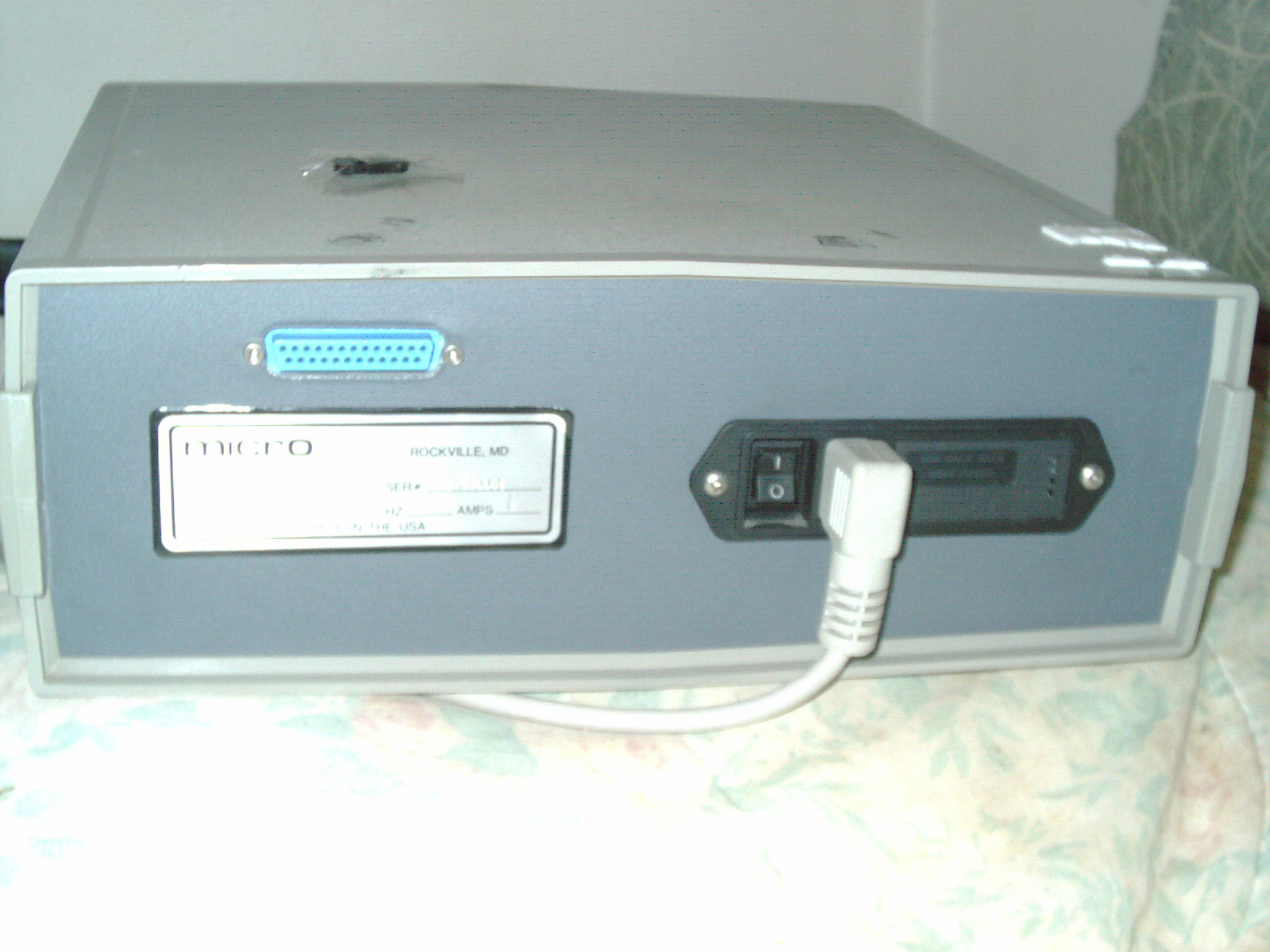
|
|
Photo of book page E Z Walker DOS software for Boardwalker 101.JPG Size : 781.387 Kb Type : JPG |
|
|
Photo of Boardwalker 101 Manual.JPG Size : 887.69 Kb Type : JPG |
|
|
A few homebrew Cables included by seller of Boardwalker 101.JPG Size : 878.3 Kb Type : JPG |
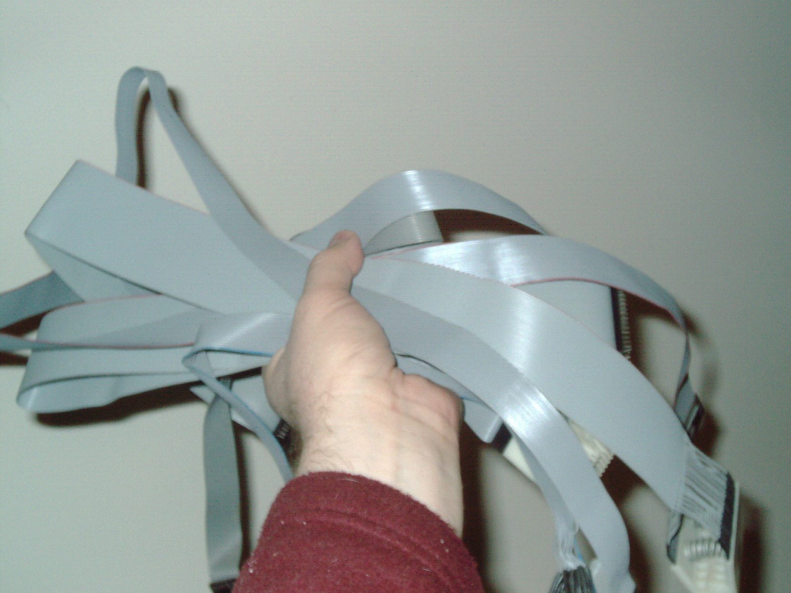
|
|
Lots of bent pins.JPG Size : 781.06 Kb Type : JPG |
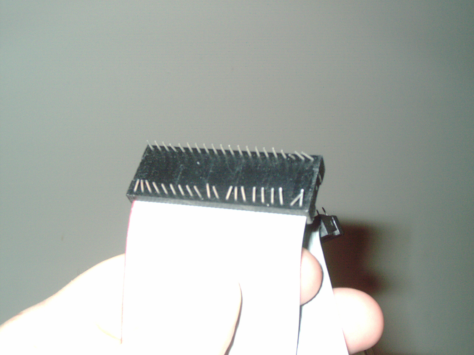
|
|
One original Boardwalker 101 cable and IC Test Clip.JPG Size : 855.015 Kb Type : JPG |
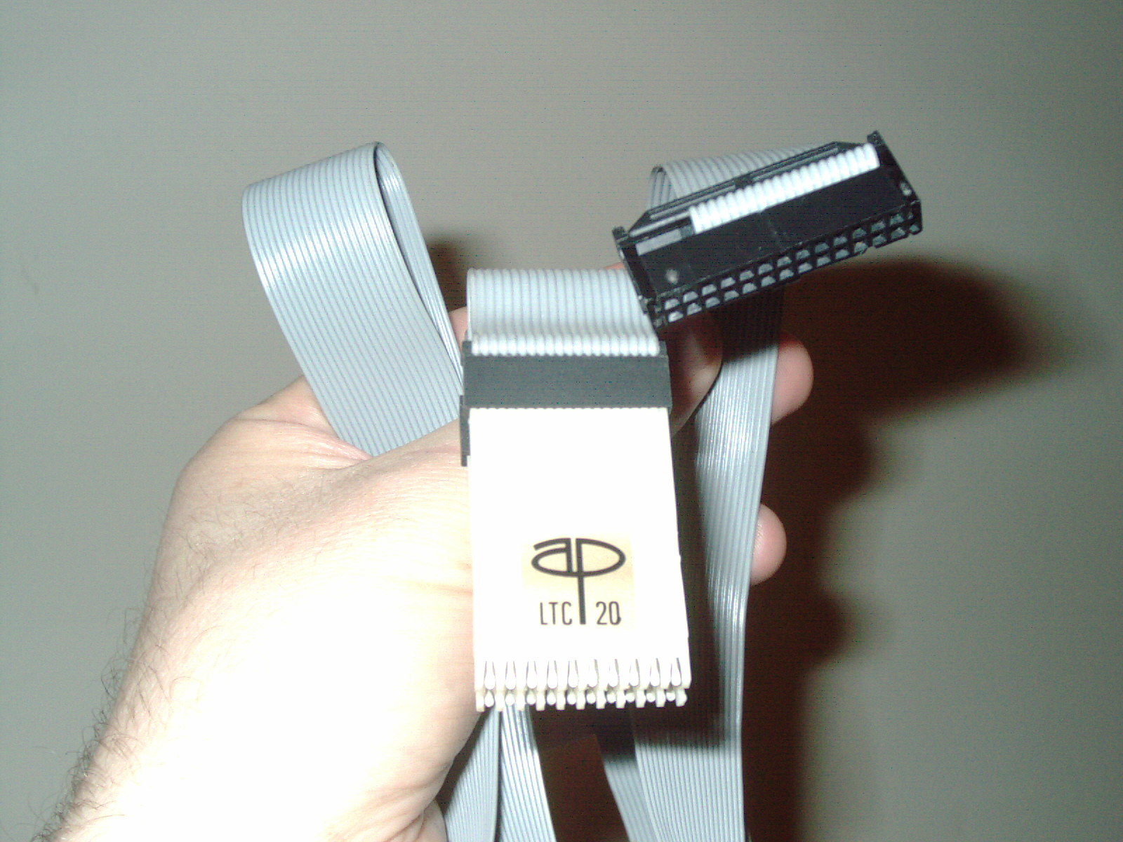
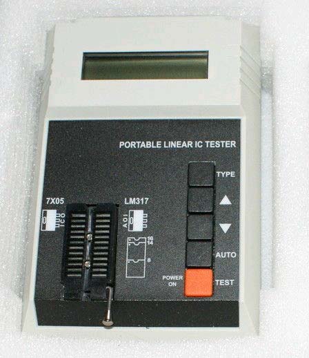
This is a Portable Linear IC Tester LIC and is a handheld tester. It is my only linear IC tester at this time and my 8th IC tester. It has the same shape and style case as another one of my testers. I'm glad to have purchased this tester as I was looking for a used one for a long time. This unit came with the original AC power adapter which is 9VDC 500ma or can run on 2ea standard 9Volt batteries. Several companies sell this tester under various name brands. I have listed the chips it can test at the bottom of this page on the right-hand side in grey color. This tester was purchased from a Canada Seller on 11/13 and shipped to USA. Purchased (New Old Stock NOS and never used by previous owner) in 2013. Manufacture date estimated 2010 (this is a currently available item as I am writing in 2013).
The label is clearly marked for chip and semiconductor orientation of inserting in the socket. The Power Off procedure is not clearly marked on the unit. Here is how to turn off unit (Hold Down "Type" button while pressing "Down Arrow" Button) I know this only because I have a "sister" unit very simiar (see GUT tester on this page above) which has it clearly marked on the label.
This tester has helped me numerous times in testing voltage regulators such as 7805 etc and ICs which are analog such as the LM series and many others. The chiplist is very strange in that you have to scroll through all of them and just in random order. They didnt even put similar semiconductors next to each other in the internal chiplist. There is alot of scrolling and hunting until you find that in the very long chiplist - but once you find it by scrolling through the chiplist - it does test the component very well. I am very careful about making sure the proper chiplist component is selected - for the correct semiconductor component to be tested. I am VERY GLAD to have it. It has saved me alot of un-necessary replacing of suspect parts.
This Tester was purchased brand new NOS from a Canada Seller in 12/2013. This is my IC Tester #8
Notes:
Update 9/07/18:
I attempted to use my Artsign JSM-40 40Watt CO2 laser engraver today (bought used from a local High school 10 years ago) to make some cuts but the machine didnt startup properly and no homing or movement from the motors. I looked inside for obvious things first like burned fuse or burned/swollen components. I noticed that 1 red LED on power supply was lit and the other one was not lit. I disconnected the power supply conector and measured voltages and found one pin without 5V. I removed the PCB and checked all capacitors and found perfection there- like brand new caps. I checked diodes and found all were good. I removed the L7805CV and tested on linear tester and see a value of 4.48V and should be 5V. I desoldered an identical voltage regulator from a known bad electronics board in my junkpile/inventory- and found a questionable L7805CV - so Im not sure which one is good bad as one reads 4.92V and when put in reverse shows 4.42V and the other one shows 4.48V one way and OV the other way. Makes no sense- so I ordered a lot of 15ea L7805CV from international for $1.50 and will wait for it to arrive. Either way one of the old regulators are bad - one or both. Hopefuly that will fix my CO2 laser engraver as it apears that the 5V was low enough where the opto device wouldnt turn on that pin to power the controller. That is my hunch and the clue was the non-lit LED. It is good to have this tester and has helped me discover quite a few bad components. When I see something flakey - like giving me a reading when I put in backwards or shows less voltage than should be- those are good signs that it is bad/weak/etc and is worthy of buying a part to be sure. I have quite a collection of scavenged parts but in this case I didnt have any already removed parts to choose from. I didnt want to put a potentially flakey voltage regulator into my laser engraver. I could have sworn I had a bunch of 5V voltage regulators but I must have used them up over the years fixing electronics for myself or for others.
Update 9/21/18
I received 10ea L7805CV in a flat antistatic tube and was a real bargain for 75cents including shipping. I fixed the laser engraver and also a project which I never could get to work (a DIY eprom programmer) and now I see why. The bad voltage regulator I borrowed from it was also bad.
This linear IC tester reads the following for a brand new L7805CV 4.98V in both directions/backwards and forwards. My bad #1 showed 0V in one direction. The bad #2 displayed 4.98V in one direction and 4.4V in the reverse direction. This linear tester has helped me repair quite a few items.
I have saved these two bad parts because they are easy to confuse as being good. Using a magic marker I wrote "BAD" on it which means a defective part. I keep confusing ICs and parts - as they are good for testing testers.
The reason my CO2 Laser Engraver 40watt didnt work is that the voltage regulator was weakened to the point where it was below the threshhold as the bad part showed 4.4V and the opto-device which it powers must have required a slightly higher voltage to turn on. This may explain why last year the laser was flickering while running on one long job I ran. It is possible that the flickering was this borderline pass/fail part which just recently crossed that line. The school that sold me this unit about 10years ago probably used it alot. I just use it occasionally. Im glad it works as I have to make some parts for a customer order.
|
|
Artsign Laser Engraver 220V Power Supply Bad 5V Regulator.zip Size : 1297.447 Kb Type : zip |
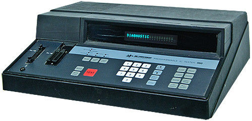
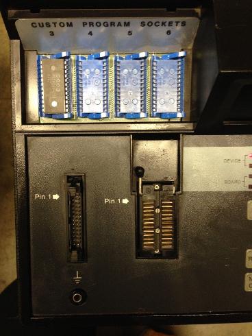
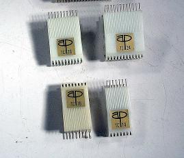
Above pictured is a B&K Precision model 560 (sometimes referred to as a BK560) Digital IC Tester. It has a 24-pin ZIF socket for inserting chips for out-of-circuit testing. It has an IDC header for connecting an external clip of various pinouts. This is my second tester which can perform out-of-circuit testing. Soldered in chips can be tested without desoldering in most cases. There are times when the chip must be de-soldered from the board before testing. Since I purchased this machine used -it came with no ribbon cable clips so I made my own set of 5ea clips 14-pin, 16-pin, 20pin, 24-pin and a 20-pin microclip for SMD chips (I see quite a few 7400 series chips which are SMD nowadays so this miniature clip is necessary to test the SMD mini IC chips of the various chip families) This tester also has the ability to learn an unknown digital chip's truth table and store that data into memory chip storage for future comparison (see 4ea empty IC ZIF sockets one of which has a data storage chip installed). The list of chips is very long and I will add this chip list in the future at the bottom of this page in turqouise color and right-hand side as my time permits. This is my 9th IC Tester. I will add a photo of my self-made clips at a later date. For in-circuit testing using the external ribbn cable clip- the circuit must be powered-on but not in-progress. By not-in-progress I mean that the circuit must not be running or operating - but it must be receiving power. To further clarify - The crystal oscillating the circuit must be disabled so that the circuit is not underway or in-progress. The crystal oscilator must be removed. For eaxample when I test diskette drives - I connect the 5-1/4" disk drive to a PC power supply but the drive itself is not connected to the controller card. This in essence removes the crystal oscillations and satisfies the requirement that the circuit under test is not in-progress. The tester tests chips which are at a standstill and are not processing any data etc. This is my second in-circuit tester and the same not-in-progress requirement is found in my other tester for in-circuit testing.
Wanted:
I am looking for the decorative plastic cover which fits over the Eprom sockets. Either a black one or white one would work. Mine is missing this cover - the factory image shows with the cover and my own photo shows without cover (purchased w/o cover)
I am searching for the rare software option for this tester. The software named "AK560" or possibly a different name - will allow a vintage PC to connect to the back of the 560 IC Tester through the RS232 serial port. The software allows creation of customized IC test program - for chips not in its internal chiplist. I wonder if anyone reading this has a floppy disk (5.25" ? 3-1/2" or CD-ROM) with this vintage software which I am seeking?
This tester was purchased from a USA Seller on 12/13. This is my IC Tester #9
Update 6/22/15
I ordered 1ea 12" x 12" x 3/32" (.093") sheet of black ABS Textured and 1ea sheet 12" x 12" x 1/16" (.060") These sheets were purchased from big-auction-site and cost was approx $15 for both including shipping. Using my laser engraver, I will do my best to make a replacement cover for this IC tester - then glue those pieces together with Weld-On #3 which is a plastic solvent and fuses the material together. I was not able to find an original replacement after years of searching. I will fabricate my own. I plan on using these sheets for several projects including making a back panel for my semiconductor analyzer/battery pack (see PST-5000 further up on this page). If I cut carefully - this material should be/may be enough for both projects. Another alternative is a 3d Printed part - I do not own one at this time (I will buy one sometime in the future when prices come down). The ABS textured sheet cut/fabricate/glue will give a more accurate glossy testured finish which more closely resembles the original.
Update 11/18/15
I drew the following 4ea illustrations (using Microsoft Paint) of making your own Test Clip Ribbon Cable for use with B&K Precision model 560 IC tester. These diagrams show the 1:1 correlation between the IDC male connector and the IC under test. For example the top 2 pins of the IDC connector correspond to the top 2 pins on the IC being tested.
Whether you choose to make a professional cable using real parts like IDC 26-pin female or ust makeshift jerry-rigged amateur wiring is up to you. I suggest making a good-looking cable that is professional looking. I purchased my IDC connector, and misc items, and my IC clips on big-auction-site.
Update 9/3/16
I purchased an original BK 560 manual from big-auction-site and posted a photo of this blue cover manual here.
Here are a few photos/drawings.
|
|
bk560 ribbon cable Schematic from IDC connector to Test IC 14-pin.TIF Size : 18.996 Kb Type : TIF |
|
|
bk560 ribbon cable Schematic from IDC connector to Test IC 16-pin.TIF Size : 19.215 Kb Type : TIF |
|
|
bk560 ribbon cable Schematic from IDC connector to Test IC 20-pin.TIF Size : 19.525 Kb Type : TIF |
|
|
bk560 ribbon cable Schematic from IDC connector to Test IC 24-pin.TIF Size : 19.936 Kb Type : TIF |
|
|
BK560 owners manual Pic.jpg Size : 267.176 Kb Type : jpg |
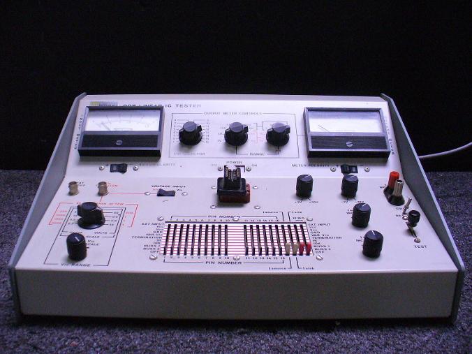
The above pictured Berkeley 998 is a Linear IC tester and is a vintage analog piece of equipment (estimated 1965 to 1975 estimated mfg year). I purchased the manual and tester from different sellers. I feel fortunate to own it as it is rare. I plan on testing op amps and voltage comparators. To be honest the manual only gives one example on how to use it and I need help on understanding how to use this tester. All of my other testers are simple to use and operate. This vintage linear IC tester is very capable machine but I need to learn and am going through the book but I can see that the book's one example is insufficient. I am also going through the internals to test components one-by-one as this is a used item purchased recently - to make sure it functions. Ideally someone will share their notebook notes on step-by-step how to test alot of chips with this tester. The title of the manual I have is "Model 998 Linear IC Tester Instruction Manual" and has schematics / parts list at the end. At the present time I am unfamiliar with how to use this tester. I look forward to using this equipment as it will tell me the linear/analog values rather than just pass/fail. This will help me assess the condition of chips so I can make the decision to replace if readout is weak.
Somethings that are not clear - use of oscilloscope in conjunction with tester? Slider sellings. Use of knobs and switches and dials. I have the 16-pin socket and the book says there are various 14, 16 pin sockets available- I would like to acquire those additional sockets.
Any help or insights on how to use are appreciated. I would like to know step-by-step how to test LM310 and LM311. I hope a kind reader will educate me on how to use this well-made machine (through email or video?). My email address is drviragopete@att.net in case a kind soul will share their insights on how to test.
It is possible there exists a manual (I dont have that) that shows settings for various chips and semiconductors. I do not have any list or settings for various ics at all - only the very thorough (only 1 example in the book) example of testing Fairchild 709 which is quite hard to follow and understand. I purchased this tester in 12/2013 from a USA seller. The testing procedure is from a different era and I am having trouble grasping the concept. It is probably very easy but I am missing these necessary insights.
This IC Tester was purchased used from a USA Seller in 12/2013. This is my IC Tester #10
Update 12/2013 I have ordered a NTE909D IC which is sealed in its original plastic bag - never used. I will use that 14-pin IC to go through the book's instructions for testing 8-pin 709 Op Amp. Due to the 14-pin rather than 8-pinout I will need to figure out which pin and slider switch needs to be used for this IC for proper testing. I noticed many other sellers of 709 chip or can package ic - the prices are skyhigh. I instead ordered this chip from RadioShack online for $3.60 w/free shipping and is a cross reference for the 709 Op Amp 14-pin edition and is a real bargain pricewise compared to sellers of other brands of 709 Op Amp. I will need to figure out the pin settings and make notes on the side of my book page - so I use the proper pinouts for the 14-pin chip.
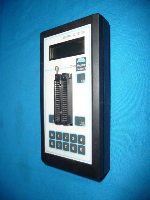
ABI Digital IC Tester Chip Master Compact
This tester was purchased used and was mfg in United Kingdom on 2005 and has ROM version 2.00 which is the most current version for this model. It runs on 6V DC at 300ma (I disagree with this voltage as I think it is not correct- I think that the TVS was either 5v or 6V as my best hunch so connecting 9v would blow it out - which is most likely what happened to the previous owner. Some chips on this board have a max rated capacitor of 6V) by using an AC Adapter (I do not have this) or with standard 4ea AA alkaline batteries. This model of tester is rebranded/branded under at least 1 other namebrand. Some models have a rs-232 port built-in which allows for user added chips and are considered the "Professional" series due to the ability for users to program their own test routines for unknown chips. My tester does not have this rs-232 port and I will use the built-in chiplist only. I see a downloadable firmware update on the ABI website for this model. I will check the firmware version and update it if needed. Hand-typed chiplist is shown in orange color on the right hand side "ChipMaster" I see some similar models advertized as being IC Tester / Identifier which refers to its ability to search for many but not all IC chips inserted in its ZIF socket. This is my IC Tester #11
I purchased this tester used 12/13 but the seller sent a non-working tester - the following files show how I got it to power up it and now works. Maybe it will help someone with a similar issue. I suggest only running this tester on batteries or its original power adapter. Do not use any ordinary AC power adapter - that is what the previous owner did and it blew out the tester. It now works well after repair. I may someday add a 5v internal voltage regulator - but for now it is un-modified except for the removal of the blown 5v or 6v bilateral/non-polarized TVS surface mount component (my best guess at what it was) which was causing a 390ohm short across the supplied power input. For now I am using it only on batteries - until I locate a replacement SMD part and possibly modify it later-on with a voltage regulator.
Update 12/15/14
I believe that fuses and TVS are both protection devices but TVS responds substantially quicker in nanoseconds rather than fraction of a second. TVS is much more INTOLERANT of too high voltages or surges or even micro second interuptions in power. When the TVS blows it is not an OPEN. It is a high resistance ( 390ohms in my case) short between the + and - Fuses are INLINE with the power. TVS is placed across the power. If a fuse blows - it opens and does not allow power to reach circuit, If TVS blows - it creates a high resisitance short - if the power source is not removed - the TVS heats up substantially getting hotter and hotter and hotter and in my case - I found a charred black board. Why didnt they use a voltage regulator such as 7905 or 7805 ? Possibly for power consumption reasons they chose to do it this way- putting the voltage regulator inside the AC power adapter rather than inside the tester? I dont have the AC adapter.
Update 12/15/14 (continued)
I caution you to NEVER connect an ordinary ac/dc adapter to this unit. It is my opinion that the part that was found to be blown on my own used unit - that part is a protection device with a very small tolerance for deviance in supplied power. It is intended to blow this part - if a non-specified power supply is connected.
Heed my advice and only use batteries. It is my hunch that should the original power supply go bad - this can also happen. Play it safe and use batteries on this tester.
|
|
How I fixed my ABI ChipMaster 010114.txt Size : 5.063 Kb Type : txt |
|
|
12300002 burned component & unattached green wire.jpg Size : 206.219 Kb Type : jpg |
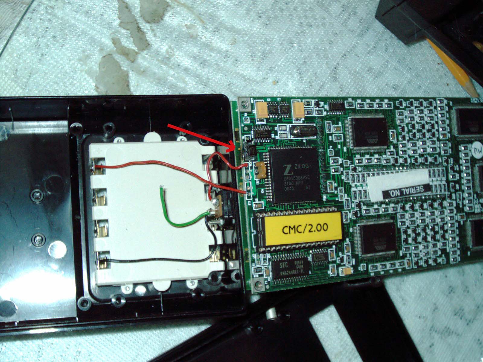
|
|
12300004.jpg Size : 149.347 Kb Type : jpg |
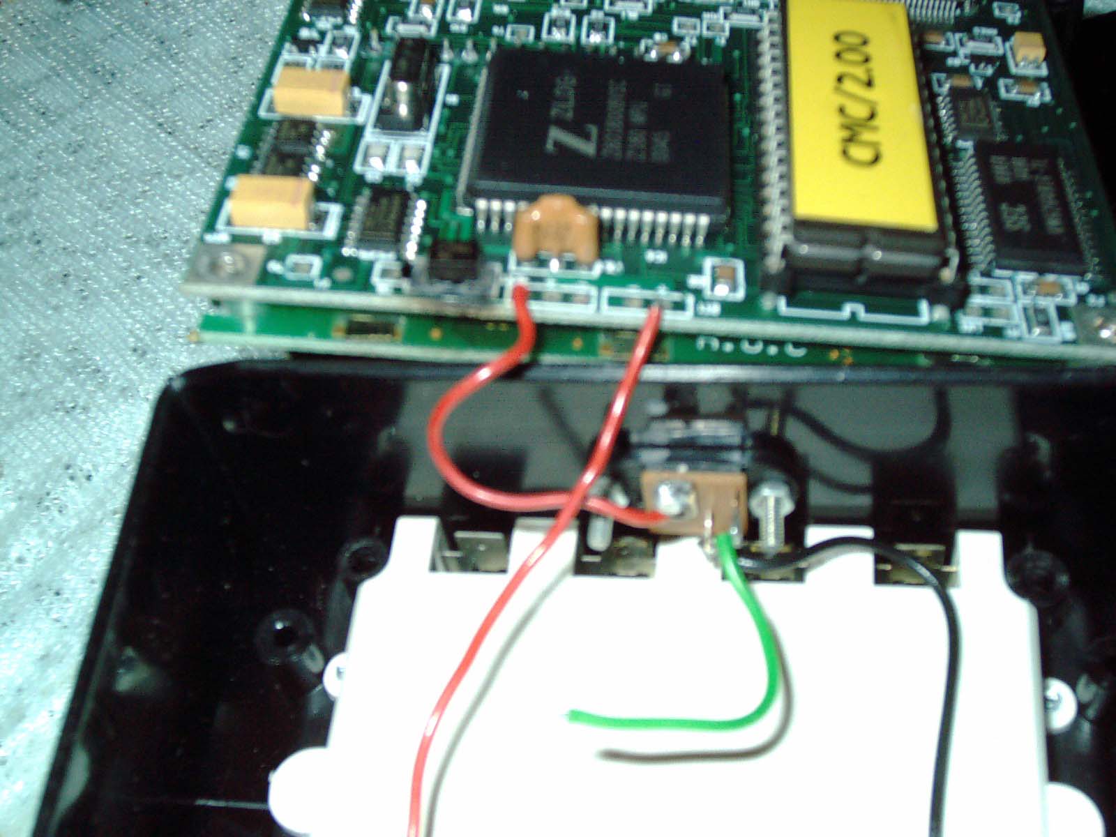
I see a video on youtube where a man is using a B&K Precision handheld IC tester (probably model 575 or 575A as my best guess) for determining whether a large quantity of Z80 chips are good. He inserts one after another after another and they all display "FAIL" on the screen. B&K Precision IC tester and ABI Chipmaster are "sister" IC testers which look similar and function alike. It is my opinion that the author of this video (not me) has entered the incorrect Z80 type into the tester - and therefore is getting "FAIL" - but in actuality - it is my hunch that this is a USER ERROR. Refer to my chiplist and notes at the bottom of this page - for example Z80 chip type can be one of the following:
Z80 Chips
Z80 CPU (Use 780)
Z80 CPU (Use 8400)
Z80 PIO (Use 8420)
Z80 CTC (Use 8430)
Z80 SIO (Use 8440)
Z80 SIO-2 (Use 8442)
Z80 DART (Use 8470)
Entering the wrong number ( I put this in parenthesis ) for example and then inserting a different type of Z80 will give a FAIL when in fact it is just user error. It is VERY possible that he has a whole bunch of BAD chips - however it may be just that the wrong number was typed in before testing these Z80s.
Search for "Z80 Tester" on youtube to see the video. It is not my video.
The technical specifications of the B&K Precision 575A (white case) and the ABI Chipmaster (black case) look to be identical in their chiplist and PDF manuals. These are "sister" testers.
--------------------------------------------------------------------------------------------
Update 4/18/15
I contacted a kind person who posted a for sale ad for 1ea Chipmaster and 1ea Linearmaster. In his ad - he mentioned that he is using an aftermarket power adapter - and he showed that both testers work. I thought to myself - that is a very risky thing to do - hooking up a power adapter when the output of aftermarket power supplies can vary substantially- and yet the used ABI chipmaster (older model verson 2.00 rom without RS-232 port) that I have - came with a burned out TVS diode - probably caused by the previous owner hooking up an aftermarket power supply and exceeding the TVS diode rating.
So I contacted the seller and asked him to take his power adapter and measure the voltage output both for the Linearmaster and also the Chipmaster.
Here is what that kind person wrote (he has the older models without the RS232 ports - just like mine)
LINEARMASTER
Power supply output without load (on air, no connection to the instrument) 13VDC maximum.
Connected with load 11 - 12 Vdc, depented on chip load (sigle test, loop....).
METEX M3610D with PC interface, 0,5% accuracy as long as I remember.
Chipmaster Tester: Output supply WITHOUT load (on air) 7VDC maximum. With load, 5 - 6 VDC. It varies depending on the load (big chips in loop, higher load in mA).
Regards,
This tells me that the testers have a wider input voltage tolerance than I expected. The TVs diode inside will allow about 1 volt overvoltage (at least possibly more but - if you put in more than that - you risk blowing out your IC tester)
Keep in mind that the person used a RMS multimeter - and since RMS meters give a slightly different reading than a regular meter- that reading may actually be just right or off a tad. I suspect that RMS was the ideal meter to use. My understanding of RMS is that it measure the peak voltage - I could be mistaken about that. SInce TVS diode respond in a nanosecond or thereabouts - showing the peak voltage is ideal because there is always ripple - no matter how clean the power supply output is.
That tells me I need to look for a TVS (surge suppressor diode in surface mount chip package SMD) diode which is 6.8V or 7V maximum in order to replace it. Otherwise I will just put in a voltage regulator such as 7806 or 7906 which regulates the power to 6.0 or 6.1 volts from experience. I appreciate the help from this person - it helped alot - I sent a couple bucks as a thankyou for taking the time to help with this matter.
Littelfuse SMAJ6.5A = 6.5V 3.3watts max
Littelfuse SMAJ7.0A = 7v unknown watts max
Littelfuse SMAJ12A = 12v unknown watts max
Littelfuse SMAJ13A =13v unknwn watts max
I searched on big-auction-site for "6.5v" or whatever voltage "TVS" "Diode" Surge" Suppressor" in various combinations. This resulted in quite a variety. According to the 300ma power requirements this would mean a 3watt TVS is needed. Many of these are listed as 400w or 500w or 600w or 1.5kw. I think that is way too high. The Littlefuse specifications are 3.3watts so that is right where it should blow - in my opinion. It seems to be a good replacement (I havent tried it- just bookwork booklearning as of now)
I looked up the specifications on TVS diodes of various brands and I havent seen any that give specifications regarding the resistance value - after it blows. My blown TVS unknown brand "FT051 BE" gives a resiatance of 390 ohms and got charred and burned the board around it -probably due to leaving it plugged in after it blew - for who knows how long?
Note I was glad to received the above measurements from the kind person. I am also amazed that the power adapter he used for each one was a switchable universal power adapter - with a selector switch to select between various voltages. It is not normal or typical to have such a tight well-controlled voltage output. Normally a run-of-the-mill average common power supply that is a wall type ac adapter (wall wart type) will vary greatly - for example a 6v DC adapter may actually output upwards of 12V ... 9V ... 7.5V they are all over the place having no internal regulation (Im not saying the voltage fluctuates). It is VERY risky for the safety of the ABI tester - to plug in a non-abi power adapter.
Update 10/29/16
Linear IC Tester BK 570 also has a TVS diode located inside. The PCB is marked SUP1 and have included a photo of this part with arrows point to it. In case a non-original power adapter is connected to it - this TVS diode will blow - instantly approx 1 nanosecond will turn itself into a resistor cutting off power and preventing damage to the rest of the circuitry.
I have purchased one of these expensive testers and I have learned from experience from ABI Chipmaster that it is VERY important to feed it correct power. Never even slightly higher.
|
|
sup1.jpg Size : 110.33 Kb Type : jpg |
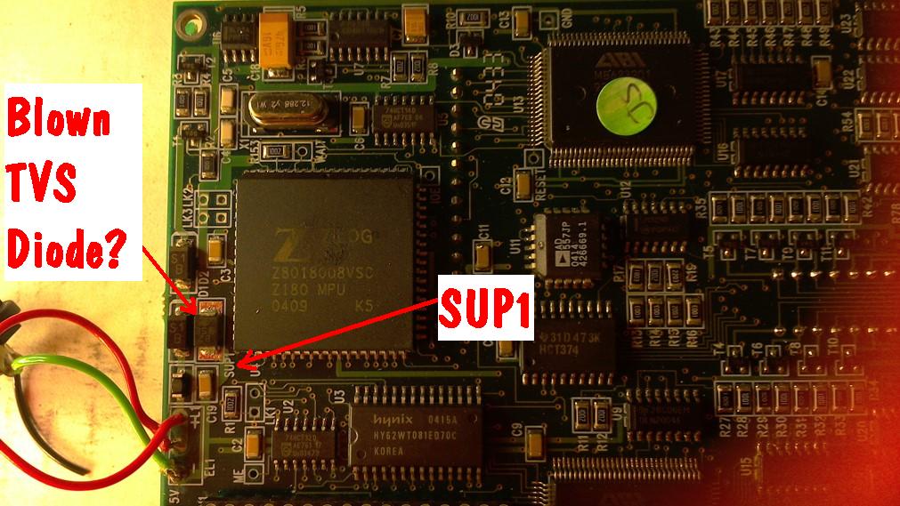
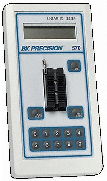
I was searching for a linear IC tester to add to my extensive chiplist. This is my third linear IC tester and glad to have acquired it. It is a very expensive unit and commands a high price new or used. As I repair/restore my Rank Cintel telecine from the 1990s and other machines/equipment etc
see my other webpage
http://www.drviragopete.com/telecine-16mm-35mm-film.php
http://www.drviragopete.com/wanted.php
... filled with thousands of socketed ICs both linear and digital and my need to check these vast quantities of ICs drives my search for more linear IC testers. The chiplist on this 570 unit is not extensive. The BK570 chiplist versus the BK575 is vastly shorter in length but one is a digital tester whereas the other is for testing analog/linear chips - so the comparison is like comparing apples and oranges - two different things. Despite its relatively much shorter list of chips that it can test - I value it greatly due to the high quality and uniqueness of the chips it can test. I really needed this unit in my daily repairs - and very glad to own it and use it. There arent that many brands of linear or analog IC testers on the market and my philosophy of "test a chip on as many testers as possible" is quite limited since I only own 3 brands/models of linear testers.
A "twin sister" tester to the BK Precision 570 is the ABI LinearMaster which is a look-a-like and functionally-equivalent (case color difference). Either model/brand is wonderful to own and use.
The Gold standard is the BK Precision and ABI - both linear and digital. Top of the line. I value ALL testers and I still continue to test all ICs in question on multiple machines. Even at the high price - it is worth every penny.
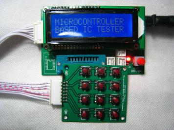
Microcontroller Based IC Tester (Caseless and purchased New Sealed from big-auction-sites)
This is my IC Tester number 12
Microcontroller Based IC Tester which has no name-brand and has no case.
This was purchased 2014 from big-auction site and was difficult to obtain because I waited too long to buy it and at that time only one seller for this item remained. It was actually cancelled by 2 sellers which I tried to purchase from. One seller from another auction website told me the reason he cancelled was that he mailed it and then it came back with reason "Failed Xray Test" which means that security would not allow it to be mailed internationally. But I finally successfully ordered it from anotgher seller (same seller who cancelled originally) and arrived - great its finally here! Very hard to purchase but worth the wait.
There were no instructions that came with this tester. The original Ad that I purchased from showed the chiplist and I have included all the information inside this Zip File which I created.
ONE very important thing which was not on the website - not printed on the circuit board - not anywhere.
The polarity of the power connector is center pin is positive +
The voltage required is 7-12volts DC. (I use a 9v standard rectangle battery)
I made myself a power cord with a 9v battery clip and then connected it by soldering and heatshrink tubing to a DC power plug which I had in my inventory. I traced the electrolytic capcitors negative - side with a continuity tester (Fluke 73 multimeter set to continuity) and I knew that whichever part of the power jack had continuity with negative-side of the electrolytic capacitors was also minus on the DC power jack.
That polarity description is nowhere to be found anywhere online - I wonder how many people blew out their IC tester by hooking up the polarity wrong? I hope not. There is no voltage regulator on the circuit board. I recommend only running it on 9v battery power.
I tests well and has a very short chiplist - I'm glad to have it.
I purchased several cases and a keyboard and 9v battery compartments etc and I will decide/modify a case to work - will update this post as I figure out/modify a case for it.
I have added the chiplist on the bottom of page lefthand side "MBICT" and is only for a short list of 7400 chip testing.
|
|
Microcontroller_Based_IC_Tester.zip Size : 1716.489 Kb Type : zip |
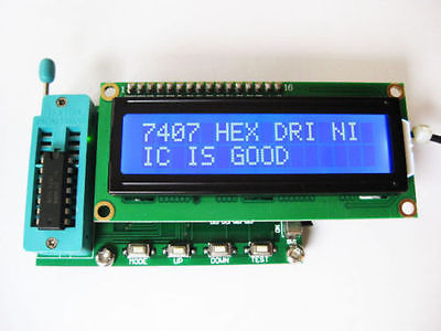
Purchased this from Hong Kong and is brand new. I jumped on purchasing this new item as it has a long chiplist and price is low. I didnt want to miss an opportunity to buy it - by waiting too long. (I am having trouble acquiring another caseless tester - which I waited too long to buy - see previous tester summary) The shipping time from Hong Kong to USA was 2 weeks. I have purchased and received several project cases and hope that this caseless tester will fit one of my project cases. Purchased from big-auction-site as a non-auction price item. It tests 7400 and 4000 and 4500 series IC chips. It is advertized as a "Logic Gate tester" and it displays the pin-by-pin status of the test progress. It ends the test progress by displaying whether the chip is Good or Bad. A nice feature is the display of the chip type/purpose for example 7407 is a Hex Driver and will display the chip's function & purpose. Buttons are labelled Mode UP Down Test. LCD is backlit. Operating voltage between 7-12 volts which allows operatiing on a standard nine volt battery.
I used a 9v battery clip soldered to a DC plug and head shrink tubing for a professional fininsh. This home-made power clip allows this tester to run off one 9v battery. I find that a standard non-backlit LCD screen (non-backlit Sharp model 1602 LCD screen which is a 16 character x 2 rows) will also run on this tester. When I fabricate a case for it - I will make it non-backlit to conserve power.
Chiplist for this tester is located at the bottom lefthand-side of this page in Blue color.
The following is a video demonstration (FLV format video) and summary of features including chiplist (text file)
|
|
TES200 Logic Gate IC Tester.flv Size : 540.572 Kb Type : flv |
|
|
TES200 IC Tester Summary.txt Size : 3.099 Kb Type : txt |
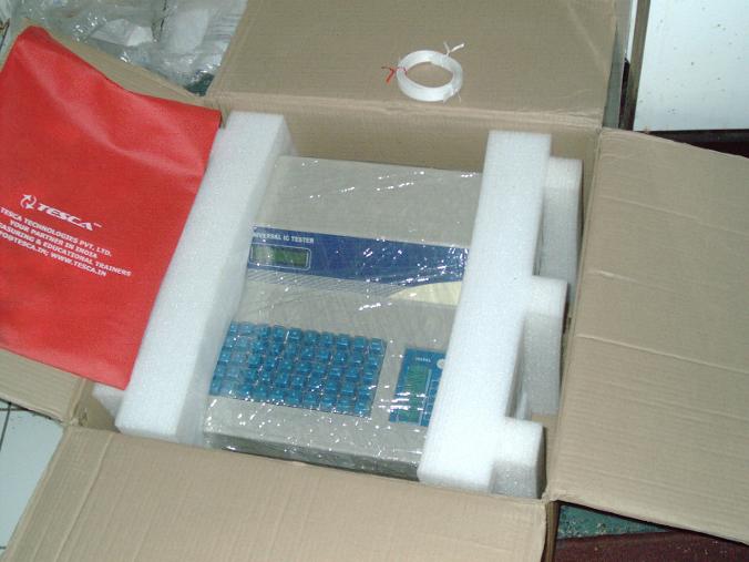
This IC tester tests a long list of common and uncommon ICs and more. It is the Holy Grail of IC testers as it has the most extensive chiplist of any tester - that I have owned so far. It doesnt test EVERY chip and there are some chips that it doesnt test. I purchased this directly from India company Tesca 9/21/16 (received 11/30/16) as a used excellent condition tester. The customs form states it as a "checking and measuring instrument" shipping alone was $143US by FEDEX 12kg weight and took approx 1 week of actual ship time to travel across the globe. The mfg wrote "DICT-03" handwritten note on the outside of box. It was packed well including shrinkwrap around tester, styrofoam inserts, plastic strapping and another layer of shrinkwrap over the box.
The main purpose in my buying this tester is to test IC chip CA3046 and LM3046 transistor arrays - which I know of no other tester which can test it. Press Mode key to choose linear testing. Then type C A 3 0 4 6 followed by press TEST key. Backlit LCD shows PASSED.
Im glad that I heard a rattling noise and opened it up - before powering up - finding 2 screws (one of which is missing threads???), 1 washer, 3 solder balls inside (see photos). I thoroughly inspected and shook out the stowaway pieces from unit and then plugged the Universal Tester into a step-up transformer 120V AC to 220V AC which I already owned. It powered up and tested every chip in my portable project case including 7400 series and ULN transistor array and of course the LM3406 chips which I carefully tested - about 20 chips total for my initial checkup that the tester works. If I just powered it up- without checking internally the rattling around metal objects would have killed this tester. I like this tester alot- Im glad I opened it up to check before powering it on.
Internally I see "Kitek DICT-03" on all of the internal PC boards. Tesca and Kitek are "sister" companies selling functionally equal units. Where Kitek seems to be the manufacturer of the internal electronics boards.
It features "Loop" test which repeatedly tests the chip and shows an incrementing counter for each time. The "find" function works and idenifies some chips which are possible matches - usually one to three are listed as potential matches. The keyboard layout is non-standard and takes awhile to locate/press the keys as the arrangement is not QWERTY style. The 16x2 LCD display is backlit and easy to read. The linear chips are tested on righthand ZIF socket; While TTL/Digital chips are tested on the lefthand ZIF socket. The "Mode" button changes between Digital testing and Linear Testing.
There apears to be some self diagnostic capabilities using the "code" key which the manual says is for internal company use - and probably gives sufficient detail enough for the mfg to determine which of the 4ea stacked PCBs separated by standoffs has a fault or not.
Owning this tester doesnt eliminate the need to own other brands & models of ic testers. However, if I had to pick one that does the most - this very expensive large, heavy steel cased tester (is in my opinion) the very best one - of them all - due to the vast number of chips it is capable of testing. Even so I will continue to use multiple testers on every chip- whenever possible.
There is an internal firmware glitch when testing IC chips 74133 & 74138 where good chips showed failed. All the other chips I have tested so far have been scrutinized correctly. Some of my other testers also have a few firmware errors - nothing is perfect in life and I have plenty more testers which can scrutinize these 2ea chips instead. Knowing it has some typographical error in one of its eprom chips - means that I wont use it to test 74133 or 74138 chips- but I will use it to test others chips on its extensive chiplist.
Internally the pcbs contain a high percentage of sanded down chips - rendering repair of a dead unit almost impossible. I have another handheld IC tester with internal Kitek boards where the chips are sanded down also. There are a few socketed chips and sometimes mfg will socket chips which are most likely to fail first and solder chips which are not likely to fail. The main cpu is Z80 processor. There are several socketed chips which are secured in place by hotmelt glue- probably to make sure they dont come loose during shipping. The tester has a very robust feel and apearance. There is very little plastic and a vast majority is steel sheetmetal TIG welded together (very nicely welded) and painted with a textured beige finish.
I have added this chiplist at the bottom of this page on the right hand side in blue color.
This was a very expensive unit (even with the huge discount from buying the mfg's demo unit- which I appreciate the reply to my emailed inquiry regarding buying a demo unit) and Im glad it arrived and worked great. If I didnt tell you it was a demo unit - you'd never know it from looking at it. It even smells new.
I was pleasantly surprised when I received this box - I was expecting a plastic shell unit (I bought from online photos and spec sheet information). Instead it has a steel case, and I like its robust heavy feel. It feels very industrial and solid. What Im trying to say is - it surpasses my expectations - in some ways.
For a school or business - having a big tabletop unit rather than a calculator size - is an advantage - as it is less likely to disapear or walk-off on its own (you know - small items are more likely to end up in someones pocket or backpack) A steel case can be chained down or secured to a table better than plastic.
It looks like a store cash register.
Tesca is located near a university in India (I have never bee there). They sell electronic training equipment for students. Im pleased with my tester and the loose screws etc inside - are probably a fluke / accident. Nevertheless Im pleased with my purchase. I recommend it. Finding the Tesca building on Google maps during the long wait - helped reassure me that it was a legitimate seller. When it arrived I was very pleased/relieved.
Cherry Electronics is located just a short distance from me. The "Cherry keys keypad" was probably made here in Illinois.
Here is a youtube video demo of the Kitek DICT-03 sister unit (Im not affiliated with this video - it is not my video)
My own unit does not say "Kitek Tech..." on the LCD - however the boards inside are "Kitek"
https://www.youtube.com/watch?v=SXatsPLxBsg
Update 12/5/16
I contacted the seller inquiring about purchasing 125V internal power supply for this unit since I have been running on 125V to 220V step up transformer (my own) and the internal power supply board states "220V IN" I received a courteous reply from seller that the "SMPS runs on 110VAC to 230VAC" So I have connected a standard USA PC power cord and runs just fine on standard 125V AC power. I no longer need to use my step-up transformer.
Update 12/10/16
I emailed the seller requesting sale of service manual, and information on using the "CODE" button for self diagnostics, parts list for sanded down chips etc. I inquired for the price of any of this service documentation - no response from seller. I tried twice. No service/repair information was available. Chips are sanded down - making a future repair impossible.
|
|
Tesca 68029 Running on standard USA 125VAC.JPG Size : 900.461 Kb Type : JPG |
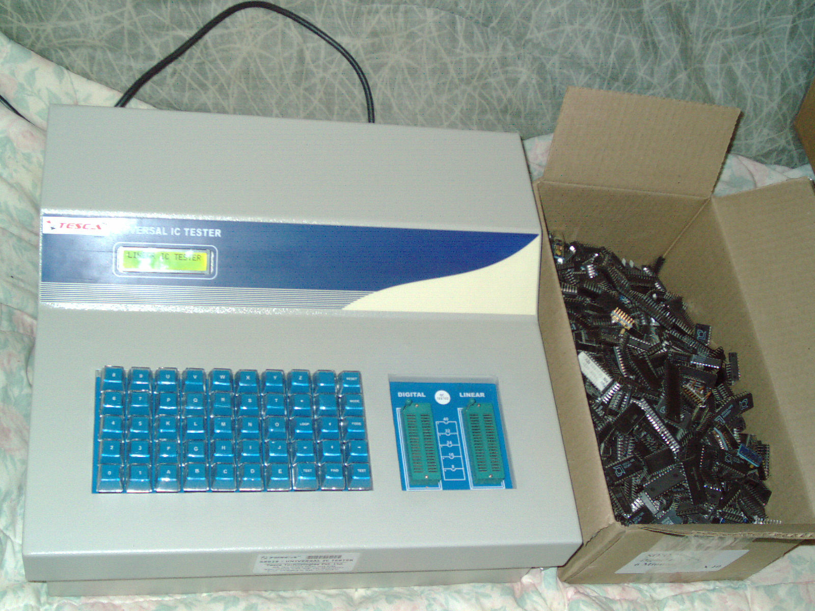
|
|
My Tesca Tester 68029.zip Size : 9283.977 Kb Type : zip |
|
|
My Tesca Tester Pics 2.zip Size : 14506.757 Kb Type : zip |
|
|
My Tesca Tester Pics 3.zip Size : 13930.568 Kb Type : zip |
|
|
My Tesca Tester Pics 4.zip Size : 11074.324 Kb Type : zip |
|
|
Tesca Specification Sheet 68029.pdf Size : 32.213 Kb Type : pdf |
|
|
Kitek DICT-03 specifications Sheet.pdf Size : 244.249 Kb Type : pdf |
This is one of the personal ongoing projects I used my equipment listed on this page for.
I have a dedication for the Rank Cintel ADS2 telecine and for my test equipment- very similar to the dedication some antique cars are lovingly restored back to showroom condition. That type of dedication - is rare and not everyone would put that kind of time, effort, financial expense into restoring something.
For this Rank Cintel ADS2 - Im the ONLY one in the world who saved this model/machine. In my opinion - it is the most complicated, most advanced features digital 16mm/35mm telecine ever created. I want to fully restore it, and Im making progress. It has come a long way. Im proud that it actually DOES something that is Demonstratable and powers up etc. Even though it is not done - needs more troubleshooting.
Luckily the mfg socketed all of the thousands of ICs in this machine. It is 2ea 19" racks full of boards each one with over 100ea socketed chips. There are several thousands of ICs, countless transistors, capacitors, diodes, switches on these boards. There are motors, multiples power supplies, lights, lamps, cooling fans, etc. The unit is comprised of 2ea full size 950lbs each estimated 19" racks interconnected with several ribbon cables and more. It requires 2ea 120V 20amp electrical sockets to run.
When TV stations/Cinema/movie industry companies had issues - the technicians service call was commonly $5,000 to $10,000+ per visit and the technician was flown to perform onsite repairs. This was a decade before I owned this machine. The philosophy of some technicians (not all) was "OH I can adjust it" and $5000 -$10000 later - yeah the machine worked, but what was needed was to replace a bad part/parts. Over time this repeated adjusting it way back to health - just is not the answer.
For example -
the bias of a weak transistor can be changed- this jerry-rig allowing the transistor to turn on and function some more - But that isnt the correct fix. After years of this tweaking - the transistor is too weak to adjust the Bias any further. Some ICs in this machine are transistor arrays - which means there are 5ea transistors inside an IC package. I feel that most of my issues are due to this and also connections - as there are thousands of cards/cardslot pins, and cable connections and solder joints etc which all need to be inspected/reseated/etc.
One seller who I bought parts from paid a guy $1500 to adjust his unit and end-of-life for that machine was when it could no longer be adjusted/tweaked jerry-rigged to work. I saved most of those boards/parts and Im going through those replacing chips/parts/components. Adjusting like that - is not how to do things. There is a time to replace parts -some of the previous owners of my parts/pieces remnants were "adjusters and tweakers" and Im undoing all of their monkey-business jerry-rigging - making it pristine again.
What I bought was the 75% remains of a unit and parts and pieces - reassembled and work-in-progress-repaired by me. The books and service manuals are extensive but component-by-component checkup is required at this time. Im very glad when I find a BAD part- because that is one more function that will work - when I replace it.
For this behemoth of a machine - the previous owners ran out of room and time for it. And I saved it from destruction - but at the same time they wanted alot of money. This inigma of "high price" versus "Seller is going to dispose of it" is quite an inigma/strange/etc. There are no words to describe the extreme difficulty in aquiring these parts. The machine was doomed without my help- and the reader would never have known that this machine ever existed.
Just like seeing an antique car in a parade - is due to the dedication of someone restoring it - otherwise it would be a forgotten vehicle - yet we all know what an antique/vintage car looks like - you know from a parade.
I also repair and maintain other equipment besides this telecine. This is just one of several personal projects and other paid commercial work
My Homebrew Combo Tester- for Transistor Array Chips
I purchased a CA3046 Switchbox Tester from Big-Auction-Site Seller in 2013. This is a product that the seller made himself and is selling in his ad- which he lists from time to time. I was lucky to find it and is a good device. I think the seller's intention is for the user to attach it to a Analog Scope. But I use it in a different way - in combination with my trusty BK815 Parts Checker - which measures leakage and gain on transistors.
I viewed and studied the data sheets on CA3046 and LM3046 transistors and see 5ea internal transistors. The last one is in a darlington configuration. I use the switchbox to isolate one transistor at a time and then I can test it on my BK815 just as if it was an ordinary discreet component 3-pin component. By flipping the switchbox to ABCDE positions - I am selection which transistor inside the IC chip case.
I only know of 2 ways to test CA3046 and LM3046 ICs and this is one way. The other way is with a Tesca or Kitek IC tester. (Which recently I purchased one- see elsewhere on this page)
I own a Rank Cintel Telecine model ADS2 which currently has intermittant issues and I need to go through thousands of these chips to test them. I purcchased this film transfer machine knowing it was missing parts and in need of major repair. I have spent thousands of dollars in parts, test equipment etc in its restoration- which is still underway.
I have decided to show a link to my testing proceedure for LM3046 and CA3046 chips using this makeshif homebrew testing manner of isolating each transistor using a switchbox. This analog method gives gain Hfe and leakage results. The Tesca and Kitek do not show this - instead it shows Pass or Fail.
By using the Hfe and Leakage results I can sort the chips according to wellness/health/condition of the chips. Pardon the poor lighting in this video.
I had purchased several hundreds of dollars worth of Harris Chips from a Big-Auction-Site seller claiming these were brand new unused chips. Due to my ingenuity, I figured out a way to test them and found that the seller was not selling brand new chips. It is my hunch that the seller had pulled used chips from an old machine in need of repair. The TV station equipment sometimes is left on continuously for years running 30,000 to 60,000 hours and then the machine fails and is discarded. It is my hunch that old worn chips were then inserted into brand new packages and sold as new.
I returned all of the BAD chips and instead ordered from a different seller.
Im sure Harris chips and National Semiconductor chips are good when brand new. My point is the seller had attempted to deceive buyers as there are no easy/cheap way to verify the condition. I wasnt duped by this bad seller.
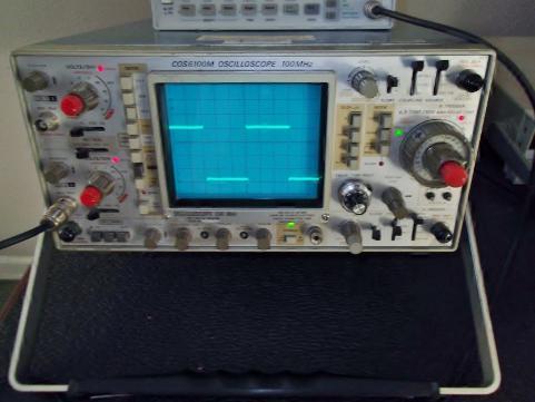
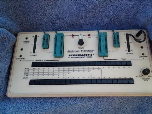
Also the latching inside of a chip may make the pin you are looking at scratch your head - why is it different this time? Well test it again - this time it displays another pattern or another pattern. My point is some pins show many different patterns depending on their internal latching state etc.
Worn chips that still work fine may differ from the brand new chip but that doesnt mean it is a bad chip. It takes experience to know what is a bad chip and what is a good chip. In summary a bad chip will have an extra swoop or squiggle or will differ in a major way from what it is supposed to look like. Nitpicking small deviation is not what this is about.
I have only shown examples of Linear ICs and standard 7400 and 4000 series patterns here (not every pattern is shown)
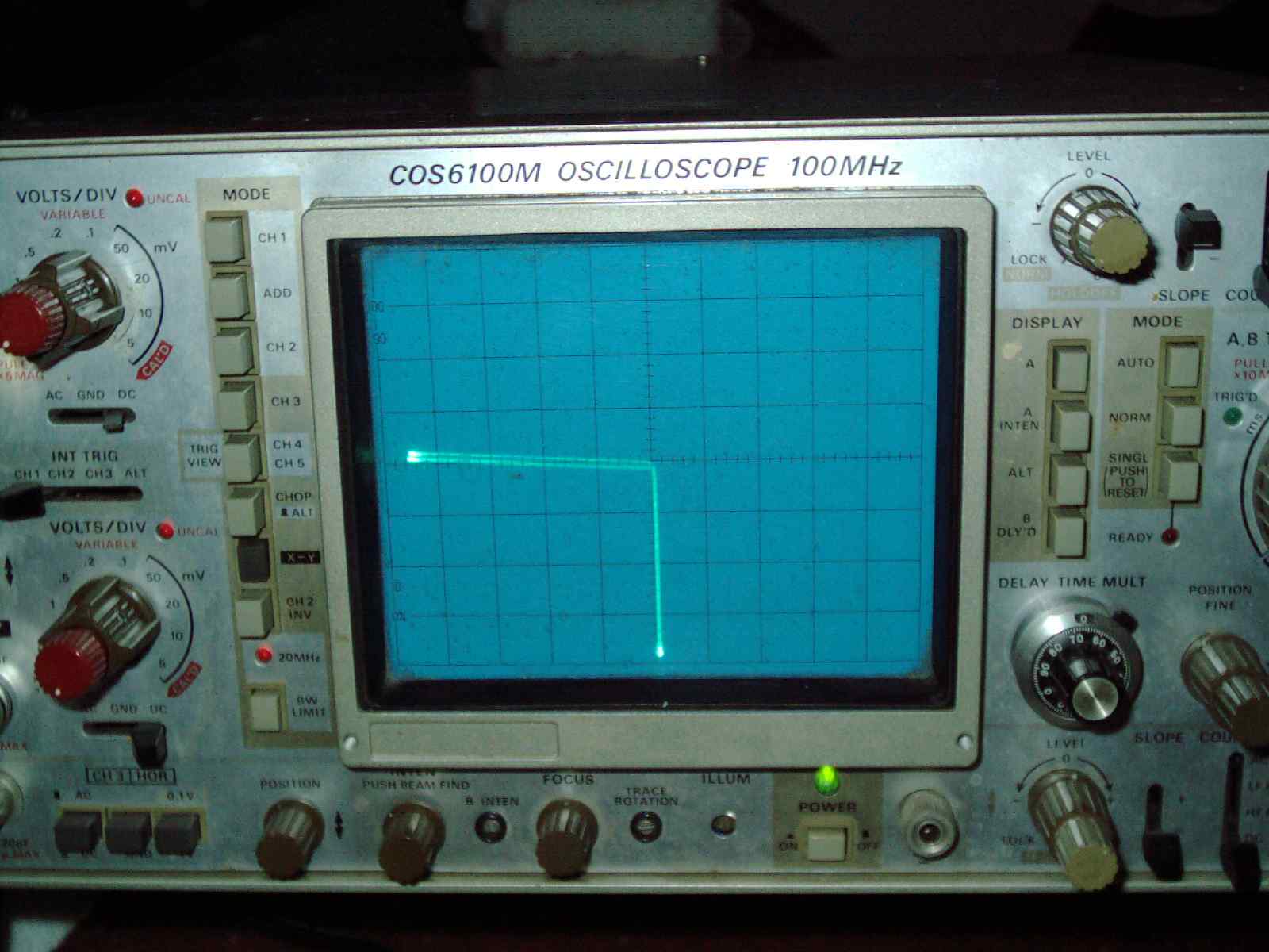
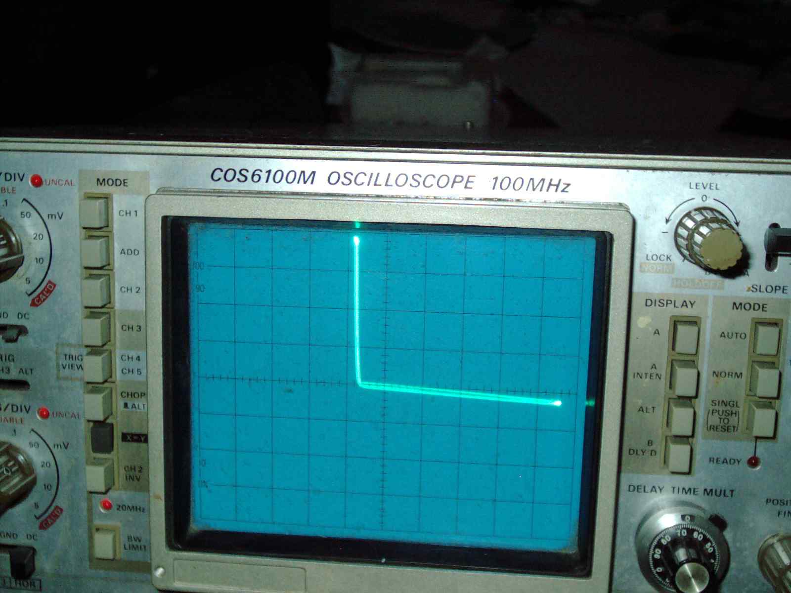
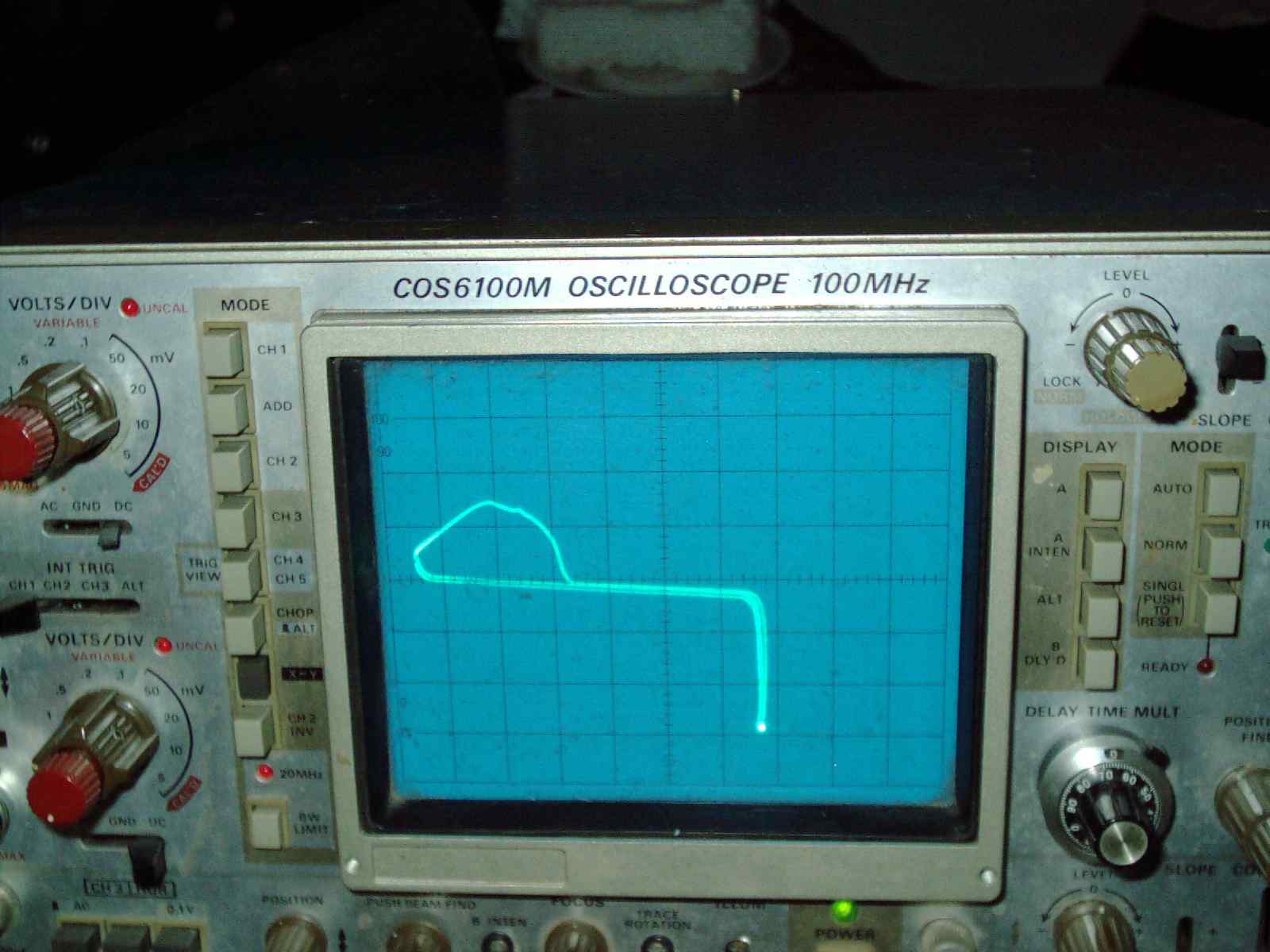
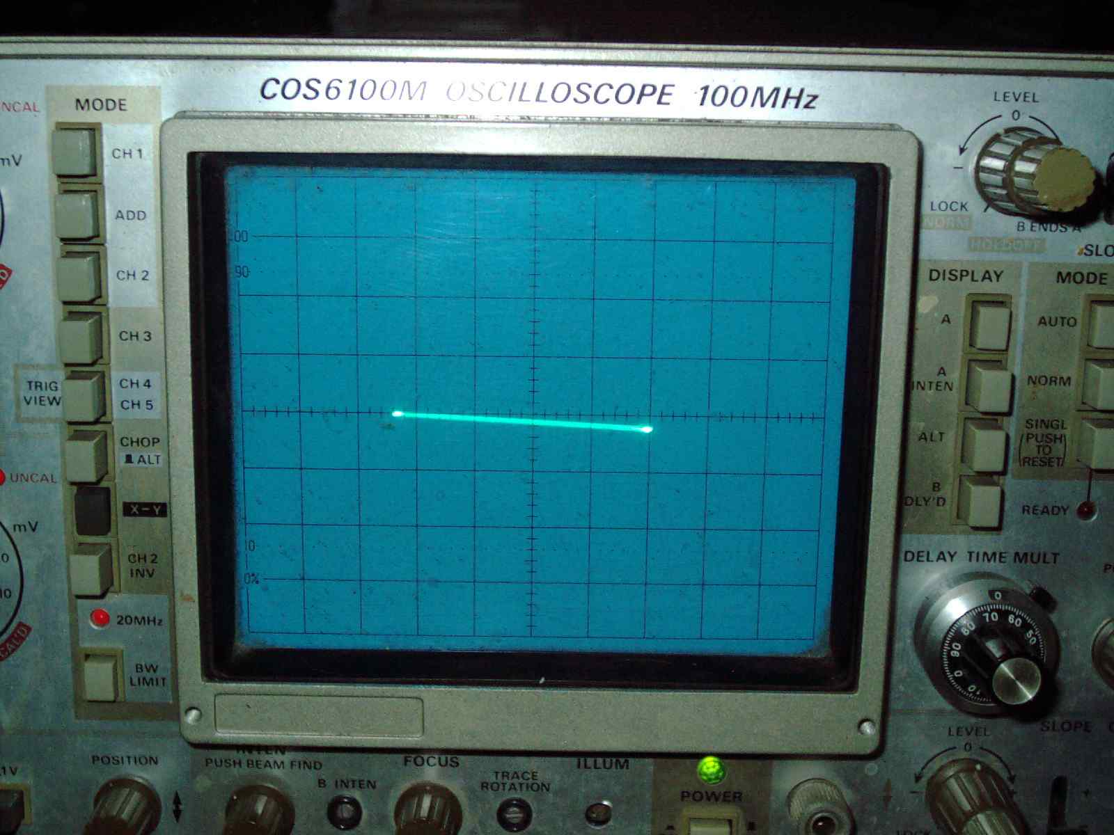
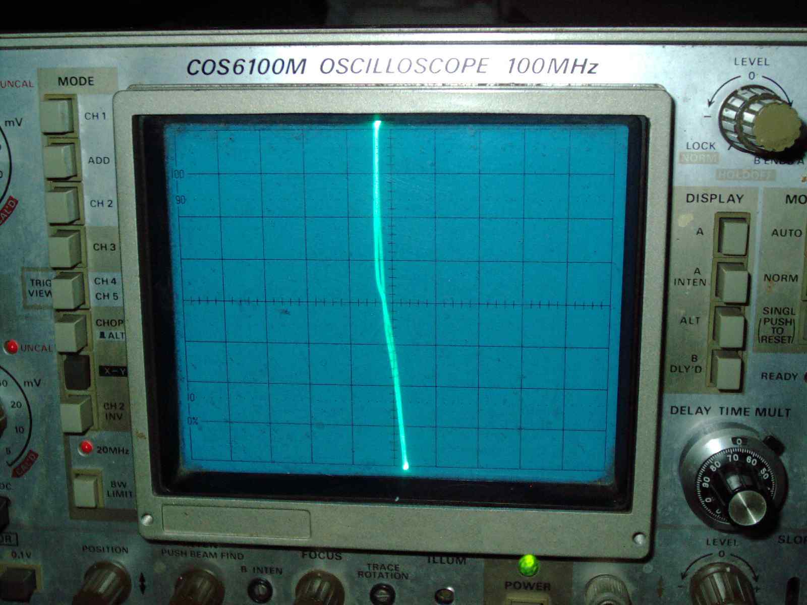
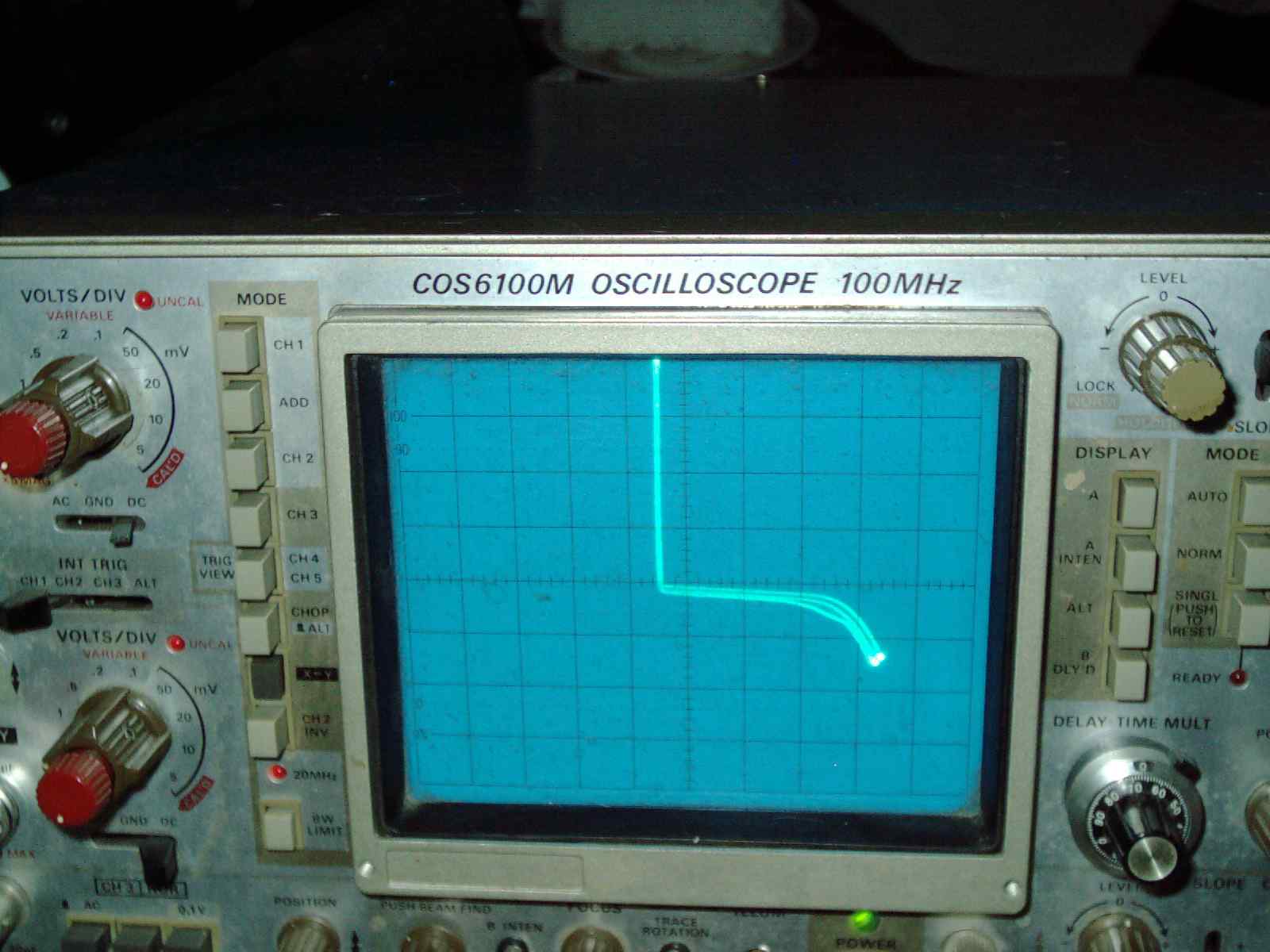
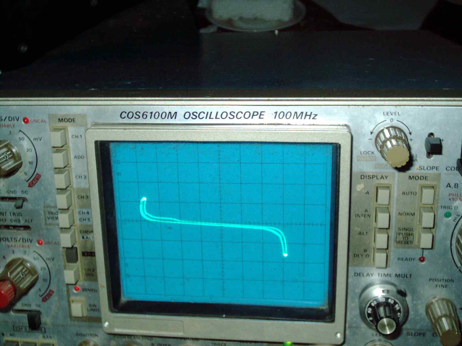
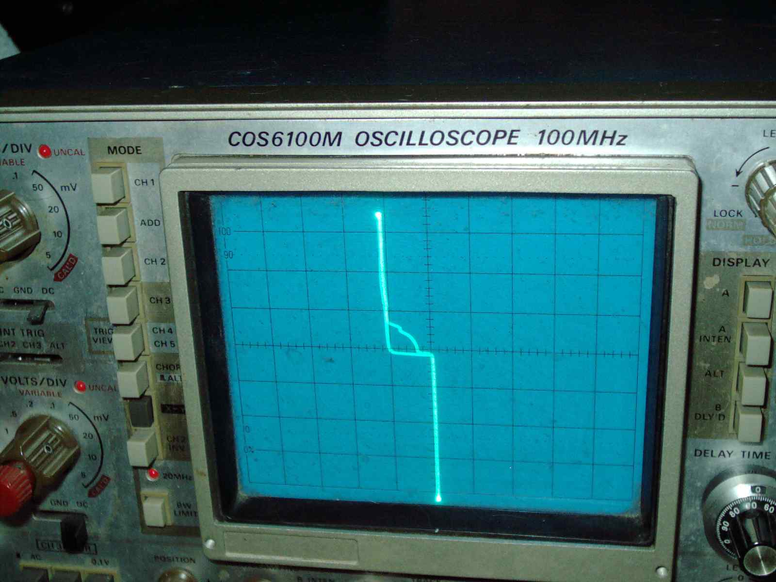
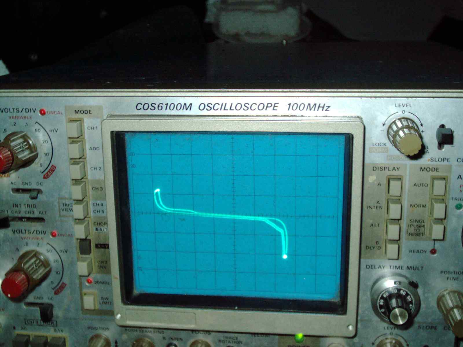
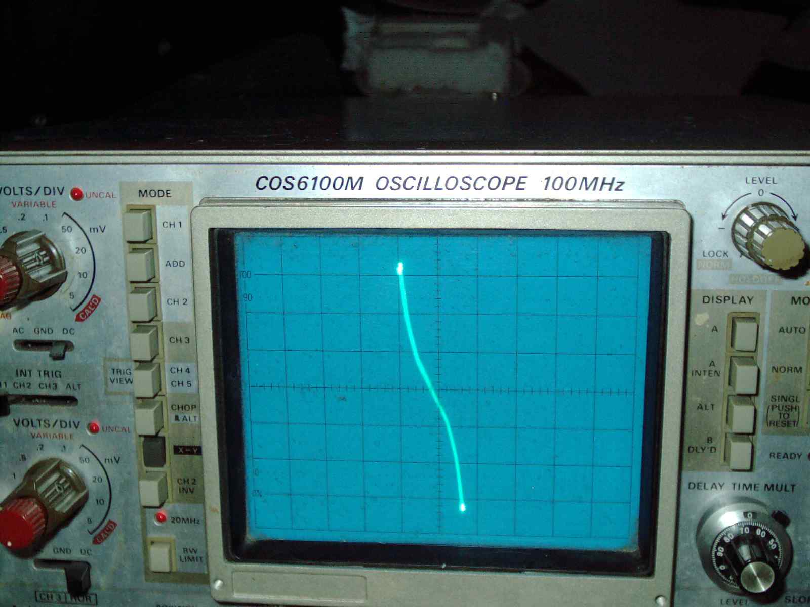
Beckman Scopemate 2 and Kikusui COS6100M 5-channel 100MHZ oscilloscope.
The Beckman Scopemate2 is described as an IC tester and component tester in the manual - but it is so much more. It tests pin-by-pin or component by component and outputs to an oscilloscope's X-Y mode to draw the pattern on screen for display. Putting a known good IC chip on one side and a questionable IC in the other side - a pin-by-pin display showing a line pattern can be used to compare whether the good part and the questionable part look the same. If these show a substantial difference - then the questionable IC is bad.
It also tests diodes, transistors, linear ICs, transistor arrays, voltage regulators and other parts. Up to 40-pin chips can be tested. This is primarily an out-of-circuit tester but by using the 2 component test probes - it gives a display similar to a Huntron. I use this setup to fix Huntrons when they are received by me for repair.
Some interesting features are alternating the display back-and-forth between known good part and questionable part. A 1-40 button press selects which pin on the IC is being viewed (see black keys on the tester). A relay click sound is heard as it toggles back between good part and questionable part being displayed. The component leads also allow comparing two side-by-side boards with automatic toggle between views or left board and right board (notice the two banana jacks on each side which is for 2 sets of component test leads) transistors and diodes etc can be inserted into the IC socket or tested via cables.
The jumper wire shown in the above picture must be set to the ground pin on the IC for each IC type. It can be used for 7400 and 4000 series chips and optocouplers etc I like it for oddball or one-of-a-kind chips where there are no specifications on the chip - but I have 2 or more boards which I can probe and compare.
The device under test receives approx 5v AC 300 microamps (less than one milliamp) which is so low that it will not harm CMOS chips.
The displayed graphics pattern is sometimes called Octopus Curve Tracer (invented in the early 1930s approx) or Lissajous Pattern or component tester. The term octpus comes from the use of a torroidial transformer and the many wires that comprise early "Octopus Curve Tracers" from that time period. Later models and designs do not incorporate use of torroidial transformer but still are referrerd to by the designation "octopus." Some new designs do incorporate a torroidial - my Beckman Scopemate 2 does not include a torroidial and is a very simple and practical circuit inside, I'm very pleased with its design and functions very well. It (and other mfgs and other designs) can still be referred to as a "Octopus" despite the fact that it contains no torroidial transformer - "octopus" is just "lingo" or a generic name for these type testers.
Some oscilloscopes have a component test feature built right in and shows the same on screen pattern- but my oscilloscope does not have that component-test feature built-in. I like my osilloscope alot and 5-channels is more than I use. The X-Y mode draws on screen - I use my X-Y mode for my Beckman Scopemate2 and it draws the represenatative pattern for each component under test. This oscilloscope is very high end in features and using it to display X-Y is a piece-of-cake for this well built oscilloscope.
The manual does not recommend this Scopemate2 for testing electrolytic capacitors or tantalum capacitors. That is ok because I use my Capanalyzer 88A for testing capacitors in-circuit and my BK815 for testing out of circuit capacitors and my DY294 tests the actual charging voltage of a capacitor. Not being able to test capacitors with this tester is ok because I am covered very well by my other testers for the testing of capacitors. I tested quite a few capacitors and some display oval and some display an oval so thin it is easy to mistake it as a line. Some parts of the manual does mention the testing of non-polarized capacitors.
Also the manual warns not to use this for testing live circuits. The testing is performed when the parts, components, ics, board etc to be tested are not powered up and all capacitors discharged. the manual also warns against prolonged cycling alternating between left and right component testing displays - it says the relay may wear out - so it is best to turn off that alternating feature when not being used.
Calibration and Manual Typo
The manual states that the Volts per division should be set to 5V (probably a misprint/typo in the manual) but this produces a very small mini Lissajous pattern on the oscilloscope screen. I find that I have a better view which more closely matches the manuals diagrams as I set my scope to 2V per division and fine tune with the red knobs for X and Y and also center the image. To calibrate - I use a brand new 2N3904 transistor and 2N3906 transistor and adjust my oscilloscope knobs and controls to match the manual's samples which shows what it should look like. Then everything lines up very similarly to the rest of the manuals samples - including the grid/graticule lines matches the images in the book.
In my opinion this is the best lissajous-pattern-type device for me since it takes up less space and does so much and applies so little current to the device under test. My oscilloscope gets used much more since I have purchased this Beckman Scopemate2 in 2014 (the tester was mfg approx 1991). The Kikusui oscilloscope I have owned for 15+ years ( purchased used approx 1998 ).
The manual was difficult to find and I was fortunate to find a seller with an extra original Beckman Scopemate2 Manual (somehow he had 2ea but one tester) which was more than I hoped for - I was expecting to only find a photocopy - but in fact I have the original manual now. I purchased this tester used and was missing cables and power adapter. I made my own cables and supplied my own powersupply (missing these when purchased). I am using a 7volt AC 300mA wall-type power adapter which I fitted/soldered with the correct plug. Usually wall type adapters supply more than their rated value and this one supplies just over 10volts as measured on my Fluke multimeter. The Voltage regulator inside the Scopemate is a 5v regulator. It runs just fine on a DIY power adapter and cables. 2 of the rubber feet were replaced due to age and deterioration (2 feet turned to sticky goo).
I see that there were 2 identical testers - one made by Wavetek and one made by Beckman Industrial. Both units look identical and bears the name Scopemate 2. I have included a photo of the sister unit as a downloadable file. My unit is the Beckman Industrial Scopemate2
I should have purchased this a long time ago.
For example I have an old power supply which I replaced in an Artiscan 8000C SCSI (Tamarack sister company scanner) scanner and I kept my old nonworking powersupply board (still have this board). I never could figure out which part was bad . Taking out all parts to test one-by-one out-of-circuit was not possible. But in the first hour of receiving this Beckman Scopemate2 & getting this tester up and running - I see that 2 transistors show only short (vertical line) on several legs - in that Tamarack/Artiscan board which baffled me a long time ago. If I had this tester back then I wouldnt have had to buy a new power supply from the mfg. It was easy to spot oddball patterns or lack of patterns for semiconductor components and ICs. Now I dont have to guess or make hunches on which components are bad - and then desolder to test. It helps reveal semiconductor condition while in-circuit on unpowered boards. Big time saver.
Case Study where it helped and didnt help
A customer brought a set of boards from a riding floor machine. He has a business where he polishes floors fro department stores early morning. His scrubber machine had an issue where the digital display on his computer board didnt function on some digits and also his raising and lowering of the attachments didnt function at all. I went through the boards with the Scopemate 2 and saw that one transistor showed a svertical line on 2 pins. There were 4 transistors alike on this board and by comparison - this transistor didnt match - so I knew it was blown. I ordered 1ea ECG287 (looked it up in my crossrefernce book) and also ordered 1ea Display driver IC chip. I compared the 2ea identical ICs on this board and found tat one had a vertical line lissajous pattern on several legs- so I knew that the display driver chip was bad. After I ordered the 1ea transistor and 1ea display driver chip - the buyer installed it and ran well for a week. His computer diagnostics onboard PCB displayed properly and also raising and lowering the attachment worked fine. He phoned me to tell me that his keyswitch was loose and he accidently shorted it against the board - the very same transistor I had replaced. That tells me why he had a blown one in the first place. So I told him to secure the keyswitch - which he did. He brought the same board to me and i went through the ENTIRE board again wit the Scopemate2 and didnt see ANY issues. I had ordered a NTE287 as a relacement for the ECG287 because the buyer himself told me that was the part that needed replaced - due to his keyswitch - he said that he even took a screwdriver and shorted the legs of the transistor and got the attachment to raise and lower. Bad buyer is poking around with a screwdriver unbelieveable! But I checked the removed ECG287 (after it was blown by keyswitch tinkering) and the brand new one and found that my Lissajous pattern for the two transistors actually was the same a - vertical zig-zag. Only when I hooked up my BK815 parts tester and ran a leakage test - did the transistor show a MAJOR difference. The brand new one shows 99HFE 000 leakage. The blown one showed 287 HFE and I leakage. I am writing "I" because it showed a vertical line - I never seen that before - it was overflow major leakage - but the transistor still amplified. Its amplification was triple what it was before. I have measured it when brand new last week and it was approx 99hfe with 000 leakage. My point is this - the Scopemate2 identified the first problem - blown transistor. but the second time I checked blown transistor - it did not see a problem. It doesnt see "leakage" in this transistor at all.
Nonetheless - it helped me in many many cases of finding bad parts. I dont just rely on one tool. I check every part on a board multiple ways - with multiple testers. I value diagnostic "second opinions" and will gladly use additional testers to check the results of any of my testers - it helps me diagnose difficult to find issues. I dont under-esteem any tester. they are all good and should be used as a team. No One tester catches everything.
I have included some photos this board which has one replaced chip and one replaced transistor (twice)
|
|
Wavetek Scopemate2.JPG Size : 128.284 Kb Type : JPG |
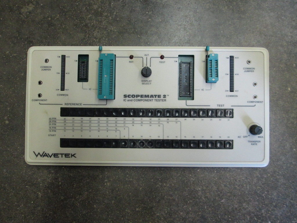
|
|
Scrubber.zip Size : 631.431 Kb Type : zip |
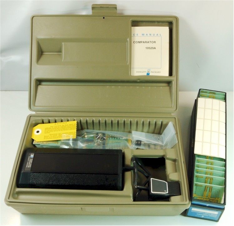
I dont yet have/own this comparator tester. But in an effort to compile information about it - I have included some examples of home-made boards which are soldered and or drilled out. I have not personally tested these board files - so dont get mad at me if it doesnt work or does damage. Maybe the person who made this board got it right or maybe not. Use this information at your own risk. I would appreciate readers photo of their own homemade boards showing frontside and backside. I would like to add a compilation of photos of these user created/modified boards.
I often buy things "backwards" for example - it makes sense to first buy an "ink cartridge" before buyng a rare printer - the point is - if you cant find the ink - then printer is pointless??? That is just an example of why I'm going about trying to find information about HP comparator cards. I want to find the information first and then when I am satisfied that I have enough information to build my own cards - then I will buy a HP comparator. Otherwise it will just sit in my closet - without the cards I need.
The HP Logic Comparator 10529A was made approx 1974 year and many people still use it to repair old electronics such as arcade cabinet units. The principle of this tester is - Custom-made IC board is connected inside the Comparator box. Then the "alligator like" IC test clip is clipped over the (test subject) IC soldered onto the live powered on mainboard of the arcade cabinet (or other machine). The one or more of the 16ea LEDs light up when there is a discrepancy or lag time between the IC to be tested and the IC within the Logic Comparator box. A custom made board must be made for each and every chip to be tested. (Also there is a universal board with dip switches)
It is important to align pin 1 on the "alligator-like clip" IC Test Clip with pin 1 on the IC.
A similar unit is Fluke Trendar 200 which uses a rotary wheel and plug in ICs- one good IC to be plugged in for every chip to be tested. Fluke Trendar 200 is also a comparator which has 16 LEDS and one or more lights up when there is a descrepancy.
Here is a youtube video showing (not my video) a HP Logic Comparator 10629A in operation.
(copy and paste into your web browser)
https://www.youtube.com/watch?v=Jbn6M5lNmGE
Here is a youtube video showing (not my video) showing a a HP Logic Comparator 10629A in self test (copy and paste into your web browser)
https://www.youtube.com/watch?v=IrX_Th66kWQ
If you own a HP comparator and have one or more cards - please email me photos showing frontside and backside of each card. I will try and post this information here.
If you download this information - let me know which ones you TEST and then I will move that one over to the VERIFIED section.
Untested Home-made/Modified Boards:
|
|
CD4027BCN.zip Size : 1815.618 Kb Type : zip |
Tested/Verified Known to Work (still use this information at your own risk):
|
|
Bare Board HP 10529 unmodified.zip Size : 277.709 Kb Type : zip |
Incomplete Views of Comparator Cards & Untested (Use this info at your own risk):i
|
|
HP Comparator Boards Incomplete View 081618.zip Size : 3070.271 Kb Type : zip |
|
|
Misc Incomplete View Comparator Cards.zip Size : 1842.455 Kb Type : zip |
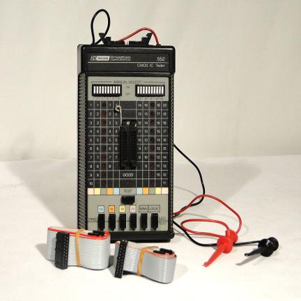
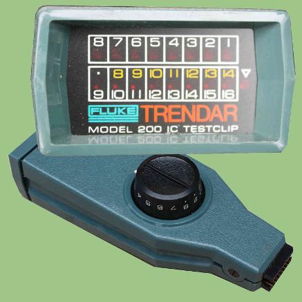
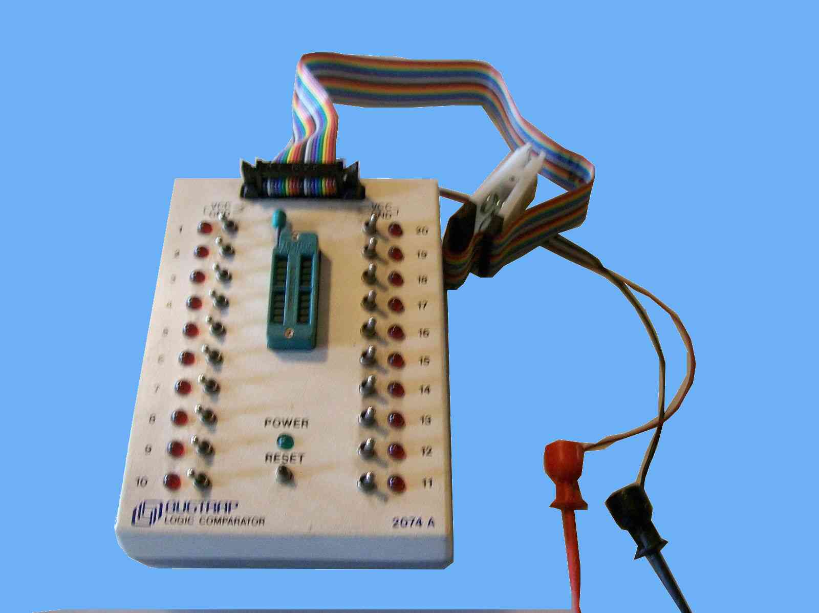
*****************************************************************************************************************
*****************************************************************************************************************
Wanted: (Your Notebook Notes)
Settings for your Comparator (Keep a Notebook record of the chips you figure out the settings for.)
FORTUNATELY - several good brands of comparators were made - this assists technicians and repair shops etc check ICs in-circuit. UNFORTUNATELY - I know of no book or website or other instructions etc which list the dipswitch settings for the testers for 7400 series, 4000 series 4500 series ICs.
Fluke Trendar 200 (rotary dial setting)
BK Precision 552 CMOS IC Tester (dip switch settings)
BK Precision 551 Digital IC Tester (dip switch settings)
Bugtrap (toggle switch settings)
HP comparator (using universal board dip switch settings or DIY blank cards you have soldered a chip onto)
Other brand or model comparator not listed here?
I am not affilliated with any of the above namebrands which are all great testers.
Attention Technicians:
When you work on your arcade boards, computer repairs, board level repairs etc Keep a notebook record of your dipswitch settings, rotary knob settings, toggle switch settings for each and every chip that you have PERSONALLY tested and figured out on your own. I need those settings in order to make a compilation. If you add up the number of digital TTL common chips and CMOS common chips - which we ALL want to test and use our comparators to the FULLEST capabilities. It is VERY UNFORTUNATE that no chiplist and settings list exist to this day. WHY_OH_WHY would manaufacturers produce a GREAT product but provide no settings? Makes no sense to me. Please help by emailing me a chiplist for ANY of the above comparators ALONG with the settings for those chips you have personally used. In the case of HP comparator - dipswitch setting notes are helpful. In the case of HP comparator using Do-It-Yourself swappable cards - send a photo of front and backside of DIY card.
A note to the person(s) who will invariably email or phone saying, "just look it up in the specifications of the IC datasheet" YOU MISSED THE POINT Buddy!!!! There are hundred of ICs. It would take any one person YEARS to do that One-by-one. A chiplist with dipswitch settings is necessary. Otherwise these wonderful tools just sit in your closet - unused. Save your notebook notes on each and every chip you figure this out for. So everyone doesnt need to REINVENT the wheel - as a figure of speech. Why doesnt this already EXIST - this compilation of dipswitch settings? I know of no-one else who has done this.
Your help in this matter is appreciated. One chip dipswitch settings, 10 chips settings, 100 chip settings Whatever you have- its appreciated and will add to this section.
EMAIL and Phone number
drviragopete@att.net
(847) 454-7858 between 11am and 7pm daily
Dr Virago Pete
*****************************************************************************************************************
*****************************************************************************************************************
My Basic Component Testing Notes
How to basic test Varistor 2-pin (round disc looks like a 25cent coin)
Basic test using a Multimeter set to diode test. There should be no reading "OL" for a good varistor. In otherwords - a good varistor it apears to be open just like a blown fuse. No continuity between legs Jan2016
How to basic test Thermister 2 pin (round disc looks like a 25cent coin)
Using multimeter set to Continuity. Should give a reading and beep for a good one. If no beep and no reading then bad. Common reading for thermister on TV board is 0004.3 to 0006.5 but varies with model.
Square black Sometimes marked "PTC" looks like a relay in TV boards - but only has 3 legs. Test legs 2 and 3 using multimeter continuity test. Common values are 0004.3 to 0006.5 but can vary with model of PTC. If no beep and reading then bad.
A bad thermister can cause a TV to refuse to power on. Jan2016
Miscellaneous Notes
DLP lamp replacement (brand new) for Toshiba TV has no continuity when tested on a multimeter - it is an arc lamp. A bad lamp looks exploded and element inside the glass outer shell module is blatantly obvious shattered. The outside shell prevents the shattered pieces from spraying everywhere- it contains the shrapnel. I saw no glass debris inside the set. Jan2016
Bridge Rectifier 3-phase used in grid tie inverters SQL50A and SQL100A have 5 pins. Some solar vendors are selling unmarked clones with + and - reversed beware. Good part should have + and 3 pins looks like diodes. Also - and 3 pins looks like diodes. Blown will look like a continuity at any given internal diode - or show open. 100A is much bigger in size than 50A and would not fit in case. 1 vendor was selling SQL50A at 1200V and others selling at 1000V. I chose 1200V 2-pack from China and was a good part. Much heat needed to replace it due to heatsinking 100watts soldering iron. I added Plastidip coating of soldered joints. Symptom load dump always on - short between load port screw terminal and other 3-phase screw terminal caused by shorted SQL50A (1 bad diode inside). Jan2016
________________________________________________________________________________________________________
I own 13ea Professional Integrated Circuit IC Testing Machines - Each Tester Tests a multitude of Integrated Circuit chips.
These machines are useful for testing and perform very well. Some chips are unique to each machine - so I have provided columns of data for reference / data.
I have also included my own notes so I can refer to this list when testing the chip - for example some chips require the use of an adapter board and my own list helps me when testing.
Some of my testers have "Loop" fuction where they continuously test the chip - cycling and looking for intermittant problems and glitches in IC chips - which helps pinpoint bad IC chips which have intermittant issues. Some tests can take 1 second and other tests 80seconds and other tests can be run continuously for as long as the chip is plugged into the socket.
Some of these testers can identify unmarked IC chips as it compares the chip to its built-in list of chips / databank / database using the "Search" function.
Why have so many testers?
It isnt sufficient to have just one tester. When I check an IC chip to see whether it is a good chip - I test it on multiple testers - as many as I have that will test that IC. See some testers may PASS that IC chip and one or more testers may FAIL it. Well which is the correct diagnosis? I build a list of FALSE PASS or FALSE FAILS and have a pretty good idea on which ones (tester to ic compatibility list) to disregard for certain ICs as there isnt 100% accuracy in any tester. If ALL of my testers PASS the IC the certainty in that IC is very high. If any of the testers FAIL a chip it may be a weakened or bad chip or borderline pass/fail chip (or a defect in the tester itself where the data was entered crrectly in its ROM or EPROM truth tables) Also each tester has its own threshold for what it considers pass/fail which may differ from other testers' threshold. ALL are good testers and all contribute greatly to the confidence level in knowing whether the IC under test is a good one and worthy of being used in a circuit.
A blown IC chip will FAIL on all of my testers. Not all bad chips are Blown. Some bad chips are just weak and may actually PASS on some testers. A bad chip will FAIL on one or more testers. Every tester I own pulls-its-own-weight and has caught some bad chips that the other testers didnt catch. That is why I value having as many "second opinions" as possible. Even brand new IC chips - sometimes are defective and should be tested before use. Weakened chips often cause a circuit to cease functioning- a weak chip upsets the math that was used when designing that circuit. Only looking for Blown chips - is not the answer to all repairs. It is important to replace Blown parts and weak parts. It takes skill to know when a part is good-enough. If it fails any of my testers- that IC is not-good-enough - even if the other testers PASS it (With the exception of a known truth table defect with that particular chip/tester.) Each tester has its own testing strategy and parameters it looks for.
You should not look at it as - which tester is the best? ALL testers are good and when used as a team as one tool - can catch IC chips which are bad or weak. All testers use a different testing method and parameters. If I relied on only one tester - some bad / weak chips would go undetected.
The more testers I use - the higher the level of confidence in the diagnosis.
An Analogy of A Drivers License Test - relating this to IC Tester
I'm elaborating on why each IC tester is valuable. And you should not think of IC testers as being better or worse - than each other. I value each and every tester that I own. All of them contribute to the confidence level of that Chip being good.
Lets say that each IC tester is like each test you are given when you go to to renew/obtain your drivers license. You may be given some tests 1. Written Test, 2. Behind the wheel tests A Parallel Park B Seatbelt C Speed Limit D Use of Blinkers D Braking E Merging into traffic, etc too many to list. If you expect to get your drivers license but you failed to use your blinkers - you flunked no matter how well you did on any other tests.
Each IC tester uses a different testing strategy - each maker of the IC tester has his/her own idea of how to go about testing the IC to make sure it works. Lets call IC tester #1 a parallel parking test. Lets say the IC test OK or PASS for parallel parking - is this IC good - probably yes. But I will still test that IC on all of my IC testers on-by-one and every once in a great while - I will find that the chip - that has passed every one of my testers - but one. And that chip FAILS on one tester. So somehow the test that the IC tester gave it - did not hold up to scrutiny. I VALUE THAT - GOOD CATCH and it may be the difference between finding that intermittant or hard-to-find problem. I hope the Drivers License analogy makes this clearer. It is not that the chip FOOLed the other testers - that chip passed the Drivers License Written Test, It used its blinkers correctly, it merged and changed lanes correctly. But it failed when it came time to parallel park - so to speak. It was a good catch and replacing that IC chip will be beneficial.
Sometime a chip will FAIL on one tester and PASS on all the rest. It is not always on one tester model. Sometimes another model will catch an error. It is always on a different tester. All of these tester pull-their-own weight and contribute greatly to catching those hard-to-find problems or glitches in circuits. I am always on the lookout for a new IC tester to add to my daily-use equipment. How often does this happen - maybe one out of every 200 -2000 chips (as found in used equipment being troubleshooted) and I have tested thousands. I save these bad chips - they are valuable because they can be used to scrutinize an IC tester purchase. So the bad chip that cannot "parallel park" but is able to pass the "written test" and successfully "merges lanes" now becomes a tool to scrutinze a newly purchased IC tester added to my collection. I have about a dozen bad chips like this - all of them trigger a FAIL response from a totally dfferent tester. I mark these "bad" chips so they do not get reused in a circuit.
If a person emails me or phones me and asks, "so which IC tester is the best one." I'm telling you right now - you missed the point. The point is that all IC testers are good. They must all work together as a team. All ICs must be tested on multiple testers - as many as possible. A good chip will pass all IC testers- uless there is data entry error in that tester for that particular chip- which some of them have this. And I make note of this - so I know when at the results of the PASS or FAIL is due to a data entry error in the ROM of that Tester. I'm calling this "experience" in understanding what is being displayed.
I know of no-one else in the world who does this.
Intermittant chips
When I find a chip that FAILs on that tester - it generally continues to FAIL on that TESTER - when doublechecked or triplechecked. Even more rare is a chip which will give an intermittant error on one tester - and then you ask yourself - hmm thats strange - did I just see that? An example is my ISI SEM Microscope repair notes (click on the link at top of page to see more about this) regarding a Digital Capture Card. If in doubt - replace the chip and make note of it.
Dr Virago Pete
Phone (847) 454-7858 after 7pm daily
email drviragopete@att.net
Illinois, USA
My assistance is not free - reasonable fee - call or email to inquire.
My Notes about TTL Digital Logic Chips etc
7400 Series Chips usually have the following ratings and specifications printed on the chip (For example 74LS51 or 74HC85 ...)
STD, L, LS, S, H, C, HC, HCT
Temperature range up to approx 160degrees F
5400 Series Chips usually have the following ratings and specifications printed on the chip (For example 54H01, 54C86 ...)
STD, L, LS, S, H, C, HC, HCT
Temperature range up to approx 300degrees F
(5400 series chips are considered the"military specification version" of the 7400 series family of chips. The main difference is temperature rating is vastly higher and rated to survive in a hotter environment. Not all 5400 series chips are rated at 300degrees F - check the datasheet on that particular chip/mfg as some differ.)
Note 5400 series chips and 7400 series chips are generally interchangeable except for temp range is different. (Some exceptions to this may exist)
Most of my Testers are for Digital IC Chips. I can test a few Analog Linear Chips Also- refer to lists (below).
Some chip mfgs have their own numbering system but the chip itself is compatible with a standard chip model - cross reference to standard ICs.
A few of my testers require adapters for certain chips - but most of these same chips do not require an adapter on another one of my testers. By simply using a different tester for that chip - very few adapters are actually needed - because for that chip - there exists another tester which requires no adapter - in all but a few cases.
While all of my testers test mostly the same chips - there are substantial differences in the lists - some testers skip certain chips. All of my testers have a unique set of chips they test and each one handles the testing process differently. When verifying a chip - I try to test it on as menay testers as possible - noting the result for each tester.
For example chip 75L60 can only be tested on the "Chiptester CT-2" as the test is unique to that tester. 74255 can only be tested on the YBD as the test is unique to the tester. 74H61 can only be tested on the GUT as the test is unique to that tester ...
For example 7400 can be tested on all of my testers
What Do the Letter Codes Mean?
74 = Standard TTL
74H = High speed TTL
74L = Low Power TTL
74S = Schottky TTL
74LS = Low Power Schottky TTL
74AS = Advanced Schottky TTL
74ALS = Advanced Low Power Schottky TTL
74C = Metal Gate (Pins are compatible with TTL)
74HC = Silicon Gate High Speed (Pins are compatible with TTL)
74HCT = Silicon Gate High Speed (compatible with TTL)
***Some of the above may not be interchangeable and
check tester before plugging in as some may not be
able to be tested on all testers
I have included a Bug and Glitch list of IC chips which confuse the testers or give False results. False Pass or False Fails and notes regarding special circumstances- see the bottom of this page - at the very end of this page on the right-hand side. Viewer/reader contributions to this growing list is welcome. It is not my intention to knock any tester. I value the "second opinion" of additional IC testers as it adds to the level of confidence that the test results are indeed correct. Knowing which testers give questionable or incorrect results is important. None of my testers are perfect - all of them working together - allows the confidence level to be very high - in obtaining test results and identifying bad parts. It is not intended to say one IC Tester is better or worse. All of them are very good. I'm glad to have them all.
The following lists are hand entered/typed so there may be typos. Sometimes the manuals I was reading apeared to have typo errors so there may be some inaccuracies although this should be minimal.
TESTER #1 "GUT"
List of IC Chips I can Test
(I use various models of IC Chip Testers as no one tester
can test every chip)
7400 Series
7400
7401
7402
7403
7404
7405
7406
7407
7408
7409
7410
7411
7412
7413
7414
7415
7416
7417
7418
7419
7420
7421
7422
7423
7424
7425
7426
7427
7428
7430
7432
7433
7434
7435
7436
7437
7438
7439
7440
7441
7442
7443
7445
7446
7447
7448
7449
7450
7451
74H52
7453
7454
74H54
7455
7460
74H61
7463
7464
7465
7470
7472
7473
7474
7475
7477
7478
74H78
7480
7481
7482
7483
7484
7485
7486
7487
7488
7489
7490
7491
7492
7493
7494
7495
7496
74105
74107
74109
74110
74111
74112
74113
74114
74116
74125
74126
74128
74132
74133
74134
74135
74136
74137
74138
74139
74140
74141
74142
74143
74144
74145
74147
74148
74150
74151
74152
74153
74154
74155
74156
74157
74158
74159
74160
74161
74162
74163
74164
74165
74166
74168
74169
74170
74173
74174
74175
74176
74177
74178
74179
74180
74181
74182
74183
74184
74185
74189
74190
74191
74192
74193
74194
74195
74196
74197
74198
74199
74230
74231
74240
74241
74242
74243
74244
74245
74246
74247
74248
74249
74251
74253
74245
74246
74247
74248
74249
74251
74253
74257
74258
74259
74260
74265
74266
74273
74274
74276
74279
74280
74283
74289
74290
74293
74295
74298
74299
74322
74323
74347
74348
74350
74351
74352
74353
74356
74363
74364
74365
74366
74367
74368
74373
74374
74375
74377
74378
74379
74382
74386
74390
74393
74395
74399
74412
74425
74426
74445
74447
74465
74446
74447
74448
74490
74518
74519
74520
74521
74522
74533
74534
74539
74540
74541
74563
74564
74573
74574 (Note: Must Be selected manually through Menu)
74575
74576
74580
74597
74604
74605
74620
74621
74622
74623
74368
74639
74640
74641
74642
74644
74645
74646
74647
74652
74654
74668
74669
74670
74682
74683
74684
74685
74688
74689
74756 (Note: Must be Selected Manually Through Menu)
74795
74796
74797
74798
74804
74805
74808
74810
74811
74821
74827
74832
74841
74874
741000
741002
741003
741004
741005
741008
741010
741011
741020
741034
741035
741036
741244
741245
-----------------------------------------------------------------------------------
List of IC Chips I can Test
(I use various models of IC Chip Testers as no one tester
can test every chip)
CMOS 4000 Series Chips
----------------------
4000
4001
4002
4006
4007
4008
4009
4010
4011
4012
4013
4014
4016
4017
4018
4019
4020
4021
4022
4023
4024
4025
4026
4027
4028
4029
4030
4032
4033
4035
4038
4040
4041
4042
4043
4044
4048
4049
4050
4051
4052
4053
4054
4055
4056
4060
4063
4066
4067
4068
4069
4070
4071
4072
4073
4075
4076
4077
4078
40H78
4081
4082
4085
4086
4093
4094
4095
4096
4097
4099
40100
40101
40102
40103
40104
40106
40109
40110
40147
40160
40161
40162
40163
40174
40175
40181
40182
40192
40193
40194
40257
MC140 Series Chips
(Enter all these dropping off
the MC1 for example enter MC14000 as 4000)
------------------
MC14000
MC14001
MC14002
MC14006
MC14007
MC14008
MC14009
MC14010
MC14011
MC14012
MC14013
MC14014
MC14016
MC14017
MC14018
MC14019
MC14020
MC14021
MC14022
MC14023
MC14024
MC14025
MC14026
MC14027
MC14028
MC14029
MC14030
MC14032
MC14033
MC14035
MC14038
MC14040
MC14041
MC14042
MC14043
MC14044
MC14048
MC14049
MC14050
MC14051
MC14052
MC14053
MC14054
MC14055
MC14056
MC14060
MC14063
MC14066
MC14067
MC14068
MC14069
MC14070
MC14071
MC14072
MC14073
MC14075
MC14076
MC14077
MC14078
MC140H78
MC14081
MC14082
MC14085
MC14086
MC14093
MC14094
MC14095
MC14096
MC14097
MC14099
MC140100
MC140101
MC140102
MC140103
MC140104
MC140106
MC140109
MC140110
MC140147
MC140160
MC140161
MC140162
MC140163
MC140174
MC140175
MC140181
MC140182
MC140192
MC140193
MC140194
MC140257
---------------------------------------------------------------------------------------
List of IC Chips I can Test
(I use various models of IC Chip Testers as no one tester
can test every chip)
CMOS 4500 Series Chips
----------------------
4501
4502
4503
4504
4506
4508
4510
4511
4512
4513
4514
4515
4516
4518
4519
4520
4522
4526
4527
4529
4539
4543
4544
4547
4551
4553
4555
4556
4560
4561
4566
4572
4581
4584
4585
CMOS MC145 Series Chips
(Enter all these dropping off
the MC1 for example enter MC14500 as 4500)
-----------------------
MC14501
MC14502
MC14503
MC14504
MC14506
MC14508
MC14510
MC14511
MC14512
MC14513
MC14514
MC14515
MC14516
MC14518
MC14519
MC14520
MC14522
MC14526
MC14527
MC14529
MC14539
MC14543
MC14544
MC14547
MC14551
MC14553
MC14555
MC14556
MC14560
MC14561
MC14566
MC14572
MC14581
MC14584
MC14585
-------------------------------------------------------------------------------
List of IC Chips I can Test
(I use various models of IC Chip Testers as no one tester
can test every chip)
DRAM Dynamic RAM Series Chips
--------------------------
4164
41256
411000
414000
4464
44256
441000
4464
44256
441000
4464
44256
User Manual for GUT IC Tester is here
This tester's version is 2.16 and is slighly different than this manual.
For example my tester does not test ULN2003 and various ULN chip as I cant find it in the menu. The pdf file is for model XXXXA where my tester does not have the A in its model number. My hunch is the A stands for a few analog chips which were added.
One of my other IC testers (TSH) can test the ULN chips- dont worry - I can test ULN chips on another tester.
This tester is very fast - performs searches and tests quickly.
|
|
GUT+USER+MANUAL.pdf Size : 122.859 Kb Type : pdf |
TESTER #3 "VZ"
List of IC Chips I can Test
(I use various models of IC Chip Testers as no one tester can test every chip)
7400 Series
7400
7401
7402
7403
7404
7405
7406
7407
7408
7409
7410
7411
7412
7413
7414
7415
7416
7417
7418
7419
7420
7421
7422
7423
7424
7425
7426
7427
7428
7430
7432
7433
7434
7435
7437
7438
7439
7440
7441
7442
7443
7445
7446
7447
7448
7449
7450
7451
7453
7454
7455
7460
7463
7464
7465
7470
7472
7473
7474
7475
7476
7477
7478
7480
7481
7482
7483
7484
7485
7486
7485
7486
7492
7493
7495
74100
74104
74105
74107
74109
74112
74113
74114
74125
74126
74132
74133
74134
74135
74136
74137
74138
74139
74140
74141
74145
74147
74148
74150
74151
74152
74153
74154
74155
74156
74157
74158
74160
74161
74162
74163
74164
74165
74166
74168
74170
74173
74174
74175
74180
74181
74182
74183
74190
74191
74192
74193
74194
74195
74240
74241
74242
74243
74244
74245
74246
74247
74248
74249
74251
74253
74245
74246
74247
74248
74249
74251
74253
74257
74258
74259
74260
74265
74266
74273
74279
74280
74283
74290
74293
74295
74298
74299
74323
74347
74348
74351
74352
74353
74363
74364
74365
74366
74367
74368
74373
74374
74375
74377
74378
74386
74390
74393
74399
74425
74426
74465
74466
74467
74468
74518
74519
74520
74520
74521
74522
74533
74534
74540
74541
74563
74564
74573
74574
74575
74576
74580
74597
74620
74621
74622
74623
74638
74639
74640
74641
74642
74643
74644
74645
74646
74670
74688
74689
-------------------------------------------------------------------------------------
List of IC Chips I can Test
(I use various models of IC Chip Testers as no one tester can test every chip)
5400 Series
5400
5401
5402
5403
5404
5405
5406
5407
5408
5409
5410
5411
5412
5413
5414
5415
5416
5417
5418
5419
5420
5421
5422
5423
5424
5425
5426
5427
5428
5430
5432
5433
5434
5435
5437
5438
5439
5440
5441
5442
5443
5445
5446
5447
5448
5449
5450
5451
5453
5454
5455
5460
5463
5464
5465
5470
5472
5473
5474
5475
5476
5477
5478
5480
5481
5482
5483
5484
5485
5486
5485
5486
5492
5493
5495
54100
54104
54105
54107
54109
54112
54113
54114
54125
54126
54132
54133
54134
54135
54136
54137
54138
54139
54140
54141
54145
54147
54148
54150
54151
54152
54153
54154
54155
54156
54157
54158
54160
54161
54162
54163
54164
54165
54166
54168
54170
54173
54174
54175
54180
54181
54182
54183
54190
54191
54192
54193
54194
54195
54240
54241
54242
54243
54244
54245
54246
54247
54248
54249
54251
54253
54245
54246
54247
54248
54249
54251
54253
54257
54258
54259
54260
54265
54266
54273
54279
54280
54283
54290
54293
54295
54298
54299
54323
54347
54348
54351
54352
54353
54363
54364
54365
54366
54367
54368
54373
54374
54375
54377
54378
54386
54390
54393
54399
54425
54426
54465
54466
54467
54468
54518
54519
54520
54520
54521
54522
54533
54534
54540
54541
54563
54564
54573
54574
54575
54576
54580
54597
54620
54621
54622
54623
54638
54639
54640
54641
54642
54643
54644
54645
54646
54670
54688
54689
-----------------------------------------------------------------------------------
List of IC Chips I can Test
(I use various models of IC Chip Testers as no one tester can test every chip)
CMOS 4000 Series Chips
----------------------
4000
4001
4002
4006
4007
4008
4009
4010
4011
4012
4013
4014
4016
4017
4018
4019
4021
4022
4023
4024
4025
4026
4027
4028
4029
4030
4032
4033
4035
4038
4040
4041
4042
4043
4044
4048
4049
4050
4051
4052
4053
4055
4056
4060
4063
4066
4067
4068
4069
4070
4071
4072
4073
4075
4076
4077
4081
4082
4085
4086
4093
4094
4095
4096
4097
4099
40101
40102
40106
40109
40147
40160
40162
40163
40174
40175
40192
40193
40194
40257
MC140 Series Chips
------------------
MC14000
MC14001
MC14002
MC14006
MC14008
MC14009
MC14010
MC14011
MC14012
MC14013
MC14014
MC14016
MC14017
MC14018
MC14019
MC14021
MC14022
MC14023
MC14024
MC14025
MC14026
MC14027
MC14028
MC14029
MC14030
MC14032
MC14033
MC14035
MC14038
MC14040
MC14041
MC14042
MC14043
MC14044
MC14048
MC14049
MC14050
Mc14051
Mc14052
MC14053
MC14055
MC14056
MC14060
MC14063
MC14066
MC14067
MC14068
MC14069
MC14070
MC14071
MC14072
MC14073
MC14075
MC14076
MC14077
MC14081
MC14082
MC14085
MC14086
MC14093
MC14094
MC14095
MC14096
MC14097
MC14099
MC140101
MC140102
MC140106
MC140109
MC140147
MC140160
MC140162
MC140163
MC140174
MC140175
MC140192
MC140193
MC140194
MC140257
---------------------------------------------------------------------------------------
List of IC Chips I can Test
(I use various models of IC Chip Testers as no one tester can test every chip)
CMOS 4500 Series Chips
----------------------
4501
4502
4503
4504
4506
4508
4510
4511
4513
4514
4515
4518
4519
4520
4529
4530
4531
4532
4543
4553
4555
4556
4572
4584
4585
CMOS MC145 Series Chips
-----------------------
MC14501
MC14502
MC14503
MC14504
MC14506
MC14508
MC14510
MC14511
MC14513
MC14514
MC14515
MC14518
MC14519
MC14520
MC14529
MC14530
MC14531
MC14532
MC14543
MC14553
MC14555
MC14556
MC14572
MC14584
MC14585
Notes
My tester is Vizatek model VZ-4 and looks to be similar or nearly identical to Kitek DICT-01. I opened up my tester and found the circuit board which states "DICT01" on the circuit board.
Never connect AC/DC adapter to this IC tester. Use 9V square battery only. A look inside the unit reveals that the power jack is unregulated. Even though there apears to be a voltage regulator present - trust me it is not regulated from the jack. Use of battery will not light the backlight. Use of power jack will light the backlight.
Never use the power jack. I suggest putting a sticker over the power jack so someone doesnt accidently plug it into a ac/dc power adapter.
TESTER #5 "MCT"
List of IC Chips I can Test
(I use various models of IC Chip Testers as no one tester
can test every chip)
7400 Series
7400
7401
7402
7403
7404
7405
7406
7407
7408
7409
7410
7411
7412
7413
7414
7415
7416
7417
7418
7419
7420
7421
7422
7424
7425
7426
7427
7428
7430
7431
7432
7433
7434
7435
7437
7438
7439
7440
7442
7443
7445
7446
7447
7448
7449
7450
7451
7452
7453
7454
7455
7460
7461
7462
7463
7464
7465
7470
7471
7472
7473
7474
7475
7477
7478
7481
7482
7483
7484
7485
7486
7489
7490
7491
7492
7493
7494
7495
7496
74107
74108
74109
74110
74111
74112
74113
74114
74125
74126
74128
74131
74132
74133
74134
74135
74136
74137
74138
74139
74140
74141
74142
74145
74147
74148
74151
74152
74153
74155
74156
74157
74158
74160
74161
74162
74163
74164
74165
74166
74168
74170
74173
74174
74175
74180
74183
74189
74190
74191
74192
74193
74194
74195
74230
74231
74240
74241
74242
74243
74244
74245
74246
74247
74248
74249
74251
74253
74246
74247
74248
74249
74251
74253
74256
74257
74258
74259
74260
74265
74266
74273
74276
74278
74279
74280
74283
74290
74293
74295
74298
74299
74322
74323
74348
74350
74351
74352
74353
74363
74364
74365
74366
74367
74368
74373
74374
74375
74376
74377
74378
74379
74386
74390
74393
74399
74425
74426
74440
74441
74442
74443
74444
74445
74447
74448
74465
74446
74447
74448
74490
74518
74519
74520
74521
74522
74533
74534
74540
74541
74563
74564
74573
74574
74576
74580
74590
74620
74621
74622
74623
74638
74639
74640
74641
74642
74643
74644
74645
74668
74669
74670
74688
74689
74795
74796
74797
74804
74805
-----------------------------------------------------------------------------------
List of IC Chips I can Test
(I use various models of IC Chip Testers as no one tester
can test every chip)
CMOS 4000 Series Chips
----------------------
4000
4001
4002
4006
4007
4008
4009
4010
4011
4012
4013
4014
4016
4017
4018
4019
4020
4021
4022
4023
4025
4026
4027
4028
4029
4030
4032
4033
4035
4038
4040
4041
4042
4043
4044
4048
4049
4050
4051
4052
4053
4054
4055
4056
4060
4063
4066
4068
4069
4070
4071
4072
4073
4075
4076
4077
4078
4081
4082
4085
4086
4093
4094
4095
4096
4099
40101
40102
40103
40105
40106
40109
40160
40161
40162
40163
40174
40175
40192
40193
40194
---------------------------------------------------------------------------------------
List of IC Chips I can Test
(I use various models of IC Chip Testers as no one tester
can test every chip)
CMOS 4500 Series Chips
----------------------
4501
4502
4503
4504
4506
4510
4511
4512
4516
4517
4518
4519
4520
4524
4529
4532
4538
4543
4553
4555
4556
4572
4582
4584
4585
-------------------------------------------------------------------------------
List of IC Chips I can Test
(I use various models of IC Chip Testers as no one tester
can test every chip)
****Note *****
DRAM Memory chips go upside down in socket
DRAM Dynamic RAM Series Chips
--------------------------
4164
41256
411000
4416
41416
4464
41464
44256
414256
Notes
My IC Tester is "Modular Circuit Technology model MOD-HIC IC Tester" and is similar to "Ming HT-21 Handy Tester" or "Hi Lo Systems Prufer-20 Handy Tester" which looks to be a nearly identical or very similar tester.
This tester is very fast - performs searches and tests quickly.
|
|
Instructions MOD-HIC IC Tester.JPG Size : 145.341 Kb Type : JPG |
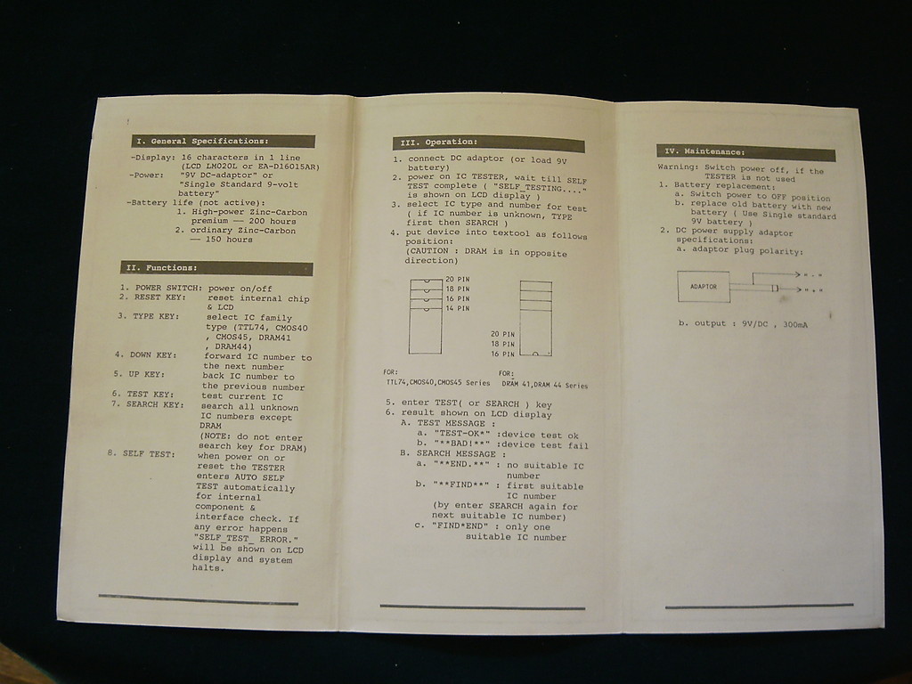
TESTER #6 "TSH"
List of IC Chips I can Test
This tester does not have a list of each and every chip that it can test in the instructions. Instead it lists general categories of chips such as 7400 series and more which are listed below. Using the IC Tester's menu - I have listed each and every unique chip that it specifically shows in the device's LCD menu.
7400 Series
----------------------
CMOS 4000 Series Chips
----------------------
MC140 Series Chips
(Enter all these dropping off
the MC1 for example enter MC14000 as 4000)
----------------------
CMOS 4500 Series Chips
----------------------
CMOS MC145 Series Chips
(Enter all these dropping off
the MC1 for example enter MC14500 as 4500)
-----------------------
HEF400 series
-----------------------
Misc listed in LCD Menu
LM324
LM358
LM339
LM393
LM2902
LM2904
LM741
TL082
TL084 (Can also be used to basic test TL074- just select
TL084 in the menu but insert a TL074 chip)
NE555
75175
75176
75C1168
MAX232
MAX485
82C251
MC3487
26S10
26LS31
26LS32
ULN2003
ULN2803
Notes:
This tester is very good at distinguishing between HC and LS 7400 series chips. It will fail a LS chip if tested under the HC mode. It will fail a HC chip if tested under the LS mode. LS is low speed and HC is high speed and this tester can test high speed and low speed speed paramenters very well.
This tester also tests zener diodes and gives the measured voltage value which is a very rare feature. This is much better than other common semiconductor testers (most of these cheap semiconductor testers are sold online as a bare pcb - I have one too) for zener testing because the competition products give the breakdown voltage which is of no value. This IC tester's zener test gives the actual voltage value which can be compared to specification sheets of the diode to determine if the zener diode is within tolerance. Zener diode test is performed in the righthand side of the IC socket in the lowest 2 holes. Zener function "ZD" is selected from the menu.
This tester can also test optocouplers/opto isolators having 4 pins. The 4-pin IC is placed in the socket at the lowest position - in otherwords - furthest away from the zif socket's lever. Selectr "LIGHT" from the LCD menu for optocoupler testing. Optocoupler compatibility list is unknown.
I am starting to build a DIY chiplist for this tester TSH-02F as no chiplist was included in the brief instruction sheet. I am building this list from scratch by going through the menu chip-by-chip and seeing if that number produces a "not supported" - or "fault" if it says fault with no IC in the socket that means it is a testable chip. if it says "not supported" that means it is not a testable chip - according to its built-in chiplist.
7400 LS and HC (Both Lists in this machine are the same)
--------------
7400
7401
7402
7403
7404
7405
7406
7407
7408
7409
7410
7411
7412
7413
7414
7415
7416
7417
7418
7420
7421
7422
7425
7426
7427
7428
7430
7432
7437
7438
7440
7442
7447
7450
7451
7452
7455
7458
7460
7461
7462
7465
7473
7474
7485
7486
74101
74109
74112
74113
74124
74125
74126
74132
74133
74136
74137
74138
74139
74140
74145
74147
74148
74149
74151
74153
74157
74158
74160
74161
74162
74163
74164
74165
74166
74173
74174
74175
74190
74191
74192
74192
74193
74194
74195
74237
74240
74241
74242
74243
74244
74245
74251
74253
74257
74258
74259
74260
74266
74273
74280
74283
74292
74293
74294
74298
74299
74354
74356
74365
74366
74367
74368
74373
74374
74375
74377
74386
74390
74393
74533
74534
74540
74541
74563
74564
74573
74574
74589
74595
74597
74640
74643
74688
(done)
CD4000 series CMOS
-----------
4000
4001
4009
4010
4011
4012
4013
4015
4016
4017
4018
4019
4021
4022
4023
4024
4025
4027
4028
4029
4030
4031
4040
4041
4042
4043
4044
4048
4049
4050
4051
4052
4053
4054
4056
4066
4068
4070
4071
4072
4073
4075
4076
4077
4078
4081
4082
4093
40106
40161
40162
40174
40175
40192
40193
40194
4500 series (4500 is not supported on this tester)
------------
4501
4503
4504
4506
4510
4511
4512
4516
4518
4519
4520
4529
4532
4538
4543
4555
4572
4584
14500 Series (14500 is not supported on this tester)
------------------
14501
14503
14504
14506
14510
14511
14512
14516
14518
14519
14520
14529
14532
14538
14543
14555
14572
14584
HEF4000 series LOCMOS
------------
HEF4000
HEF4001
HEF4009
HEF4010
HEF4011
HEF4012
HEF4013
HEF4015
HEF4016
HEF4017
HEF4018
HEF4019
HEF4021
HEF4022
HEF4023
HEF4024
HEF4025
HEF4027
HEF4028
HEF4029
HEF4030
HEF4031
HEF4040
HEF4041
HEF4042
HEF4043
HEF4044
HEF4048
HEF4049
HEF4050
HEF4051
HEF4052
HEF4053
HEF4054
HEF4056
HEF4066
HEF4068
HEF4070
HEF4071
HEF4072
HEF4073
HEF4075
HEF4076
HEF4077
HEF4078
HEF4081
HEF4082
HEF4093
HEF40106
HEF40161
HEF40162
HEF40174
HEF40175
HEF40192
HEF40193
HEF40194
(my note: 7400 series done 12/30/13)
(my note: 4500 & 14500 series done 12/16/14)
(my note: 4000 & HEF400 series done 12/16/14)
(this growing DIY chiplist to be continued as I have time)
As of 12/16/14 I believe this chiplist is now complete.
This tester does not come with a list of chips that are testable - instead the tester documentation gives broad families of chips which it can test - without listing individual chips in that documentation.
I have found through hands-on experience that certain chips test fine and others display "not supported"
"Not Supported" Chips which I personally tested
SN74LS169BN
SNF169PC
SN74154N (to big to fit in socket)
SN74LS03N - "fault" LS and HS model may be reversed
NTE74LS03 - "fault" LS and HS model may be reversed
S 74F377N - "fault" Not sure if works?????
SN74LS279AN
SN74LS189AN
SNF189PC
SN74LS629N
SN74LS75N
SN74ALS756AN
S 74F350N
SN74ALS874BNT (long Ic)
SN74LS629N
74HC107N
SN7472J
Undocumented YES Supported Chips List
(IC Chips I have personally tested to work on TSH tester)
SN74LS00N
S 74F00N
SN74LS02N
S 74F02N
SN74LS04N
SN7406N
SN7407N
S 74F08N
SN74LS10N
SN74LS20N
SN74LS27N
SN74LS30N
SN74LS74AN
S 74F74N
SN74LS86AN
SN74LS125AN
SN74LS132N
SN74LS133N
S 74F138N
SN74LS153N
SN74LS157N
SN74LS158N
SN74LS163AN
S 74F163AN
SN74LS174N
SN74LS175N
S 74F175N
SN74LS240N
74F240PC
SN74LS243N
SN74LS244N
S 74F244N
S 74LS273N A
SN74LS374N
S 74F374N
SN74LS377N
S 74F377N
SN74ALS574AN
SN74AS574N
SN74LS574AN
SN74LS576AN
Linear IC/Parts Testing Notes
LM339 - place chip at top of socket pin 1 furthest up
PC817 Opto 4-pin chip lowest pins on socket (menu=Light install backwards "0.17V" upside up "Open" partial test
Transistor test (Menu = TR) only identifies it as PNP or NPN and gives pin orientation but does not give value or show leakage - only pinout and PNP/NPN. Use last three holes on socket to the left side.
Zener Diode test - use lowest/last two holes on righthand side of socket. Menu = ZD. Test rightside up and backwards manually flipping the zener diode.
This tester is a very popular item at a very inexpensive price. It seems that the hardware is able to handle both TTL digital chips and analog chips as there are a few analog chips in its internal library. I hope that the popularity of this tester inspires the mfg to come out with a Linear IC tester version or users figure out a MOD to add chips to the internal list. The current price for this tester in 8/13 is approx $60 although I paid double that for mine since it was purchased before USA online release and I purchase mine from SIngapore and had it imported.
The lack of a chip list in the documentation - and the usefulness of this tester - inspired me to create this list. Reader/user data to be added to this list is welcome and appreciated. I have tested many hundreds of chips - most chip models - with many duplicates of same chips models - the above lists reflects all chips I have tested on this tester - as I kept detailed notes.
Note Big-auction-site was swamped with the TSH-02F "yellow sticker IC tester" just like mine that I purchased from SIngapore. The price on big auction site was between $55-75US depending on the seller sometimes with free shipping and sometimes not. After a few months another similar tester model TSH-06F the "blue sticker IC tester" at approx the very same price was competing. It is my hunch that these 2 testers are functionally identical or extremely similar - except there are 2 extra buttons on the blue tester. It is my hunch that these 2 extra buttons are for scrolling through the internal chiplist. My yellow tester requires each and every chip number to be entered manually.
So the scroll buttons would have made my building of this DIY chiplist a whole lot easier. Thousands of keypresses later - I see that my buttons have no sign of wear and they all function just like new (7400 series chiplist done as of this writing).
Update 1/25/14 I have received user confirmation that the TSH-06F "Blue sticker tester" is functionally the same or very similar to the yellow TSH-02F. The blue tester uses 2ea AA batteries while the yellow tester uses 1ea 9V battery. The blue tester has "O" key on the keypad for on/off. The yellow tester is powered on by pressing "enter" key and then turned off by selecting "off" in the menu. The blue tester has a "P" key which is undefined or undetermined what it actually does or doesnt do. No instructions came with the blue tester - as referred to by another user. I myself have the yellow tester and have posted the instruction sheet. These testers are so similar that this instruction page is applicable to both blue tester and yellow tester. If anyone figures out what the "P" button does - let me know. This insight from another user also figured out that the TL074 can be tested on the TSH model testers by using TL084 but inserting TL074 IC.
TESTER #7 "ICT-101"
My MSI Micro Sciences ICT-101
tester is a "standard" model and has the standard edition chips list in
its internal ROMs. The 2 extra upgraded ROM chips are not installed (2ea
empty sockets U10 and U13). I am only listing the standard list of chips here. If I
can obtain the extra ROMs from a reader - then I will add those extra
chips later to my list.
For right now - these are the chips I can test with this in-circuit IC tester with Standard ROMs.
I have put the add-ons chip list here - on this downloadable text file. I would appreciate if someone has these upgrade ROMS (any version) if they can provide the BIN or Hex file for me. The existing standard ROMs are 2732 and I would assume the upgrade ROMs are also 2732. I would like to be able to test the chips in this list - but alas I need these two upgrade ROMs to do that. I'm still very happy with my tester- but the upgraded ROMs would double my in-circuit capabilities.
List of chips added by inserting ROM EX204 ver5.41
|
|
ICT-101optional upgrade ROM add-on IC list.txt Size : 1.185 Kb Type : txt |
4ea of these chips I put an asterisk next to it - this is because those chips are part of the standard ROM chiplist - so I have to deduce that since these are part of both the standard ROM and the Expanded ROM 204 - there must be something upgraded in the testing process of those 4ea chips.
Expanded Chiplist Applicable to Version 204C ROM
* 74154 (requires 24-pin cable)
* 74240
* 74241
* 74244
74245
74299
74354
74356 (display shows 74354 for good test)
74373
74375
74533 (display shows 74373 for good test)
74534 (display shows 74373 for good test)
74563
74573 (display shows 74373 for good test)
74574 (display shows 74563 for good test)
74640 (display shows 74245 for good test)
74643 (display shows 74245 for good test)
74646 (requires 24-pin cable)
74648 (display shows 74646 for good test) & (requires 24-pin cable)
74658
74903
4305
4306
4512
4515 (requires 24-pin cable)
4519
4520
4723 (probably a misprint in the book I suppose it should be 4523)
====================================================
7400 series chips
7400
7402
7403 (display shows 7400 for good test)
7404
7405 (display shows 7404 for good test)
7406 (display shows 7404 for good test)
7408
7409 (display shows 7408 for good test)
7410
7411
7412 (display shows 7410 for good test)
7413 (display shows 7420 for good test)
7414 (display shows 7404 for good test)
7415 (display shows 7411 for good test)
7416 (display shows 7404 for good test)
7420
7421
7422 (display shows 7420 for good test)
7426 (display shows 7400 for good test)
7427
7428 (display shows 7402 for good test)
7430
7432
7433 (display shows 7402 for good test)
7437 (display shows 7400 for good test)
7438 (display shows 7400 for good test)
7440 (display shows 7420 for good test)
7442
7445 (display shows 7442 for good test)
7448
7449 (display shows 7448 for good test)
7474
7486
74107
74128 (display shows 7402 for good test)
74132 (display shows 7400 for good test)
74136 (display shows 7486 for good test)
74138
74139
74140 (display shows 7420 for good test)
74145 (display shows 7442 for good test)
74147
74151
74153
74154 (requires 24-pin test cable)
74157
74158 (display shows 74157 for good test)
74160
74161
74162 (display shows 74160 for good test)
74163 (display shows 74161 for good test)
74173
74174
74175
74192
74193
74240
74241
74243
74244
74248
74251 (display shows 74151 for good test)
74253
74257 (display shows 74157 for good test)
74258 (display shows 74157 for good test)
74259
74266
74365
74366
74367
74368 (display shows 74367 for good test)
74374
741004 (display shows 7404 for good test)
741008 (display shows 7408 for good test)
741010 (display shows 7410 for good test)
4000 series chips
4001
4002
4011
4012
4013
4015
4017
4020
4022
4023
4024
4025
4028
4030
4040
4043
4044
4069 (display shows 7404 for good test)4070 (display shows 4030 for good test)
4071
4072
4073
4075
4081
4082
4093 (display shows 4011 for good test)
40160 (display shows 74160 for good test)
40161 (display shows 74161 for good test)
40162 (display shows 74160 for good test)
40163 (display shows 74161 for good test)
40174 (display shows 74174 for good test)
40175 (display shows 74175 for good test)
40192 (display shows 74192 for good test)
40193 (display shows 74193 for good test)
4500 series chips
4502
4503 (display shows 74367 for good test)
4511
4543
8000 series chips
8095 (display shows 74365 for good test)
8096 (display shows 74366 for good test)
8097 (display shows 74367 for good test)
8098 (display shows 74367 for good test)
The following is not intended to be a cross reference.
This is intended to show what the LCD displays when a particular chip is under test. There are many variations of IC numbers. Also some of these are for the upgraded ROM set - for which I do not have this installed in my machine, I have the standard ROM 204 C version. I do not have the extended 205 ROM. I have not tested all chips on this list but I know that many I came across in my repairs have displayed on LCD as shown.
Test IC IC Displayed on IC Tester ICT-101's LCD
DM7402 7402
DM7403 7400
DM7404 7404
DM7405 7404
DM7406 7404
DM7408 7408
DM7409 7408
DM7410 7410
DM7411 7411
DM7413 7420
DM7414 7404
DM7416 7404
DM7420 7420
DM7426 7400
DM7427 7427
DM7430 7430
DM7432 7432
DM7437 7400
DM7438 7400
DM7440 7420
DM7442 7442
DM7445 7442
DM7448 7448
DM7474 7474
DM7486 7486
DM74107 74107
DM74132 7400
DM74145 7442
DM74147 74147
DM74151 74151
DM74153 74153
DM74154 75154 (may be a typo here? - 74154)
DM74157 74157
DM74158 74157
(end of page D5)
DM74160 74160
DM74161 74161
DM74162 74160
DM74163 74161
DM74173 74173
DM74174 74174
DM74175 74175
DM74192 74192
DM74193 74193
DM74251 74151
DM74365 74365
DM74366 74366
DM74367 74367
DM74368 74368
========================== DM H
DM74H00 7400
DM74H04 7404
DM74H08 7408
DM74H10 7410
DM74H11 7411
DM74H20 7420
DM74H21 7421
DM74H30 7430
DM74H40 7420
DM74H74 7474
========================= DM ALS
DM74ALS00 7400
DM74ALS02 7402
DM74ALS03 7400
DM74ALS04 7404
DM74ALS05 7404
DM74ALS08 7408
DM74ALS09 7408
DM74ALS10 7410
DM74ALS11 7411
DM74ALS15 7411
DM74ALS20 7420
DM74ALS21 7421
DM74ALS22 7420
DM74ALS27 7427
DM74ALS28 7402
(END OF PAGE D6)
DMALS30 7430
DMALS32 7432
DMALS33 7402
DMALS37 7400
DM74ALS38 7400
DM74ALS40 7420
DM74ALS74 7474
====================== DM L AJ AN
DM74L42 7442
DM74L157 74157
====================== DM L
DM74L00 7400
DM74L02 7402
DM74L03 7400
DM74L04 7404
DM74L08 7408
DM74L10 7410
DM74L11 7411
DM74L20 7420
DM74L30 7430
DM74L74 7474
DM74L86 7486
DM74L192 74192
DM74L193 74193
======================= DM L AJ AN J N
DM74LS74 7474
DM74LS107 74107
DM74LS160 74160
DM74LS161 74161
DM74LS162 74160
DM74LS163 74161
DM74LS366 74366
DM74LS367 74367
(END OF PAGE D7)
======================= DM AN J N
DM74LS173 74173
DM74LS368 74368
======================= DM BJ BN J N
DM74LS257 74157
======================= DM J N
DM74LS02 7402
DM74LS03 7400
DM74LS04 7404
DM74LS05 7404
DM74LS08 7408
DM74LS09 7408
DM74LS10 7410
DM74LS11 7411
DM74LS12 7410
DM74LS13 7420
DM74LS14 7404
DM74LS15 7411
DM74LS20 7420
DM74LS21 7421
DM74LS22 7420
DM74LS26 7400
DM74LS27 7427
DM74LS30 7430
DM74LS32 7432
DM74LS37 7437
DM74LS38 7400
DM74LS40 7420
DM74LS42 7442
DM74LS48 7448
DM74LS86 7486
DM74LS132 7400
DM74LS136 7486
DM74LS138 74138
DM74LS139 74139
DM74LS151 74151
(END OF PAGE D8)
DM74LS153 74153
DM74LS154 75154 (MAY BE A TYPO?)
DM74LS157 74157
DM74LS174 74174
DM74LS175 74175
DM74LS192 74192
DM74LS193 74193
DM74LS240 74240
DM74LS241 74241
DM74LS244 74244
DM74LS251 74151
DM74LS253 74153
DM74LS259 74259
DM74LS266 74266
DM74LS365 74365
DM74LS374 74374
===================== DM J N
DM74S00 7400
DM74S02 7402
DM74S03 7400
DM74S04 7404
DM74S05 7404
DM74S08 7408
DM74S09 7408
DM74S10 7410
DM74S11 7411
DM74S15 7411
DM74S20 7420
DM74S22 7420
DM74S30 7430
DM74S32 7432
DM74S40 7420
DM74S74 7474
DM74S86 7486
DM74S136 7486
DM74S138 74138
DM74S139 74139
DM74S140 7420
DM74S151 74151
DM74S153 74153
DM74S157 74157
DM74S160 74160
DM74S161 74161
DM74S162 74160
(END OF PAGE D9)
DM74S163 74161
DM74S174 74174
DM74S175 74175
DM74S251 74151
DM74S253 74153
DM74S257 74157
DM74S374 74374
===================== MM J N
MM74C00 74C00
MM74C02 74C02
MM74C04 74C04
MM74C08 74C08
MM74C10 74C10
MM74C20 74C20
MM74C30 74C30
MM74C32 74C32
MM74C42 74C42
MM74C48 74C48
MM74C73 74C48
MM74C74 74C74
MM74C107 74C107
MM74C151 74C151
MM74C154 74C154
MM74C157 74C157
MM74C160 74C160
MM74C161 74C161
MM74C162 74C160
MM74C163 74C161
MM74C173 74C173
MM74C174 74C174
MM74C175 74C175
MM74C192 74C192
MM74C193 74C193
MM74C221 74C123
MM74C240 74C240
MM74C244 74C244
MM74C374 74C374
MM74C901 74C04
======================= MM J N
MM74HC00 74C00
(END OF PAGE D10)
MM74HC02 74C02
MM74HC04 74C04
MM74HC08 74C08
MM74HC10 74C10
MM74HC11 74C11
MM74HC20 74C20
MM74HC27 74C27
MM74HC30 74C30
MM74HC32 74C32
MM74HC42 74C42
MM74HC73 74C48
MM74HC74 74C74
MM74HC107 74C107
MM74HC138 74C138
MM74HC139 74C139
MM74HC147 74C147
MM74HC151 74C151
MM74HC153 74C153
MM74HC154 74C154
MM74HC157 74C157
MM74HC160 74C160
MM74HC161 74C161
MM74HC162 74C160
MM74HC163 74C161
MM74HC174 74C174
MM74HC175 74C175
MM74HC240 74C240
MM74HC241 74C241
MM74HC244 74C244
MM74HC251 74C151
MM74HC253 74C153
MM74HC257 74C157
MM74HC259 74C259
MM74HC266 74C266
MM74HC365 74C365
MM74HC366 74C366
MM74HC367 74C367
MM74HC368 74C368
MM74HC374 74C374
======================= MM N
MM74HC192 74C192
MM74HC193 74C193
(END OF PAGE D11)
======================= MM JI J NI N
MM74PC00 74C00
MM74PC02 74C02
MM74PC04 74C04
MM74PC08 74C08
MM74PC32 74C32
MM74PC74 74C74
MM74PC138 74C138
======================= CD BCJ BCN BMJ
CD4013 4013
CD4017 4107
CD4020 4020
CD4022 4022
CD4024 4024
CD4028 4028
CD4040 4040
CD4052 4052
CD4070 4030
CD4071 4071
CD4072 4072
CD4073 4073
CD4081 4081
CD4082 4082
CD4093 4081
CD4503 74C367
CD4511 74C48
CD4543 74C48
CD40174 74C174
CD40175 74C175
CD40192 74C192
CD40193 74C193
======================= CD BCJ BCN BMJ CJ CN MJ
CD4001 4001
CD4011 4011
CD4012 4012
CD4023 4023
(END OF PAGE D12)
(THERE IS NO PAGE D13 AS IT IS A DOUBLE SIDED PAGE THROUGHOUT THE BOOK IT APEARS THAT THIS NUMBER D13 WAS JUST SKIPPED SO I DONT THINK THERE IS A MISSING PAGE AT ALL)
======================= MC J N
MC74F00 7400
MC74F02 7402
MC74F04 7404
MC74F08 7408
MC74F10 7410
MC74F11 7411
MC74F20 7420
MC74F32 7432
MC74F253 74153
======================= MC N
MC74F74N
======================= SN N
SN74ALS74 7474
SN74ALS240 74240
SN74ALS241 74241
SN74ALS244 74244
======================= SN N ND NDS NS
SN74ALS00 7400
SN74ALS03 7400
SN74ALS04 7404
SN74ALS05 7404
SN74ALS08 7408
SN74ALS10 7410
SN74ALS11 7411
SN74ALS12 7410
SN74ALS15 7411
SN74ALS20 7420
(END OF PAGE D14)
SN74ALS21 7421
SN74ALS22 7420
SN74ALS27 7427
SN74ALS28 7402
SN74ALS32 7432
SN74ALS157 74157
SN74ALS160 74160
SN74ALS161 74161
SN74ALS162 74160
SN74ALS163 74161
SN74ALS192 74192
SN74ALS193 74193
========== SN AJ AJD AJDS AJS AN AND ANDS ANS
SN74LS74 7474
SN74LS107 74107
SN74LS160 74160
SN74LS161 74161
SN74LS162 74160
SN74LS163 74161
SN74LS173 74173
SN72LS257 74157
SN74LS365 74365
SN74LS366 74366
SN74LS367 74367
SN74LS368 74368
========== SN J JD JDS JS N ND NDS NS
SN74LS00 7400
SN74LS02 7402
SN74LS03 7400
SN74LS04 7404
SN74LS05 7404
SN74LS08 7408
SN74LS09 7408
SN74LS10 7410
SN74LS11 7411
SN74LS12 7410
SN74LS13 7420
SN74LS14 7404
SN74LS15 7411
(END OF PAGE D15)
TESTER #10 "998"
List of IC Chips I can Test on this vintage analog Linear IC Tester which is manually operated with knobs, sliders, switches and analog gauges. I am still learning to use this tester. There is only one example in the book - which is the following:
Fairchild UA709 ( 14-Pin and 8-pin )
TESTER #12 "MBICT"
Microcontroller Based IC Tester
(caseless w keyboard)
List of IC Chips I can Test
(I use various models of IC Chip Testers as no one tester
7400 Series
7400
7401
7402
7403
7404
7405
7406
7407
7408
7409
7410
7411
7412
7413
7414
7415
7416
7417
7420
7421
7422
7426
7427
7428
7430
7432
7433
7437
7438
7439
7440
7442
7445
7446
7447
7448
7473
7474
7476
7483
7485
7486
Microcontroller Based IC Tester
(caseless w/ 4 click buttons)
List of IC Chips I can Test
(I use various models of IC Chip Testers as no one tester
7400 Series
7400
7401
7402
7403
7404
7405
7406
7407
7408
7409
7410
7411
7412
7413
7414
7415
7416
7417
7418
7419
7420
7421
7422
7424
7425
7426
7427
7428
7430
7432
7433
7434
7435
7436
7437
7438
7439
7440
7442
7443
7444
7445
7446
7447
7448
7454
7464
7470
7472
7473
7474
7475
7476
7477
7478
7480
7482
7483
7485
7486
7487
7489
7494
7495
7496
74101
74102
74103
74107
74108
74109
74112
74113
74125
74126
74128
74130
74132
74133
74134
74135
74136
74137
74138
74139
74140
74145
74147
74148
74151
74152
74153
74155
74156
74157
74158
74160
74161
74163
74164
74165
74166
74171
74173
74174
74175
74176
74177
74180
74182
74190
74191
74192
74193
74194
74195
74197
74242
74243
74247
74248
74249
74251
74253
74256
74257
74258
74259
74260
74266
74279
74280
74283
74290
74293
74295
74298
74350
74352
74353
74365
74366
74367
74368
74375
74378
74379
74390
74393
74395
74425
74426
74445
74447
74490
74595
74670
4000 Series
CD4000
CD4001
CD4002
CD4006
CD4007
CD4008
CD4009
CD4010
CD4011
CD4012
CD4013
CD4014
CD4015
CD4016
CD4017
CD4018
CD4019
CD4020
CD4021
CD4022
CD4023
CD4024
CD4025
CD4026
CD4027
CD4028
CD4029
CD4030
CD4033
CD4035
CD4040
CD4042
CD4043
CD4044
CD4048
CD4049
CD4050
CD4051
CD4052
CD4053
CD4060
CD4066
CD4068
CD4069
CD4070
CD4071
CD4072
CD4073
CD4075
CD4076
CD4077
CD4078
CD4081
CD4082
CD4085
CD4093
CD4094
CD4099
CD4502
CD4503
CD4504
CD4510
CD4511
CD4512
CD4516
CD4518
CD4520
CD4522
CD4526
CD4529
CD4532
CD4539
CD4543
CD4555
CD4556
CD4584
CD40106
CD40110
CD40161
CD40162
CD40174
CD40175
CD40192
CD40193
TESTER #2 "YBD"
List of IC Chips I can Test
(I use various models of IC Chip Testers as no one tester
can test every chip)
7400 Series
7400
7401
7402
7403
7404
7405
7406
7407
7408
7409
7410
7411
7412
7413
7414
7415
7416
7417
7418
7419
7420
7421
7422
7423
7424
7425
7426
7427
7428
7430
7431
7432
7433
7434
7435
7436
7437
7438
7439
7440
7441
7442
7443
7444
7445
7446
7447
7448
7449
7450
7451
7453
7454
7455
7458
7460
7463
7464
7465
7468
7469
7470
7472
7473
7474
7475
7476
7477
7478
7480
7481
7482
7483
7484
7485
7486
7488
7489
7490
7491
7492
7493
7494
7495
74100
74104
74105
74107
74109
74110
74111
74112
74113
74114
74116
74121
74122
74123
74125
74126
74128
74131
74132
74133
74134
74135
74136
74137
74138
74139
74140
74141
74142
74145
74147
74148
74150
74151
74152
74153
74154
74155
74156
74157
74158
74159
74160
74161
74162
74163
74164
74165
74166
74167
74168
74169
74170
74173
74174
74175
74176
74177
74178
74179
74180
74181
74182
74183
74184
74185
74189
74190
74191
74192
74193
74194
74195
74196
74197
74198
74199
74231
74237
74238
74240
74241
74242
74243
74244
74245
74246
74247
74248
74249
74251
74253
74245
74246
74247
74248
74249
74251
74253
74255
74256
74257
74258
74259
74260
74261
74265
74266
74273
74274
74276
74278
74279
74280
74283
74284
74285
74289
74290
74293
74295
74298
74299
74319
74322
74323
74347
74348
74350
74351
74352
74353
74354
74356
74363
74364
74365
74366
74367
74368
74373
74374
74375
75376
74377
74378
74379
74381
74382
74386
74388
74390
74393
74395
74396
74398
74399
74425
74426
74440
74441
74442
74443
74444
74447
74465
74446
74447
74448
74490
74518
74519
74520
74520
74521
74522
74533
74534
74537
74538
74539
74540
74541
74543
74544
74545
74563
74564
74568
74569
74573
74574
74575
74576
74577
74580
74588
74589
74590
74590
74594
74597
74604
74605
74620
74621
74622
74623
74639
74640
74641
74642
74644
74645
74646
74647
74648
74651
74652
74653
74654
74655
74656
74657
74658
74659
74664
74665
74668
74669
74670
74674
74674
74675
74676
74677
74678
74679
74680
74700
74730
74731
74734
74795
74796
74797
74798
74804
74805
74821
74822
74823
74824
74825
74826
74841
74842
74843
74844
74845
74846
74990
74991
74992
74993
74994
74995
74996
-------------------------------------------------------------------------------------
List of IC Chips I can Test
(I use various models of IC Chip Testers as no one tester
can test every chip)
5400 Series
5401
5402
5403
5404
5405
5406
5407
5408
5409
5410
5411
5412
5413
5414
5415
5416
5417
5418
5419
5420
5421
5422
5423
5424
5425
5426
5427
5428
5430
5431
5432
5433
5434
5435
5436
5437
5438
5439
5440
5441
5442
5443
5444
5445
5446
5447
5448
5449
5450
5451
5453
5454
5455
5458
5460
5463
5464
5465
5468
5469
5470
5472
5473
5474
5475
5476
5477
5478
5480
5481
5482
5483
5484
5485
5486
5488
5489
5490
5491
5492
5493
5494
5495
54100
54104
54105
54107
54109
54110
54111
54112
54113
54114
54116
54121
54122
54123
54125
54126
54128
54131
54132
54133
54134
54135
54136
54137
54138
54139
54140
54141
54142
54145
54147
54148
54150
54151
54152
54153
54154
54155
54156
54157
54158
54159
54160
54161
54162
54163
54164
54165
54166
54167
54168
54169
54170
54173
54174
54175
54176
54177
54178
54179
54180
54181
54182
54183
54184
54185
54189
54190
54191
54192
54193
54194
54195
54196
54197
54198
54199
54231
54237
54238
54240
54241
54242
54243
54244
54245
54246
54247
54248
54249
54251
54253
54245
54246
54247
54248
54249
54251
54253
54255
54256
54257
54258
54259
54260
54261
54265
54266
54273
54274
54276
54278
54279
54280
54283
54284
54285
54289
54290
54293
54295
54298
54299
54319
54322
54323
54347
54348
54350
54351
54352
54353
54354
54356
54363
54364
54365
54366
54367
54368
54373
54374
54375
55376
54377
54378
54379
54381
54382
54386
54388
54390
54393
54395
54396
54398
54399
54425
54426
54440
54441
54442
54443
54444
54447
54465
54446
54447
54448
54490
54518
54519
54520
54520
54521
54522
54533
54534
54537
54538
54539
54540
54541
54543
54544
54545
54563
54564
54568
54569
54573
54574
54575
54576
54577
54580
54588
54589
54590
54590
54594
54597
54604
54605
54620
54621
54622
54623
54639
54640
54641
54642
54644
54645
54646
54647
54648
54651
54652
54653
54654
54655
54656
54657
54658
54659
54664
54665
54668
54669
54670
54674
54674
54675
54676
54677
54678
54679
54680
54700
54730
54731
54734
54795
54796
54797
54798
54804
54805
54821
54822
54823
54824
54825
54826
54841
54842
54843
54844
54845
54846
54990
54991
54992
54993
54994
54995
54996
--------------------------------------------------------------------------
List of IC Chips I can Test
(I use various models of IC Chip Testers as no one tester
can test every chip)
7500 Series Chips
75113
75121
75122
75124
75125
75127
75128
75129
75136
75138
75151
75153
75158
75159
75160
75172
75173
75174
75175
75176
75177
75178
75183
75189
75270
75401
75402
75403
75404
75411
75412
75413
75414
75416
75417
75418
75419
75430
75431
75432
75433
75434
75437
75446
75447
75448
75449
75450
75451
75452
75453
75454
75470
75471
75472
75473
75474
75497
75498
--------------------------------------------------------------------------------------
List of IC Chips I can Test
(I use various models of IC Chip Testers as no one tester
can test every chip)
5500 Series Chips
55113
55121
55122
55124
55125
55127
55128
55129
55136
55138
55151
55153
55158
55159
55160
55172
55173
55174
55175
55176
55177
55178
55183
55189
55270
55401
55402
55403
55404
55411
55412
55413
55414
55416
55417
55418
55419
55430
55431
55432
55433
55434
55437
55446
55447
55448
55449
55450
55451
55452
55453
55454
55470
55471
55472
55473
55474
55497
55498
-----------------------------------------------------------------------------------
List of IC Chips I can Test
(I use various models of IC Chip Testers as no one tester
can test every chip)
CMOS 4000 Series Chips
----------------------
4000
4001
4002
4006
4007
4008
4009
4010
4011
4012
4013
4014
4016
4017
4018
4019
4020
4021
4022
4023
4024
4025
4026
4027
4028
4029
4030
4032
4033
4034
4035
4038
4040
4041
4042
4043
4044
4047
4048
4049
4050
4051
4052
4053
4054
4055
4056
4060
4061
4063
4066
4067
4068
4069
4070
4071
4072
4073
4075
4076
4077
4078
4081
4082
4085
4086
4089
4093
4094
4095
4096
4097
4098
4099
40101
40102
40103
40106
40107
40109
40110
40147
40160
40162
40163
40174
40175
40192
40193
40194
40195
MC140 Series Chips
(Enter all these dropping off
the MC1 for example enter MC14000 as 4000)
------------------
MC14000
MC14001
MC14002
MC14006
MC14007
MC14008
MC14009
MC14010
MC14011
MC14012
MC14013
MC14014
MC14016
MC14017
MC14018
MC14019
MC14020
MC14021
MC14022
MC14023
MC14024
MC14025
MC14026
MC14027
MC14028
MC14029
MC14030
MC14032
MC14033
MC14034
MC14035
MC14038
MC14040
MC14041
MC14042
MC14043
MC14044
MC14047
MC14048
MC14049
MC14050
MC14051
MC14052
MC14053
MC14054
MC14055
MC14056
MC14060
MC14061
MC14063
MC14066
MC14067
MC14068
MC14069
MC14070
MC14071
MC14072
MC14073
MC14075
MC14076
MC14077
MC14078
MC14081
MC14082
MC14085
MC14086
MC14089
MC14093
MC14094
MC14095
MC14096
MC14097
MC14098
MC14099
MC140101
MC140102
MC140103
MC140106
MC140107
MC140109
MC140110
MC140147
MC140160
MC140162
MC140163
MC140174
MC140175
MC140192
MC140193
MC140194
MC140195
---------------------------------------------------------------------------------------
List of IC Chips I can Test
(I use various models of IC Chip Testers as no one tester
can test every chip)
CMOS 4500 Series Chips
----------------------
4501
4502
4503
4504
4506
4508
4510
4511
4512
4513
4514
4515
4516
4518
4519
4520
4522
4526
4527
4528
4529
4530
4531
4532
4537
4538
4539
4541
4543
4544
4547
4551
4555
4556
4558
4559
4560
4561
4572
4581
4582
4584
4585
4599
CMOS MC145 Series Chips
(Enter all these dropping off
the MC1 for example enter MC14501 as 4501)
-----------------------
MC14501
MC14502
MC14503
MC14504
MC14506
MC14508
MC14510
MC14511
MC14512
MC14513
MC14514
MC14515
MC14516
MC14518
MC14519
MC14520
MC14522
MC14526
MC14527
MC14528
MC14529
MC14530
MC14531
MC14532
MC14537
MC14538
MC14539
MC14541
MC14543
MC14544
MC14547
MC14551
MC14555
MC14556
MC14558
MC14559
MC14560
MC14561
MC14572
MC14581
MC14582
Mc14584
MC14585
MC14599
-------------------------------------------------------------------------------
List of IC Chips I can Test
(I use various models of IC Chip Testers as no one tester
can test every chip)
Universal RAM Series Chips
--------------------------
2114 (also partially tests 2148 by typing 2144)
2016
6116 (Static RAM / SRAM 16K , 2k x 8)
(RCA CDM6116AE2, CDM6116AE3, Hitachi HM6116LP-3,
HM6116LP-4, HY6116AP, IDT 6116 SA45P, HM6116-90 etc)
6264
Untested viewer/reader tips:
MCM60L256AP10 256k ram testable by typing 62256
2016 memory testable by typing 6116
Microprocessor Peripheral Series
---------------------------------
8155
8156
8255 (Requires use of PCB Adapter U1 on YBD Tester - make sure chip notch and ribbon cable stripe face the C2 jumper )
8253
8259
8212
8282
8283
8216
8816
8243
8226
8205
8286
8287
6820 (Requires use of PCB Adapter U2 on YBD Tester) - make sure chip notch and ribbon cable stripe face the C2 jumper )
6821 (Requires use of PCB Adapter U2 on YBD Tester) - make sure chip notch and ribbon cable stripe face the C2 jumper )
6880
6888
6887
6889
6810
6520 (Requires use of PCB Adapter U2 on YBD Tester) - make sure chip notch and ribbon cable stripe face the C2 jumper )
8254 tested "pass" Harris 82C54-10 (second line H9814CBNS) my note from DMA 8-bit PC Card for SEM electron microscope Image Capture (my only example of testing this rare chip)
8279
6840 Tested 3ea MC6840P and 2ea MC68B40P chips (from big auction site seller) and they all "FAIL" I dont think this tester can test MC6840P series of chips. The motorola chip MC6840P is a programmable timer. It is possible that the 6840 the instruction manual lists is referring to the 6840 Peripheral Interface Adapter chips 5V 16-Bit 6MHZ DIP-28
Z80CTC (Enter 802 on YBD Tester for Z80 processor test and also Code VCC24 - not that the z80 ctc chips have a difefrent pinout than other z80 chips. The CTC version of z80 chip has the vcc +5v on pin 24. This test is only for CTC version Z80 processor IC or Z80a processor IC. The word "CTC" must be printed on the IC - otherwise dont test it.)
Universal SCM Series
----------------------
8031
8032
8035
8039
8048
8049
8051
8052
8751
Others
----------
ULN2002 (Code VCC9 on YBD Tester - Enter 2002)
ULN2003 (Code VCC9 on YBD Tester - Enter 2003)
ULN2004 (Code VCC9 on YBD Tester - Enter 2004)
LM324 (Code 1--2 on YBD Tester - Enter 324)
LM339 (Code 1--2 on YBD Tester) - Enter 339)
LM393 (Enter 393 on YBD Tester)
555 ( NE555, 555 timer, 7555 )
556 ( NE556, 556 timer, 7556 )
1831
1908 (Requires use of PCB Adapter U3 on YBD Tester) - make sure chip notch and ribbon cable stripe face the C2 jumper )
2631
2632
2633
2802 (Code 1--2 on YBD Tester)
2803 (Code 1--2 on YBD Tester)
2804 (Code 1--2 on YBD Tester)
2902 (Enter 324 on YBD Tester)
3486
3487
22100
8T26 (Enter 826 on YBD-868 Tester)
MC1413 (Enter 2003 on YBD Tester)
MC1416 (Enter 2004 on YBD Tester)
MC14160 (Enter 40106 on YBD Tester)
MC14161 (Enter 40161 on YBD Tester)
MC14162 (Enter 40162 on YBD Tester)
MC14163 (Enter 40163 on YBD Tester)
MC14189 (Enter 75189 on YBD Tester)
LED Display Series
---------------------
0.5 Common Anode (Enter 001 on YBD8 Tester)
0.5 Common Cathode (Enter 002 on YBD Tester)
0.3 Common Anode (Enter 003 on YBD Tester)
0.3 Common Cathode (Enter 004 on YBD Tester)
0.7 Common Anode (Enter 005 on YBD Tester)
0.7 Common Cathode (Enter 006 on YBD Tester)
Opto Couplers / Optical Couplers Series
----------------------------------------
017
026
027
034
36
066
068
074
075
111
112
113
114
115
116
117
118
119
210
212
230
231
255
270
271
272
273
274
275
276
277
503
504
505
507
508
509
515
519
521-1 ( TLP521-1 )
521-2 ( TLP521-2 )
521-3 ( TLP521-3 )
521-4 ( TLP521-4 )
531
532
535
551
570
571
613
614
617
618
621
622
624
627
631
632
637
703
714
713
715
716
723
810 ( PC810 )
812 ( PC812 )
815 ( PC815 )
817 ( PC817 )
818 ( PC818 )
825 ( PC825 )
827 ( PC827 )
829 ( PC829 )
830 ( PC830 )
831 ( PC831 )
835 ( PC835 )
836 ( PC836 )
837 ( PC837 )
845 ( PC845 )
847 ( PC847 )
850 ( PC850 )
855 ( PC855 )
860 ( PC860 )
865 ( PC865 )
880 ( PC880 )
885 ( PC885 )
890 ( PC890 )
5072
5073
5121
4N25 (Enter 425)
4N26 (Enter 426)
4N27 (Enter 427)
4N28 (Enter 428)
4N29 (Enter 429)
4N30 (Enter 430)
4N31 (Enter 431)
4N32 (Enter 432)
4N33 (Enter 433)
4N35 (Enter 435)
4N36 (Enter 436)
4N37 (Enter 437)
4N38 (Enter 438)
Manual for YBD Tester PDF File is here
|
|
YBD868-EN.pdf Size : 146.749 Kb Type : pdf |
TESTER #4 "CT2"
List of IC Chips I can Test with this tester - notes show
which designations of chips (undesignated chips are
noted as STD which means the chip is marked 7400 for
example with no letter in between the 74 and 00.
Designated chips have a letter in between such as LS
For example 74LS00. This tester requires an adapter
socket for certain chips which is noted in this llst.
The last indicator on each line shows the correct
display for a good chip. For example when testing a
74LS00 chip the display shows 00 which happens to
correspond to the chip number. Not all chips have this
coincident of the display matched to the chip number.
For example 74H140 shows 20 for a good chip.
7400 Series
---------------------------
7400 STD & L & LS & S & H & C & HC (00)
7401 STD & H (STD=01 H=03)
7402 STD & L & LS & S & H & C & HC (02)
7403 STD & L & LS & S & H & C & HC (03)
7404 STD & L & LS & S & H & C & HC (04)
7405 STD & L & LS & S & H & C & HC (05)
7406 STD & L & LS & S & H & C & HC (05)
7407 STD & L & LS & S & H & C & HC (07)
7408 STD & L & LS & S & H & C & HC (080
7409 STD & L & LS & S & H & C & HC (09)
7410 STD & L & LS & S & H & C & HC (10)
7411 STD & L & LS & S & H & C & HC (11)
7412 STD & L & LS & S & H & C & HC (12)
7413 STD & L & LS & S & H & C & HC (20)
7414 STD & L & LS & S & H & C & HC (04)
7415 STD & L & LS & S & H & C & HC (15)
7416 STD & L & LS & S & H & C & HC (05)
7417 STD & L & LS & S & H & C & HC (07)
7418 STD & L & LS & S & H & C & HC (20)
7419 STD & L & LS & S & H & C & HC (04)
7420 STD & L & LS & S & H & C & HC (20)
7421 STD & L & LS & S & H & C & HC (21)
7422 STD & L & LS & S & H & C & HC (22)
7424 STD & L & LS & S & H & C & HC (00)
7426 STD & L & LS & S & H & C & HC (03)
7427 STD & L & LS & S & H & C & HC (27)
7428 STD & L & LS & S & H & C & HC (02)
7430 STD & L & LS & S & H & C & HC (30)
7432 STD & L & LS & S & H & C & HC (32)
7433 STD & L & LS & S & H & C & HC (33)
7437 STD & L & LS & S & H & C & HC (00)
7438 STD & L & LS & S & H & C & HC (03)
7440 STD & L & LS & S & H & C & HC (20)
7442 STD & L & LS & S & H & C & HC (42)
7445 STD & L & LS & S & H & C & HC (45)
7446 STD & L & LS & S & H & C & HC (47)
7447 STD & L & LS & S & H & C & HC (47)
7448 STD & L & LS & S & H & C & HC (48)
7449 STD & L & LS & S & H & C & HC 49)
7451 STD & L & LS (Use Adapter A for STD Only) (STD=-51 L=L51 LS=L51
7454 STD & L & LS & H (STD=-54 L=L54 LS=L54 H=H54)
7455 H & L & LS (Use Adapter B for H Only) (H=L55 L=L55 LS=L55)
7473 STD & L & LS & S & H & C & HC (Use Adapter C) (73)
7474 STD & L & LS & S & H & C & HC (-74)
7475 STD & L & LS & S & H & C & HC (Use Adapter D) (75)
7476 STD & L & LS & S & H & C & HC (Use Adapter E) (76)
7483 STD & L & LS & S & H & C & HC (Use Adapter D) (83)
7485 STD & L & C & HC (STD=-85 L=L85 C=L85 HC=L85)
7486 STD & L & C & HC (STD=-86 L=386 C=386 HC=386)
7490 STD & L & LS & S & H & C & HC (Use Adapter D) (90)
7491 STD & L & LS & S & H & C & HC (Use Adapter D) (91)
7492 STD & L & LS & S & H & C & HC (Use Adapter D) (92)
7493 STD & L & LS & S & H & C & HC (Use Adapter D) (-93)
7495 STD & L & LS & S & H & C & HC (-95)
7496 STD & L & LS & S & H & C & HC (Use Adapter D) (96)
74107 STD & L & LS & S & H & C & HC (107)
74109 STD & L & LS & S & H & C & HC (109)
74112 STD & L & LS & S & H & C & HC (112)
74113 STD & L & LS & S & H & C & HC (113)
74114 STD & L & LS & S & H & C & HC (114)
74125 STD & L & LS & S & H & C & HC (125)
74126 STD & L & LS & S & H & C & HC (126)
74132 STD & L & LS & S & H & C & HC (00)
74133 STD & L & LS & S & H & C & HC (133)
74136 STD & L & LS & S & H & C & HC (136)
74138 STD & L & LS & S & H & C & HC (138)
74139 STD & L & LS & S & H & C & HC (139)
74140 STD & L & LS & S & H & C & HC (20)
74145 STD & L & LS & S & H & C & HC (45)
74147 STD & L & LS & S & H & C & HC (147)
74148 STD & L & LS & S & H & C & HC (148)
74151 STD & L & LS & S & H & C & HC (151)
74153 STD & L & LS & S & H & C & HC (153)
74155 STD & L & LS & S & H & C & HC (155)
74156 STD & L & LS & S & H & C & HC (156)
74157 STD & L & LS & S & H & C & HC (157)
74158 STD & L & LS & S & H & C & HC (158)
74160 STD & L & LS & S & H & C & HC (-160)
74161 STD & L & LS & S & H & C & HC (-161)
74162 STD & L & LS & S & H & C & HC (-162)
74163 STD & L & LS & S & H & C & HC (-163)
74164 STD & L & LS & S & H & C & HC (164)
74165 STD & L & LS & S & H & C & HC (165)
74166 STD & L & LS & S & H & C & HC (166)
74168 STD & L & LS & S & H & C & HC (168)
74769 STD & L & LS & S & H & C & HC (169)
74170 STD & L & LS & S & H & C & HC (170)
74173 STD & L & LS & S & H & C & HC (173)
74174 STD & L & LS & S & H & C & HC (174)
74175 STD & L & LS & S & H & C & HC (175)
74176 STD & L & LS & S & H & C & HC (196)
74177 STD & L & LS & S & H & C & HC (197)
74180 STD & L & LS & S & H & C & HC (180)
74190 STD & L & LS & S & H & C & HC (190)
74191 STD & L & LS & S & H & C & HC (191)
74192 STD & L & LS & S & H & C & HC (192)
74193 STD & L & LS & S & H & C & HC (193)
74194 STD & L & LS & S & H & C & HC (194)
74195 STD & L & LS & S & H & C & HC (195)
74197 STD & L & LS & S & H & C & HC (197)
74240 STD & L & LS & S & H & C & HC (240)
74241 STD & L & LS & S & H & C & HC (241)
74242 STD & L & LS & S & H & C & HC (242)
74243 STD & L & LS & S & H & C & HC (243)
74244 STD & L & LS & S & H & C & HC (244)
74245 STD & L & LS & S & H & C & HC (245)
74246 STD & L & LS & S & H & C & HC (247)
74247 STD & L & LS & S & H & C & HC (247)
74248 STD & L & LS & S & H & C & HC (248)
74249 STD & L & LS & S & H & C & HC (248)
74251 STD & L & LS & S & H & C & HC (251)
74253 STD & L & LS & S & H & C & HC (253)
74257 STD & L & LS & S & H & C & HC (257)
74258 STD & L & LS & S & H & C & HC (258)
74259 STD & L & LS & S & H & C & HC (259)
74260 STD & L & LS & S & H & C & HC (260)
74266 STD & L & LS & S & H & C & HC (266)
74273 STD & L & LS & S & H & C & HC (273)
74279 STD & L & LS & S & H & C & HC (279)
74280 STD & L & LS & S & H & C & HC (280)
74283 STD & L & LS & S & H & C & HC (283)
74290 STD & L & LS & S & H & C & HC (290)
74293 STD & L & LS & S & H & C & HC (293)
74295 STD & L & LS & S & H & C & HC (295)
74298 STD & L & LS & S & H & C & HC (298)
74299 STD & L & LS & S & H & C & HC (299)
74322 STD & L & LS & S & H & C & HC (322)
74323 STD & L & LS & S & H & C & HC (323)
74352 STD & L & LS & S & H & C & HC (352)
74353 STD & L & LS & S & H & C & HC (353)
74365 STD & L & LS & S & H & C & HC (365)
74366 STD & L & LS & S & H & C & HC (366)
74367 STD & L & LS & S & H & C & HC (367)
74368 STD & L & LS & S & H & C & HC (368)
74373 STD & L & LS & S & H & C & HC (373)
74374 STD & L & LS & S & H & C & HC (374)
74375 STD & L & LS & S & H & C & HC (375)
74377 STD & L & LS & S & H & C & HC (377)
74378 STD & L & LS & S & H & C & HC (378)
74379 STD & L & LS & S & H & C & HC (379)
74386 STD & L & LS & S & H & C & HC (386)
74390 STD & L & LS & S & H & C & HC (390)
74393 STD & L & LS & S & H & C & HC (393)
74395 STD & L & LS & S & H & C & HC (395)
74399 STD & L & LS & S & H & C & HC (399)
74425 STD & L & LS & S & H & C & HC (125)
74426 STD & L & LS & S & H & C & HC (126)
74447 STD & L & LS & S & H & C & HC (247)
74490 STD & L & LS & S & H & C & HC (490)
74670 STD & L & LS & S & H & C & HC (670)
-------------------------------------------------------------------------------------
List of IC Chips I can Test
List of IC Chips I can Test with this tester- notes show
which designations of chips (undesignated chips are
noted as STD which means the chip is marked 5400 for
example with no letter in between the 54 and 00.
Designated chips have a letter in between such as LS
For example 54LS00. This tester requires an adapter
socket for certain chips which is noted in this llst.
The last indicator on each line shows the correct
display for a good chip. For example when testing a
54LS00 chip the display shows 00 which happens to
correspond to the chip number. Not all chips have this
coincident of the display matched to the chip number.
For example 54H140 shows 20 for a good chip.
5400 Series
--------------------
5400 STD & L & LS & S & H & C & HC (00)
5401 STD & H (STD=01 H=03)
5402 STD & L & LS & S & H & C & HC (02)
5403 STD & L & LS & S & H & C & HC (03)
5404 STD & L & LS & S & H & C & HC (04)
5405 STD & L & LS & S & H & C & HC (05)
5406 STD & L & LS & S & H & C & HC (05)
5407 STD & L & LS & S & H & C & HC (07)
5408 STD & L & LS & S & H & C & HC (080
5409 STD & L & LS & S & H & C & HC (09)
5410 STD & L & LS & S & H & C & HC (10)
5411 STD & L & LS & S & H & C & HC (11)
5412 STD & L & LS & S & H & C & HC (12)
5413 STD & L & LS & S & H & C & HC (20)
5414 STD & L & LS & S & H & C & HC (04)
5415 STD & L & LS & S & H & C & HC (15)
5416 STD & L & LS & S & H & C & HC (05)
5417 STD & L & LS & S & H & C & HC (07)
5418 STD & L & LS & S & H & C & HC (20)
5419 STD & L & LS & S & H & C & HC (04)
5420 STD & L & LS & S & H & C & HC (20)
5421 STD & L & LS & S & H & C & HC (21)
5422 STD & L & LS & S & H & C & HC (22)
5424 STD & L & LS & S & H & C & HC (00)
5426 STD & L & LS & S & H & C & HC (03)
5427 STD & L & LS & S & H & C & HC (27)
5428 STD & L & LS & S & H & C & HC (02)
5430 STD & L & LS & S & H & C & HC (30)
5432 STD & L & LS & S & H & C & HC (32)
5433 STD & L & LS & S & H & C & HC (33)
5437 STD & L & LS & S & H & C & HC (00)
5438 STD & L & LS & S & H & C & HC (03)
5440 STD & L & LS & S & H & C & HC (20)
5442 STD & L & LS & S & H & C & HC (42)
5445 STD & L & LS & S & H & C & HC (45)
5446 STD & L & LS & S & H & C & HC (47)
5447 STD & L & LS & S & H & C & HC (47)
5448 STD & L & LS & S & H & C & HC (48)
5449 STD & L & LS & S & H & C & HC 49)
5451 STD & L & LS (Use Adapter A for STD Only) (STD=-51 L=L51 LS=L51
5454 STD & L & LS & H (STD=-54 L=L54 LS=L54 H=H54)
5455 H & L & LS (Use Adapter B for H Only) (H=L55 L=L55 LS=L55)
5473 STD & L & LS & S & H & C & HC (Use Adapter C) (73)
5474 STD & L & LS & S & H & C & HC (-74)
5475 STD & L & LS & S & H & C & HC (Use Adapter D) (75)
5476 STD & L & LS & S & H & C & HC (Use Adapter E) (76)
5483 STD & L & LS & S & H & C & HC (Use Adapter D) (83)
5485 STD & L & C & HC (STD=-85 L=L85 C=L85 HC=L85)
5486 STD & L & C & HC (STD=-86 L=386 C=386 HC=386)
5490 STD & L & LS & S & H & C & HC (Use Adapter D) (90)
5491 STD & L & LS & S & H & C & HC (Use Adapter D) (91)
5492 STD & L & LS & S & H & C & HC (Use Adapter D) (92)
5493 STD & L & LS & S & H & C & HC (Use Adapter D) (-93)
5495 STD & L & LS & S & H & C & HC (-95)
5496 STD & L & LS & S & H & C & HC (Use Adapter D) (96)
54107 STD & L & LS & S & H & C & HC (107)
54109 STD & L & LS & S & H & C & HC (109)
54112 STD & L & LS & S & H & C & HC (112)
54113 STD & L & LS & S & H & C & HC (113)
54114 STD & L & LS & S & H & C & HC (114)
54125 STD & L & LS & S & H & C & HC (125)
54126 STD & L & LS & S & H & C & HC (126)
54132 STD & L & LS & S & H & C & HC (00)
54133 STD & L & LS & S & H & C & HC (133)
54136 STD & L & LS & S & H & C & HC (136)
54138 STD & L & LS & S & H & C & HC (138)
54139 STD & L & LS & S & H & C & HC (139)
54140 STD & L & LS & S & H & C & HC (20)
54145 STD & L & LS & S & H & C & HC (45)
54147 STD & L & LS & S & H & C & HC (147)
54148 STD & L & LS & S & H & C & HC (148)
54151 STD & L & LS & S & H & C & HC (151)
54153 STD & L & LS & S & H & C & HC (153)
54155 STD & L & LS & S & H & C & HC (155)
54156 STD & L & LS & S & H & C & HC (156)
54157 STD & L & LS & S & H & C & HC (157)
54158 STD & L & LS & S & H & C & HC (158)
54160 STD & L & LS & S & H & C & HC (-160)
54161 STD & L & LS & S & H & C & HC (-161)
54162 STD & L & LS & S & H & C & HC (-162)
54163 STD & L & LS & S & H & C & HC (-163)
54164 STD & L & LS & S & H & C & HC (164)
54165 STD & L & LS & S & H & C & HC (165)
54166 STD & L & LS & S & H & C & HC (166)
54168 STD & L & LS & S & H & C & HC (168)
54769 STD & L & LS & S & H & C & HC (169)
54170 STD & L & LS & S & H & C & HC (170)
54173 STD & L & LS & S & H & C & HC (173)
54174 STD & L & LS & S & H & C & HC (174)
54175 STD & L & LS & S & H & C & HC (175)
54176 STD & L & LS & S & H & C & HC (196)
54177 STD & L & LS & S & H & C & HC (197)
54180 STD & L & LS & S & H & C & HC (180)
54190 STD & L & LS & S & H & C & HC (190)
54191 STD & L & LS & S & H & C & HC (191)
54192 STD & L & LS & S & H & C & HC (192)
54193 STD & L & LS & S & H & C & HC (193)
54194 STD & L & LS & S & H & C & HC (194)
54195 STD & L & LS & S & H & C & HC (195)
54197 STD & L & LS & S & H & C & HC (197)
54240 STD & L & LS & S & H & C & HC (240)
54241 STD & L & LS & S & H & C & HC (241)
54242 STD & L & LS & S & H & C & HC (242)
54243 STD & L & LS & S & H & C & HC (243)
54244 STD & L & LS & S & H & C & HC (244)
54245 STD & L & LS & S & H & C & HC (245)
54246 STD & L & LS & S & H & C & HC (247)
54247 STD & L & LS & S & H & C & HC (247)
54248 STD & L & LS & S & H & C & HC (248)
54249 STD & L & LS & S & H & C & HC (248)
54251 STD & L & LS & S & H & C & HC (251)
54253 STD & L & LS & S & H & C & HC (253)
54257 STD & L & LS & S & H & C & HC (257)
54258 STD & L & LS & S & H & C & HC (258)
54259 STD & L & LS & S & H & C & HC (259)
54260 STD & L & LS & S & H & C & HC (260)
54266 STD & L & LS & S & H & C & HC (266)
54273 STD & L & LS & S & H & C & HC (273)
54279 STD & L & LS & S & H & C & HC (279)
54280 STD & L & LS & S & H & C & HC (280)
54283 STD & L & LS & S & H & C & HC (283)
54290 STD & L & LS & S & H & C & HC (290)
54293 STD & L & LS & S & H & C & HC (293)
54295 STD & L & LS & S & H & C & HC (295)
54298 STD & L & LS & S & H & C & HC (298)
54299 STD & L & LS & S & H & C & HC (299)
54322 STD & L & LS & S & H & C & HC (322)
54323 STD & L & LS & S & H & C & HC (323)
54352 STD & L & LS & S & H & C & HC (352)
54353 STD & L & LS & S & H & C & HC (353)
54365 STD & L & LS & S & H & C & HC (365)
54366 STD & L & LS & S & H & C & HC (366)
54367 STD & L & LS & S & H & C & HC (367)
54368 STD & L & LS & S & H & C & HC (368)
54373 STD & L & LS & S & H & C & HC (373)
54374 STD & L & LS & S & H & C & HC (374)
54375 STD & L & LS & S & H & C & HC (375)
54377 STD & L & LS & S & H & C & HC (377)
54378 STD & L & LS & S & H & C & HC (378)
54379 STD & L & LS & S & H & C & HC (379)
54386 STD & L & LS & S & H & C & HC (386)
54390 STD & L & LS & S & H & C & HC (390)
54393 STD & L & LS & S & H & C & HC (393)
54395 STD & L & LS & S & H & C & HC (395)
54399 STD & L & LS & S & H & C & HC (399)
54425 STD & L & LS & S & H & C & HC (125)
54426 STD & L & LS & S & H & C & HC (126)
54447 STD & L & LS & S & H & C & HC (247)
54490 STD & L & LS & S & H & C & HC (490)
54670 STD & L & LS & S & H & C & HC (670)
-----------------------------------------------------------------------------------
List of IC Chips I can Test with this tester
The last indicator on each line shows the correct
display for a good chip. For example when testing a
4000 chip the display shows 4000 which happens to
correspond to the chip number. Not all chips have this
coincident of the display matched to the chip number.
For example 40106 shows 04 for a good chip.
CMOS 4000 Series Chips
----------------------
4000 (4000)
4001
4002
4006
4008
4009 (Use Adapter F)
4010 (Use Adapter F)
4011
4012
4013
4014
4017
4018
4019
4020
4021
4022
4023
4024
4025
4026
4027
4028
4029
4030
4032
4035
4038
4040
4041
4042
4043
4044
4048
4049 (Use Adapter F)
4050 (Use Adapter F)
4060
4068
4069
4070
4071
4072
4073
4075
4076
4077
4078
4081
4082
4086
4089
4093
4099
--------------------------------------------------------------------------
CMOS 4100 Series Chips
----------------------------------
4160
4161
4162
4163
4174
4175
---------------------------------------------------------------------------------------
List of IC Chips I can Test
(I use various models of IC Chip Testers as no one tester
can test every chip)
CMOS 4500 Series Chips
----------------------
4502
4503
4510
4511
4512
4516
4518
4519
4520
4522
4526
4527
4532
4539
4543
4555
4556
4584
-------------------------------------------------------
AMD Chips
----------------
25LS07
25LS08
25LS09
25LS22
25LS23
9300
9310
9316
9318
9322
9334
-------------------------------
Fairchild Chips
-------------------
25LS23
9002
9003
9004
9009
9012
9016
9017
9024
9033
9300
9307
9310
93145
93151
93153
93155
93156
93157
93158
9316
93160
93161
93162
93163
93164
93165
93166
93170
93174
93175
93176
93177
9317B
9317C
9318
93180
93191
93194
93195
93196
93197
9321
9322
9334
9345
9350
9352
9356
9357A
9357B
9358
9359
9360
9366
9375 (Use Adapter D)
9383 (Use Adapter D)
9386
9390 (Use Adapter D)
9391 (Use Adapter D)
9392 (Use Adapter D)
9393 (Use Adapter D)
9395
9396 (Use Adapter D)
93H00
93L00
93S00
93S138
93S139
93S151
93S153
93S157
93S175
93S194
93S22
93S251
93S257
93S258
9H00
9H01
9H04
9H05
9H10
9H107
9H11
9H20
9H21
9H22
9H30
9H40
9H51 (Use Adapter A)
9H54
9H55 (Use Adapter B)
9H73 (Use Adapter C)
9H74
9H76 (Use Adapter E)
9L00
9L04
9L24
9L54
9L86
9N00
9N01
9N03
9N04
9N07
9N08
9N09
9N09
9N10
9N107
9N12
9N13
9N14
9N15
9N16
9N17
9N20
9N26
9N27
9N279
9N30
9N32
9N37
9N38
9N40
9N51 (Use Adapter A)
9N54
9N73 (Use Adapter C)
9N74
9N75 (Use Adapter D)
9N76 (Use Adapter E)
9N86
9S00
9S02
9S03
9304
9S05
9S08
9S10
9S11
9S112
9S113
9S114
9S132
9S133
9S140
9S20
9S22
9S30
9S32
9S40
9S51 (Use Adapter A)
9S74
9S86
---------------------------------------------------------
Intel Chips
----------------
8216
8226
---------------------------
Motorola Chips
---------------------
MC3000
MC3001
MC3003
MC3004
MC3005
MC3006
MC3008
MC3009
MC3010
MC3011
MC3012
MC3016
MC3021
MC3023 (Use Adapter A)
MC3024
MC3025
MC3033
MC3034 (Use Adapter B)
MC3060
MC3061
MC3062
MC3063 (Use Adapter C)
MC3100
MC3101
MC3103
MC3104
MC3105
MC3106
MC3108
MC3109
MC3110
MC3111
MC3112
MC3116
MC3121
MC3123 (Use Adapter A)
MC3133
MC3134 (Use Adapter B)
MC3160
MC3161
MC3162
MC3163 (Use Adapter C)
MC9310
MC9316
--------------------------------------------
National Semiconductor Chips
(many listed below are discontinued and no longer manufactured) The manufacturer is often referred to
as " National " when these chips were being produced.
----------------------
7093
7094
7095
7096
7097
7098
7121
7123
71L22
7214
7280
7281
7283 (Use Adapter D)
7290
7291
7551
7560
7563
7570
75L60
75L63
76L70
8093
8094
8095
8096
8097
8098
8121
8123
8195
8196
8197
8198
81L22
8214
8280
8281
8283 (Use Adapter D)
8290
8291
8296
8500 (Use Adapter E)
8501 (Use Adapter C)
8510
8530 (Use Adapter D)
8532 (Use Adapter D)
8533 (Use Adapter D)
8551
8560
8563
8570
8579
8580
8590
85L60
85L63
86l70
8810
8842
8846
8847
8848
-------------------------------------
Signetics ( or Signet ) Chips
------------------
82147
82148
8242
8280
8281
8290
8292
8293
82S130
82S90
82S91
8455
8470
8471
8480
8481
8808
8828
8848
8875
8879
8881
8890
8891
8H80
8T10
8T26
8T28
8T95
8T96
8T97
8T98
9291
-----------------------------------------------------
RAM Chips
---------------
41256 (plug in chip upside down in socket) requires
80seconds to test. Continuously re-runs test and
increments glitch counter if defect is found
(good chip display=-256)
4164 (plug in chip upside down in socket as close
to display as possible) requires 20 seconds to test
Continuously re-runs test and increments glitch
counter if defect is found (good chip display=41--)
----------------------------------------------------------------------------------
TESTER #8 "LIC"
List of Linear/Analog IC Chips I can Test with
LIC Portable Linear IC Tester
Notes: I found 4ea extra ICs in the Menu that are not in the chiplist booklet which came with the tester. CA3401 LMC660 CA723 LM723 are in the menu and are testable ICs on factory stock ROM version 1.1 which my tester came with. The chiplist in the menu are not in alphabetical order. And is not in numerical order so it takes alot of effort to scroll through the built-in chiplist using the menu. I'mgladit has a very efficient fast "search" function which identifies chips instantly. Pressing the "Type button & Arrow Down buttons" simultaneously turns the tester off and is not written anywhere on the unit itself how to power off.
OPERATIONAL AMPLIFIERS :
LM101
LM107
LM108
LM118
LM124
LM148
LM158
LM201
LM207
LM208
LM218
LM224
LM248
LM258
LM301
LM307
RC4558
LM310
LM318
LM324
LM348
LM358
LM1458
LM2900
LM2902
LM2904
LM3900
LMC660
CA358
CA3130
CA3140
CA3160
CA3240
CA3260
CA3401
C4082
TL022
TL061
TL062
TL064
TL071
TL072
TL074
TL081
TL082
TL084
TL094
MC3303
MC3403
MC3503
MC34004
NE5532
NE5534
LF347
LF351
LF353
LF355
LF356
LF357
LF411
LF412
ICL7611
ICL7621
ICL7641
ICL7642
AD648
AD711
AD712
LT1013
LT1014
UA741
UA747
UA748
OP07
OP27
OP37
OP42
OP90
OP97
OP290
OP490
TLC252
LP124
LP324
HA17324
UPC451
LMC660
COMPARATORS :
LM139LM193
LM239
LM293
LM339
LM393
LM2901
LM2903
LM3302
LP239
LP339
LP2901
TLC339
TLC393
OPTO ( OPTOCOUPLERS ) :
4N25
4N26
4N27
4N28
4N29
4N32
4N33
4N35
4N36
4N37
4N38
4N45
4N46
TIL111
TIL116
H11A1
H11B1
H11D1
H11D2
H11D3
H11D4
CNY75
MCT2
PC817
PC827
PC837
PC847
K827P
K847P
REG. ( VOL TAGE REGULATORS ) :
mA7805... ( LM2930 - 5.0, LM2931 - 50,
LM2940CT - 5.0 )
mA7806... ( need to use DC adaptor )
mA7905LM217
LM317
TRANSISTOR ARRAY
ULN2001ULN2003
ULN2004
ULN2005
SPECIAL FUNCTIONS DEVICE
NE555
NE556
TLC555
TLC556
4016
4066
LM723
CA723
My Notes:
Basic Test TL421 or TL421A (which looks like a TO-92 transistor) by selecting "Reg uA7___" in the menu and press test - it will give a voltage reading. Using 3 pins of zif socket labeled 7X05. (using orig ac adapter not batteries) Good part displays ___volts Jan2016
TESTER #11"ChipMaster"
List of Digital/Analog IC Chips I can test w ABI CMC ChipMaster Digital IC Tester (non RS-232 interface model) This is a hand-held tester that is an early model and predates the "pro" series and lacks a RS-232 port.
I dont know if this list and notes are applicable to all models of ABI Chipmaster - so this list is for my tester and may not be applicable to the readers tester.
7400
7401
7402
7403
7404
7405
7406
7407
7408
7409
7410
7411
7412
7413
7414
7415
7416
7417
7418
7419
7420
7421
7422
7423
7424
7425
7426
7427
7428
7430
7431
7432
7433
7437
7438
7439
7440
7442
7443
7444
7445
7446
7447
7448
7449
7450
7451 (Use 7451 for LS. Use 7450 for Std)
7453
7454 (Use 7450 for LS. Use 7453 for Std)
7455
7456
7457
7460
7464
7465
7470
7472
7473
7474
7475
7476
7477
7478
7480
7482
7483
7485
7486 (Use 74386 for 74L86. Use 7486 for STD)
7489
7490
7491
7492
7493
7494
7495
7496
7497
74100 (add wire between pins 1 and 7 of ZIF )
74104
74105
74107
74109
74110
74111
74112
74113
74114
74116
74118
74119
74120
74122 "EXT" on the LCD display.
2.2mF between pins 24 and 26 of the ZIF socket,
+ve to pin 26
74123 "EXT" on the LCD display.
2.2mF between pins 18 and 19 of the ZIF socket,
+ve to pin 19
2.2mF between pins 27 and 26 of the ZIF socket,
+ve to pin 27
74125
74126
74128
74132
74133
74134
74135
74136
74137
74138
74139
74140
74143
74144
74145
74147
74148
74150
74151
74152
74153
74154
74155
74156
74157
74158
74159
74160
74161
74162
74163
74164
74165
74166
74167
74168
74169
74170
74171
74173
74174
74175
74176
74177
74178
74179
74180
74181
74182
74183
74184
74185
74188
74189
74190
74191
74192
74193
74194
74195
74196
74197
74198
74199
74200
74201
74224
74225
74230
74231
74237
74238
74240
74241
74242
74243
74244
74245
74246
74247
74248
74249
74251
74253
74257
74258
74259
74260
74261
74265
74266
74273
74276
74278
74279
74280
74281
74283
74284
74285
74287
74288
74289
74290
74293
74295
74298
74299
74300
74301
74322
74323
74347
74348
74350
74351
74352
74353
74354
74355
74356
74357
74363
74364
74365
74366
74367
74368
74373
74374
74375
74376
74377
74378
74379
74381
74382
74384
74385
74386
74387
74390
74393
74395
74398
74399
74408
74412
74415
74422 "EXT" on the LCD display.
2.2mF between pins 24 and 26 of the ZIF socket,
+ve to pin 26
74423 "EXT"on the LCD display.
2.2mF between pins 18 and 19 of the ZIF socket,
+ve to pin 19
2.2mF between pins 27 and 26 of the ZIF socket,
+ve to pin 27
74425
74426
74436
74437
74440
74441
74442
74443
74444
74445
74446
74447
74448
74449
74465
74466
74467
74468
74470
74471
74472
74473
74474
74475
74490
74518
74519
74520
74521
74522
74533
74534
74540
74541
74543
74560
74561
74563
74564
74568
74569
74573
74574
74576
74580
74590
74591
74592
74593
74595
74596
74597
74604
74605
74606
74607
74620
74621
74622
74623
74638
74639
74640
74641
74642
74643
74644
74645
74646
74647
74648
74649
74651
74652
74653
74654
74666
74667
74668
74669
74670
74671
74672
74682
74683
74684
74685
74688
74689
74690
74691
74692
74693
74696
74697
74698
74699
74760
74804
74805
74808
74832
74867
75869
74873
74874
74876
74878
74879
74880
74906
74907
74929
741000
741002
741003
741004
741005
741008
741010
741011
741020
741032
741035
741240
741241
741242
741243
741244
741245
741620
741621
741622
741623
741638
741639
741640
741641
741642
741643
741644
741645
4000 Series
4000
4001
4002
4006
4007
4008
4009
4010
4011
4012
4013
4014
4015
4016
4017
4018
4019
4020
4021
4022
4023
4024
4025
4026
4027
4028
4029
4030
4031
4032
4035
4038
4040
4041
4042
4043
4044
4049
4050
4051
4052
4053
4056
4060
4063
4066
4067
4068
4069
4070
4071
4072
4073
4075
4076
4077
4078
4081
4082
4085
4086
4089
4093
4094
4098 "EXT" on the LCD display.
0.22mF between pins 13 and 14 of the ZIF socket.
0.22mF between pins 27 and 26 of the ZIF socket.
4099
4104
4106
4160
4161
4162
4163
4174
4175
4192
4193
4194
4195
4240
4244
4245
4373
4374
4501
4502
4503
4506
4507
4508
4510
4511
4512
4514
4515
4516
4517
4518
4519
4520
4522
4526
4527
4528 "EXT" on the LCD display.
0.22mF between pins 13 and 14 of the ZIF socket.
0.22mF between pins 27 and 26 of the ZIF socket.
4530
4531
4532
4538 "EXT" on the LCD display.
0.22mF between pins 13 and 14 of the ZIF socket.
0.22mF between pins 27 and 26 of the ZIF socket.
4539
4541
4543
4544
4547
4555
4556
4557
4558
4559
4560
4561
4572
4583
4584
4585 Only for (Motorola) MC14585 ICs and 100% compatible otherwise will display FAIL
4599
4724
4731
40085
40097
40098
40102
40103
40104
40106
40107
40109
40160
40161
40162
40163
40174
40175
40181
40192
40193
40194
40195
40240
40244
40245
40373
40374
Other
5029
22100 (use 2210)
Memory Chips
1220 2k * 8
1403 16k * 1
2015 2k * 8
2016 2k * 8
2102 1k * 1
2112 256 * 4
2114 1k * 4
2141 4k * 1
2142 1k * 4
2147 4k * 1
2148 1k * 4
2149 1k * 4
2600 64K * 1
2700 256 * 1
2703 16 * 4
3101 16 * 4
4164 64k * 1
41256 256k * 1
41257 256k * 1
41464 64k * 4
4256 256k * 1
4416 16k * 4
4464 8k * 8
4532 32K * 1 (use 45321 45322 for OKI. Use 5323 45324 for TI.)
4816 16k * 1
5110 1024k * 1
5256 256k * 4
5516 2k * 8
5517 2k * 8
5518 2k * 8
6104 4K * 1
6116 2k * 8
6167 16k * 1
62256 32k * 8 (use 6256)
6264 8k * 8
6810 128 * 8
7164 16k * 4
7185 8k * 8
7186 8k * 8
7489 16 * 4
74189 16 * 4
74200 256 * 1
74201 256 * 1
74289 16 * 4
74300 256 * 1
74301 256 * 1
74929 1k * 1
8225 16 * 4
Special Notes for Eprom Test
Displays contents of first 16 bits. Non-SEARCHable.
Slow test takes a long time
2716 2k * 8 EPROM (See Special Notes for Eprom Test)
2732 4K * 8 EPROM (See Special Notes for Eprom Test)
2764 8K * 8 EPROM (See Special Notes for Eprom Test)
27128 16K * 8 EPROM (See Special Notes for Eprom Test)
27256 32K * 8 EPROM (See Special Notes for Eprom Test)
27512 64K * 8 EPROM (See Special Notes for Eprom Test)
27101 128K * 8 EPROM (See Special Notes for Eprom Test)
271001 128K * 8 EPROM (See Special Notes for Eprom Test)
1410 256 * 4 PROM (See Special Notes for Eprom Test)
1822 256 * 8 PROM (See Special Notes for Eprom Test)
1830 32 * 8 PROM (See Special Notes for Eprom Test)
1842 512 * 8 PROM (See Special Notes for Eprom Test)
1846 512 * 8 PROM (See Special Notes for Eprom Test)
74188 32 * 8 PROM (See Special Notes for Eprom Test)
74287 256 * 4 PROM (See Special Notes for Eprom Test)
74288 32 * 8 PROM (See Special Notes for Eprom Test)
74387 256 * 4 PROM (See Special Notes for Eprom Test)
74470 256 * 8 PROM (See Special Notes for Eprom Test)
74471 256 * 8 PROM (See Special Notes for Eprom Test)
74472 512 * 8 PROM (See Special Notes for Eprom Test)
74473 512 * 8 PROM (See Special Notes for Eprom Test)
74474 512 * 8 PROM (See Special Notes for Eprom Test)
74475 512 * 8 PROM (See Special Notes for Eprom Test)
7500 Series
75113
75114
75121
75122
75123
75124
75125
75127
75128
75129
75136
75138
75146
75151
75153
75158
75159
75160
75161
75163
75172
75173
75174
75175
75183
75189
75192
75194
75195
75401
75402
75403
75404
75416
75417
75418
75419
75451
75452
75453
75454
75465
75466
75468
75469
75476
75477
75478
75479
75491
75492
ULN Chips - Transistor Array
ULN2001
ULN2003
ULN2004
ULN2005
ULN2064
ULN2065
ULN2066
ULN2067
ULN2068
ULN2069
ULN2070
DS88 Chips
DS8830
DS8831
DS8837
DS8838
DS8881
DS8885
8T SERIES
8T13 (use 813)
8T14 (use 814)
8T23 (Use 823)
8T24 (Use 824)
8T26 (Use 826)
8T28 (Use 828)
8T38 (Use 838)
8T97 (Use 897)
8T98 (Use 898)
8T127 (Use 8127)
8T128 (Use 8128)
8T129 (Use 8129)
8200 Series
8234
8251 (use 9251)
8266
8273
2500 Series
2510
2514
2515
2518
2522
2595
252517
252521
252536
252568
252569
2600 Series
2610
2611
2631
2632
2633
2900 Series
2901
2902
2907
2908
2911
2918
2922
2924
29821
29822
29823
29824
29825
29826
29841
29842
29843
29844
29845
29846
MC6800 Series
6800
6802 (Add wire between The V STBY pin (35) and
VCC pin (8)
6805 (Test only in FAIL LOOP MODE)
6818
6820
6821
6845
6850
6880
6887
6888
6889
68681 (Use 6881)
MC3400 Series
3438
3446
3486
3487
Z80 Chips
Z80 CPU (Use 780)
Z80 CPU (Use 8400)
Z80 PIO (Use 8420)
Z80 CTC (Use 8430)
Z80 SIO (Use 8440)
Z80 SIO-2 (Use 8442)
Z80 DART (Use 8470)
MC6500 Series
6502
6510
6520
6522
6545
6551
Intel Chips
8031
8032
8039 (test only in FAIL LOOP mode)
8040 (test only in FAIL LOOP mode)
8042 (Cover eprom Window otherwise will FAIL)
8085
8088 (Long in-circuit LOOP test will FAIL. For MOS version chip. CMOS version doesnt do that.)
8155
8156
8212
8216
8226
8228
8237
8243
8250
8253
8254
8255
8259
8279
8282
8283
8286
8287
8288
8289
8755
MISC Chips
1005
1006
1489
384
491
492
5452
54563 (use 75563)
54564 (use 75564)
58167
6595
7641
8131
8136
8160
8230
8252
8262
8277
8641
9014
9301
9309
9312
9314
9324
9328
9338
9347
9348
9614
9640
9641
9901
9902 (Test only SINGLE MODE with a 1uF decoupling CAP between pins 18 and 9 of the ZIF socket)
9995 (1uF decoupling CAP between pins 10 & 31 of the ZIF socket)
BK Precision 570 Linear IC Tester
For most of the following - use the number portion only when entering the chip on the keypad. For example for IC AD546 then type "546" ignoring the prefix. For part numbers with a zero - dont ignore the zero- for example IC CMP04 then enter 04. Some ICs require additional decoupling caps in order to test properly- see notes next to IC.
OP AMPs
AD546
AD548
AD645
AD648
AD711
AD712
AD713
AMP03
CA1458
CA3080
CA3130
CA3140
CA3160
CA3240
CA3260
CA5130
CA5160
CA5260
HA3-2840-5 Use 328405
ICL7611
ICL7612
ICL7621
ICL7641
ICL7642
L272 Use 1272
LF147
LF155
LF156
LF157
LF255
LF256
LF257
LF347
LF351
LF353
LF355
LF356
LF357
LF411
LF412
LM11 Not a misprint Use 11
LM101
LM107
LM108
LM118 Requires 47nF Decoupling cap between pins 1 and 6
LM124
LM148
LM158
LM201
LM207
LM208
LM218 Requires 47nF Decoupling cap between pins 1 and 6
LM224
LM248
LM258
LM2900
LM2902
LM2904
LM2924
LM301
LM307
LM308
LM318 Requires 47nF Decoupling cap between pins 1 and 6
LM324
LM348
LM358
LM3900
LM392
LMC6032
LMC6042
LMC660
LT1013
LT1014
MAX407
MAX427
MC3303
MC33171
MC33172
MC33174
MC3403
NE531
NE5532
NE5534
OP-07 Use 07
OP200 Use 200
OP-27 Use 27
OP-282 Use 282
OP290 Use 290
OP-37 Use 37
OP-42 Use 42
OP482 Use 482
OP490 Use 490
OP-77 Use 77
OP-90 Use 90
OP-97 Use 97
OPA121 Use 121
OPA606 Use 606
OPA620 Use 620
RC4458 Use 4458
TL061
TL062
TL064
TL071
TL072
TL074
TL081
TL082
TL084
TLC1079
TLC2272
TLC271
TLC272
TLC274
TLC277
TLC279
TLC2872
TLE2061
TLE2062
TLE2064
TLE2071
TLE2072
TLE2074
TLE2081
TLE2082
TLE2084
TLE2161
UA709-14 Use709 for 14-pin chip
UA709-8 Use 709 for 8-pin chip
UA741-14 Use 741 for 14-pin chip
UA741-8 Use 741 for 8-pin chip
UA747
UA748
COMPARATORs
CMP04
LM111
LM119
LM139
LM193
LM211
LM219
LM239
LM2901
LM2903
LM293
LM311
LM319
LM3302
LM339
LM393
LP111
LP211
LP239
LP265
LP2901
LP311
LP339
LP365
LT1016
TLC339
TLC3702
TLC3704
TLC372
TLC393
MULTIPLEXERs and SWITCHes
4016
4051
4052
4066
4529
DG201
DG202
DG211
DG212
DG308
DG309
DG411
DG412
DG413
DG417
DG418
DG419
DG508
LF13201
LF13202
LF13508
REGULTORs and REFERENCEs and VIRTUAL GROUNDs
LM2930-5 Use 29305 Requires Decoupling cap between pins 2 and 3
LM2931-5 Use 29305 Requires Decoupling cap between pins 2 and 3
LM340T5 Use 3405
LM7805
LM7806
LM7808
LM7905
MAX667
MAX872
MAX874
REF02
REF03
REF05
REF43
TLE2425
TLE2426
OPTO-COUPLERs and OPTO-ISOLATORs
4N25 Use 425
4N26 Use 426
4N27 Use 427
4N28 Use 428
4N29 Use 429
4N30 Use 430
4N31 Use 431
4N32 Use 432
4N33 Use 433
4N35 Use 435
4N36 Use 436
4N37 Use 437
6N135 Use 6135
6N136 Use 6136
H11A1 Use 111
H11A2 Use 112
H11A3 Use 113
H11A4 Use 114
H11A5 Use 115
HCPL2503
HCPL2530
HCPL2531
HCPL4502
HCPL4503
ILCT6
ILD74
ISD74
LD428
MCT2
MCT210
MCT2200
MCT2201
MCT2202
MCT271
MOC8030
MOC8050
TIL197
TIL198
TIL199
TLP250
TLP521
TLP521-2 Use 5212
TLP521-4 Use 5124
TLP559
TLP621
TLP621-2 Use 6212
TLP621-4 Use 6214
TRANSISTOR ARRAYs and TIMERs and DACs
AD7524
DAC08
NE555
NE556
ULN2001
ULN2002
ULN2003
ULN2004
ULN2064
ULN2065
ULN2066
ULN2067
ULN2068
ULN2069
ULN2070
ULN2071
ULN2074
ULN2075
ULN2076
ULN2077
Universal IC Tester
Some data entry errors were fixed as I work on this section. Original literature had typo errors, out of sequence, duplication/redundancy. Ive tried to organize it as best I can. Notes added on some 12/5/16.
Digital ICs
7400 series
7400
7401
7402
7403
7404
7405
7406
7407
7408
7409
7410
7411
7412
7413
7414
7415
7416
7417
7418
7419
7420
7421
7422
7423
7424
7425
7426
7427
7428
7430
7432
7433
7437
7438
7439
7440
7442
7443
7444
7445
7446
7447
7448
7449
7450
7451
7453
7454
7462
7464
7465
7470
7471
7472
7473
7474
7475
7476
7478
7483
7485
7486
7489
7490
7491
7492
7493
7495
7496
7497
74107
74109
74112
74113
74114
74116
74121
74122
74123
74125
74126
74128
74132
74133
74134
74135
74136
74137
74138
74139
74140
74141
74145
74147
74148
74150
74151
74152
74153
74154
74155
74156
74157
74158
74159
74160
74161
74162
74163
74164
74165
74166
74168
74169
74170
74172
74173
74174
74175
74176
74177
74180
74181
74182
74183
74184
74185
74189
74190
74191
74192
74193
74194
74195
74196
74197
74198
74221
74238
74240
74241
74242
74243
74244
74245
74246
74247
74248
74249
74251
74253
74256
74257
74258
74259
74260
74266
74273
74279
74280
74283
74290
74293
74298
74299
74322
74340
74341
74344
74347
74348
74350
74351
74352
74353
74354
74365
74366
74367
74368
74373
74374
74375
74377
74378
74379
74381
74382
74386
74390
74393
74395
74398
74399
74412
74423
74425
74426
74445
74447
74490
74521
74534
74540
74541
74543
74544
74563
74564
74573
74574
74575
74577
74580
74589
74590
74591
74595
74596
74620
74621
74622
74623
74638
74639
74640
74641
74642
74643
74645
74646
74647
74648
74649
74652
74668
74669
74670
74688
74689
74786
74800
74802
74804
74805
74808
74832
74841
74874
74901
74902
74903
74904
74906
74C923
74C925
74C926
74C927
74C928
74C929
74989
741244
741245
741621
741623
741639
741640
741641
741642
741643
741644
741645
743037
743038
Some Duplication in mfg literature -Im listing here in case there is some significance?
74H01 74LS51 74H54 74L54 74L71 74H71 74LS73 74LS76 74LS78 74L85 74L86 74C89 74L93 74L95 74LS107
This apears to be a Signet or Signetics part number? (See my CT2 tester for a more extensive Signetics chiplist)
8280 8281 8290 8291
CMOS 4000 Series
4000
4001
4002
4006
4007
4008
4009
4010
4011
4012
4013
4014
4015
4017
4018
4019
4020
4021
4022
4023
4024
4025
4026
4027
4028
4029
4030
4031
4032
4033
4034
4035
4038
4040
4041
4042
4043
4044
4047
4048
4049
4050
4054
4055
4056
4060
4063
4067
4068
4069
4070
4071
4072
4073
4075
4076
4077
4078
4081
4082
4085
4086
4093
4094
4095
4096
4098
4099
40105
40106
40107
40109
40147
40160
40161
40162
40163
40174
40175
40181
40182
40192
40193
40194
40195
40244
40245
40257
40373
40374
40097
40098
4490
CMOS 4500 Series
4502
4503
4504
4506
4507
4508
4510
4511
4512
4514
4515
4516
4518
4519
4520
4522
4526
4527
4528
4531
4532
4534
4538
4539
4541
4543
4544
4555
4556
4558
4562
4566
4572
4584
4585
4599
CMOS 4700 & 4800 Series
4723
4724
4727
4801
5801
CPU
6502
65C02
65SC02
8035
8039
8085
8086
8088
8400(Z80)
8748
8749
V20
PERIPHERAL
1852
1871
1879
2681
6350
6520
6521
6522
6524
6551
65C51
6820
6821
6822
6840
6844
6845
6850
6851
6852
6854
8155
8156
8205
8212
8216
8226
8237
8251
8253
8254
8255
8257
8259
8279
8282
8283
8284
8286
8287
8288
8250
82450
8420 (Z80-PIO)
8430 (Z80-CTC)
8440 (SIO-0)
8441 (SIO-1)
8442 (SIO-2)
8449 (SIO-90)
MEMORY
2102
2114
2115
2125
2149
4256
41256
5025
6116
6264
62256
621024
9101
91L22
93412
93422
93425
REAL TIME CLOCK
DS1287
1879
5832
58167
82C8167
PHASE FREQUENCY DETECTOR
MC4044
MC4344
DECODER/ENCODER
1441
1442
SUPERVISORY CIRCUITRY
Dallas 1231
Dallas 1232
SEVEN SEGMENT DISPLAY
LT542
LT543
OSCILLATOR / DIVIDER
5369
--------------------
LINEAR IC'S
ANALOGTO DIGITAL CONVERTER
AD574
ADC0800
ADC0801
ADC0802
ADC0803
ADC0804
ADC0805
ADC0808
ADC0809
ADC0816
ADC0817
7109
3162
DIGITAL TO ANALOG CONVERTER
DAC558
DAC08
DAC0800
DAC0801
DAC0802
DAC0808
DAC1020
DAC1021
DAC1022
DAC1220
DAC1221
DAC1222
DAC1408
DAC1508
DAC7520
DAC7521
DAC7523
DAC7524
DAC7530
DAC7531
DAC7533
DAC7541
COMPARATOR
106
111
119
139
160
161
193
211
219
239
260
261
293
311
319
330
360
393
521
522
527
529
2111
2211
2311
2901
2903
3302
17339
17393
CA3290
OP-AMP
AD711
AD712
AD713
AD744
Ad746
AD821
AD840
AD841
AD842
AD845
AD846
AD847
AD848
AD849
CA081
CA084
CA082
CA307
CA3100
CA3130
CA3140
CA3193
CA3240
CA3160
CA3260
LF 351
LT1013
LT1014
OP05
OP07
OP21
OP27
OP37
OPA121
OPA404
OPA602
OPA606
OPA11
TL061
TL062
TL064
TL071
TL072
TL074
TL081
TL082
TL084
353
386
412
442
LM
10
11
101
107
108
112
118
124
143
147
148
149
155
156
157
158
201
207
208
212
218
224
248
249
255
256
257
258
301
307
308
312
318
324
343
347
348
349
355
356
357
358
411
441
442
444
524 (LT1014524 misprint probably "524")
530
531
532
534
538
709
714
725
741
748
1458
1558
1709
2900
2902
2904
3080
33181 (probably a misprint should be 3181? or 3081?)
3303
3403
3503
4250
4558
5204
5205
5230
5512
5514
5532
5533
5534
5535
7611
7612
7621
7641
7642
13741
17301
17741
17458
17558
VOLTAGE FOLLOWER
102
110
202
210
302
310
LINE DRIVERS & RECEIVER
1488
1489
3486
3487
75107
75108
75110
75114
75121
75174
75175
75176
75182
75183
75188
75189
75450
75451
75452
75453
75454
75477
75491
75492
75494
7820
7830
7831
7832
8820
8830
8831
8832
10125
26LS31
26LS32
96174
96175
145406
TRANSISTOR ARRAY
394
L601
L603
L604
CA3028
CA3046
CA3053
CA3054
CA3083
CA3086
CA3146
ULN2001
ULN2003
ULN2004
ULN2005
ULN2011
ULN2013
ULN2014
ULN2015
ULN2021
ULN2023
ULN2024
ULN2025
ULN2064
ULN2065
ULN2068
ULN2069
ULN2801
ULN2803
ULN2804
ULN2805
ULN2811
ULN2813
ULN2814
ULN2815
ULN2821
ULN2823
ULN2824
ULN2825
54566
ANALOG SWITCH
4016
4051
4052
4053
4066
6108
6208
11201
11202
11331
11332
11508
11509
13201
13202
13331
13332
13508
13509
14016
14051
14052
14053
14066
DG200
DG201
DG202
DG211
DG212
DG308
DG309
DG506
DG507
DG508
DG509
WAVEFORM GENERATOR
8038
TIMER
555
556
7555
PLL
565
567N
4046
VCO
131
231
331
131A
231A
331A
4151
566N
SAMPLE AND HOLD
198
298
398
5537
PWM GENERATOR
494
594
1524
2524
3524
3525
DPM IC
7106
7107
7116
7117
7126
7136
7137
OPTO-COUPLER
4N25
4N26
4N27
4N28
4N32
4N33
4N35
4N36
4N37
4N38
6N135
6N136
6N137
6N138
6N139
6N140
CNY171
CNY172
CNY173
H11A1
H11C1
H11C4
H11D1
H11D2
H11G1
H11G2
MCT2
MCT2E
MCT6
MCT26
MCT210
MCA230
MCA231
CA255 (possible misprint should be MCA255 ?)
MOC3006
MOC3010
MOC3020
MOC3021
MOC3022
MOC3023
MOC3030
MOC3040
MOC3041
MOC3061
MOC3063
TIL111
TIL112
TIL113
TIL114
TIL115
TIL116
TIL117
TIL118
TIL119
TIL126
TIL155
HCPL (possible prefix?)
2531
2631
2731
2502
2602
2601
2630
3700
SFH600_0
SFH600_3
SFH610_1
SFH610_2
SFH611_1
SL5500
SL5501
PC817
PS2041 (possible misprint)
2501 (possible misprint)
EECF (possible misprint)
CROSS POINT SWITCH
22100
22101
42100
45100
LATCH DRIVER
UCN4801
UCN5801
VOLTAGE REGULATOR
7805
78L05
78M05
78T05
7806
7808
7812
7815
7824
7905
79L05
79M05
7906
7908
7915
7918
117
117L
117M
217
217L
217M
317
317L
317M
337
723
2930
2931
18512
18525
28512
28525
38512
38525 I added this item missing from PDF specifications- it stands to reason if the machine has a 28525 then it probably tests 38525 also - my untested hunch
VOLTAGE REFERENCE
185_1.2
185_2.5
285_1.2
285_2.5
385_1.2
385_2.5
DOT/BAR Display Driver
3914
3915
OPAMP AND COMPARATOR
192
292
392
2924 (possible misprint "492" )
OVER VOLTAGE CROWBAR SENSING CIRCUIT
3423
3523
LED FLASHER
3909
FREQUENCY TO VOLTAGE CONVERTER
2907
2917
_______________________
Bugs and Glitches Notes:
This section is a compilation of errors and possible errors found within the testers.
I have personally found these errors in testing large quantities of IC chips and will list findings here. Reader contributions to this glitch and error and bugs list are appreciated. Knowing which test results to ignore is useful - because false FAIL or false PASS infrmation given by the tester - is a hinderance to repair of a device. Knowing which chips cannot be tested ona tester - is valuable information.
These are in no particular order or sequence. This is by no means a complete list - only the ones I have found so far-
I have tested many hundreds of chips - these few glitches are listed here which I have run across. These testers test 99% of the chips properly - so dont take this information in the wrong way. ALl of these testers are good - with a few internal data errors within the tester.
-----------------------------------------------------------------------
SN74LS169BN - always fails on YBD tester
SN74LS133N - always fails on GUT tester
SN74LS03N - always fails on TSH tester - I tried this very same ic chip using the HS mode and it passes- it is possible there is an error where the HS and LS testing modes are reversed within the tester.
SN74LS163AN - always fails on VZ tester
SN74LS153N - always fails on VZ tester
S 74F109N - uncertain whether TSH and VZ testers are testing properly?????? varies with brand
S 74F350N - always fails on YBD tester
74F189PC - always fails on YBD tester
SN74ALS576AN - always fails on GUT tester
74F169PC - uncertain whether YBD tests properly ????
SN74LS168N - uncertain whether YBD, TSH, VZ testers are testing it properly????
SN74F109N I purchased 5ea from big-auction-site seller and this chip has caused me alot of uncertainty on whether these are good or bad chips. My 560 IC tester says that 2ea chips are good and 3ea chips are bad under version 3.00 ROM. Under version 2.50 ROM before I upgraded ROMs - it would intermittantly pass or fail. I will need to review this model of chip as this new ROM version 3.00 may finally clarify which is a good or bad chip. Several testers have a hardtime with this chip which has a "F" and I think the testers are expecting to see "LS" chips. Some big-auction-site sellers sell bad problematic chips.
YBD Tester Fails all Motorola MC6840P series chips. It is possible that this tester is not for the MC6840P chips at all- it is possible that the tester is for the PIA 6840 chips. The instructiions simply list 6840 which is vague as far as which chip it is referring to. Further notes above next to the YBD tester chip list next to 6840 - see above for more info.
Tesca 68029 Universal IC Tester (internally Kitek DICT-03) seems to have an internal bug in testing 74133 and 74138 ICs as I received FAIL on known good chips. Oddly it did PASS once and then I couldnt get it to PASS again. As a new tester (just recived today 11/30/16 as Im writing this) I reserve judgement until I get more experience with this tester. Otherwise I did test quite a few other chips which the tester performed just fine.
glitch list updated 11/30/16
------------------------------------------------------------------------
Please email me your findings as I would like to expand this list with more glitches and findings.