Bray Magi Trak Restoration
I am not affiliated with Bray in any way. This webpage is a way to chronicle my restoration of my own equipment purchased missing parts and non-working. My incomplete unit, incomplete photos, no documentation, is a terrible puzzle that is taking me years to understand and solve.
How I Made The Replacement Roller Chain Sprockets
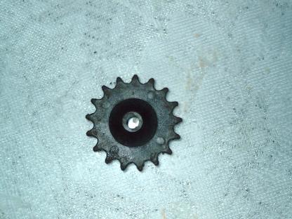
The previous owner/owners lost a couple of the black plastic "roller chain sprockets" so I will either have to buy replacements or make my own.
Notes:
Chain roller diameter of .195"
Sprocket teeth = 17
Sprocket pitch = .305" approx
Hole dia .238"
Gear thickness = .108"
Hub thickness = .048"
Hub thickness = .228"
taper largest = .915"dia
taper narrowest = .385" dia
(note curved taper)
============
Overall thickness .384"
Most likely the original was a black nylon gear. It may be a glass filled nylon as it seems to be very hard and rigid.
Update 2/15/17
My options are to draw it in CAD or scan it using my Roland Picza scanners Pix-3 or Pix-4. I tried using an online sprocket generator and entered the dimensions- I was able to import it in CAD software "Solvespace" but the dimensions are all wrong and creates a very tiny/miniature gear- so the gear generator doesnt output a proper DXF file. Also I see that the gear drawing is very rudimentary with a very sharp tip - where it is not a real-world ready-to-go drawing. I have to keep looking for another online sprocket generator.
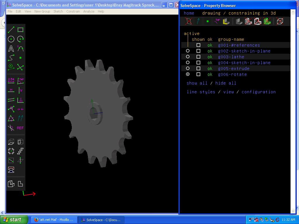
I have used CAD software and my old Dell Inspiron 2650 laptop running Windows XP to model this elusive
hard-to-find-a-replacement-for sprocket. I have been searching for parts for years unsuccessfully. Here are 2 screenshots of my DIY gear which I feel is ready to be test 3d printed and will probably take several attempts to get a good print from ABS plastic as I will have to try various settings for supports and temps etc so I get the best end result. Also since the actual cutout was modeled using 3 beziers. I may have to tweak the shape of the tooth for best fit. So far so good. I own 2ea 3d printers (heavily modified Alunar R100 and factory stock Stratasys Genisys Xs) and I will decide which one to use for creating this gear. My Stratasys printer uses a very hard brittle Polyester. The Alunar Ive only used ABS in the 1-1/2 years Ive been modifying it. So it comes down to those 2 materials as my choices. I think I need to make 3ea gears to complete the chain drive system. This gear is never imersed in chemicals - so the plastic doesnt need to be chemical-proof.
Later I will need to make the pin that goes in the yellow drive belt to make the length of yellow "rope" into a circle and connect both ends together. My full-size Magi Trak didnt come with this- the previous owner(s) lost those parts And I have been unable to find any parts or closeup photos of it.
Later I will need to make a magnetic dogbone (which actually pulls the film through the machine's chemistry) as that part was lost by the previous owner(s) also. I did have 2 emailers years ago but they didnt provide all of the photos I needed to understand the inner workings. I will need to invent my own version based on the limited photos I have of the dogbone.
Here was a link regarding a Bray Magitrak but this video is no longer active (not my video and I got no response from author who is somehow affiliated/employed by/with Raspberry Pi prototyping company) I suspect this machine was dumped as the autoe was showing it running outside and had dirt and debris from being outside. You cant leave a machine outside- even though its made of PVC and chemical proof. I hope it didnt get trashed and dumped- it was a half-size e-6 processor and a female owner asking for people who would like to partner with her to process e-6 film. I suspect that idea fizzled and the machine was junked and trashed. I never did get any response to my inquiries. What a waste of a machine left outside. That horrible jumpy video is the only time Ive ever seen a working Magitrak.
http://www.youtube.com/watch?v=ni5FX884Zqg
Thankyou to Paul Kra____ (2016 emails) and Ole Henri____ (2014-215 emails) for their emails several years ago and some snapshots of their own unit- these units were not the same model as mine - but it helps me to understand what my missing parts may look similar to.

|
Bray Magitrak Photos Paul Kra___ 2016 emailer Part 1.zip Size : 10689.886 Kb Type : zip |
|
|
Bray Magitrak Photos Paul Kra___ 2016 emailer Part 2.zip Size : 14092.037 Kb Type : zip |
Somewhere on old flashdrives or CDROM/DVDs or a failed computer hard drive I have photos from Ole Henri___ 2014-2015 but at this moment I dont know exactly where it is. He had a C-41 unit (mine is E-6) and he had offered to sell me some parts but I didnt have the funds at the time and that deal for his spare parts fizzled. Later when I contacted him to try and buy again - he had sold all of the extra parts and his entire machine. Dont you hate it when computer and hard drives fail?
Nowadays I only store information on USB flashdrives. Hard drives are great when they work and a great loss of information when they fail.
I retrieved these old photos from my Yahoo/Att mailbox as who knows when they will delete my old messages and photos. These were photo attachments to emails which I put in zip files.
Unfortuately some emails were from a drop box which no longer is retrievable. So hopefully I have those somewhere.
The magic of 3d printers is something I could only dream of a few years ago. Now I actually have 2ea 3d printers (and one more that I havent gotten around to fully restoring - and doesnt work yet) and Im enjoying every minute of restoring my previously impossible to fix machines. Because I WANT TO PROCESS FILM in my very very rare Magitrak from approximately 1980 year. Im juggling the restoration of several machines.
see my webpages about my 3d printers
http://www.drviragopete.com/3d-printed-parts-gears.php
http://www.drviragopete.com/stratasys-genisys-restoration.php
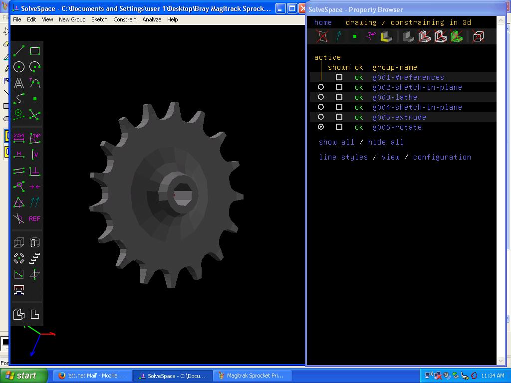
Here is my CAD drawing of this gear of which Im missing 3ea. I used Solvespace version 2.3tilde7c1ca460 (files created on February 16, 2018) to model this and is hand drawn. The gear is made with beziers for the notch and may need to be tweaked to fit perfect. I have also included the STL file which was generated by Solvespace. The more I use this software - the more I like it. I learned this software in January 2018 and my skill level is growing exponentially. It should be just fine for use as an idler with the miniature chain rollers. The mfg chose this oddball miniature chain size rather than standard bicycle chain. My only option is to make my own replacement part.

|
Bray Magitrack Sprocket V1_3 revolved (bezier notched 17x).slvs Size : 1155.697 Kb Type : slvs |
|
|
Bray Magitrak Sprocket Bezier Notched.stl Size : 65.316 Kb Type : stl |
After a failed attempt at support material 3d print, I stopped the print as the Cura software created gcode running on my Alunar was causing the printhead to collide with the uneven support structure. There is something not right with support function either in my settings or a bug in the software?
I have decided to rework my drawing so it prints an incomplete part that I will need to CNC mill on my rotary axis to complete or possibly on my lathe. When this print completes I will check to see which machine can hold it better. I added some surface area for this 2nd operation.
Here is the reworked "latheable" drawing which now has a totally flat back so it will lay flat on the 3d printbed. And protrusion at front for lathe to hold. Backside of teeth been removed for 3d print- lathe will cut that later. The leftover remnant will be the front protrusion - which shouldnt interfere with its function.
I can see a need to upgrade my Alunar printer still further by adding a 2nd printhead - for soluble support material - which renders all of this sort of thing a moot point in the future- but I want to proceed and accomplish this.

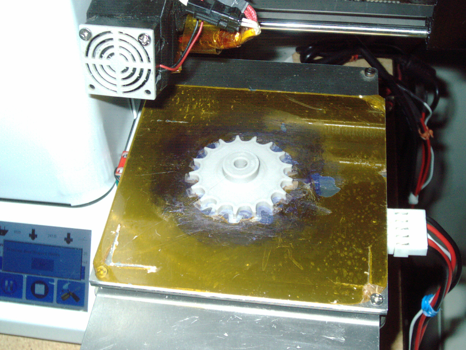
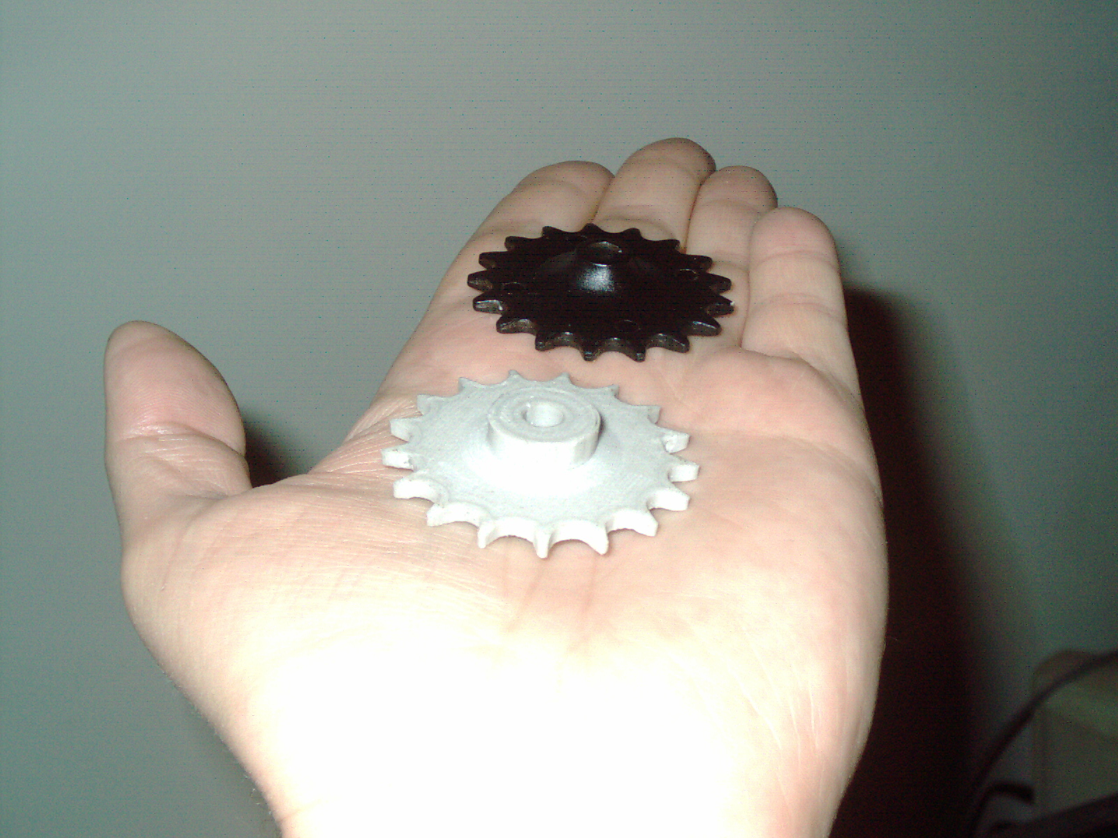
I feel like I have 2ea fully viable 3d printed gears now. I experimented with 3d printer settings and found the best temperature and feed rate to give a good result. One gear took 9 hours and 57 minutes at .1 resoution 100% infill and very very slow rate for best results.
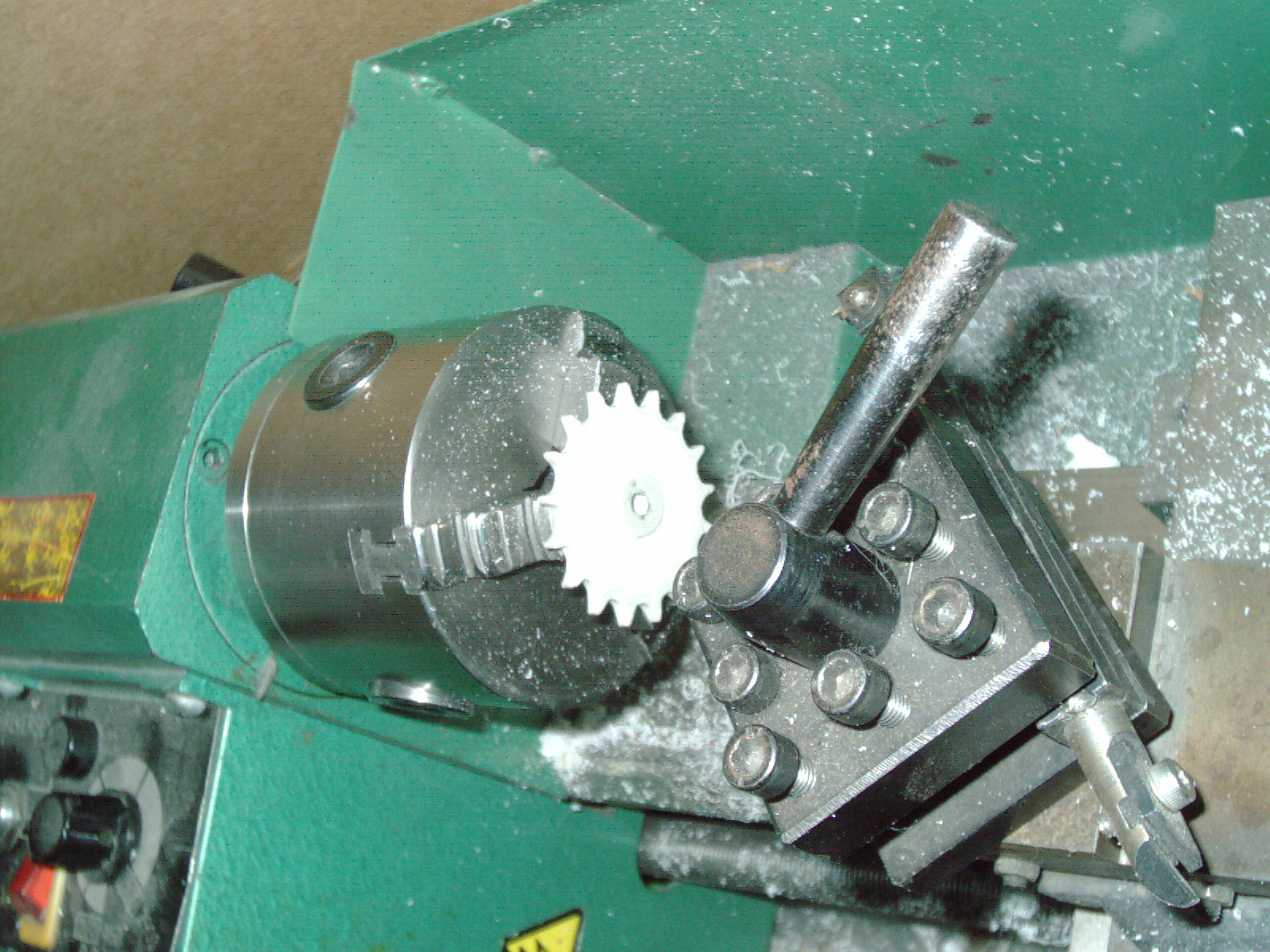
The lathe cutting of the DIY part was successful and didnt crack or break- I took my cuts very carefully and delicately. I feel like my second gear is much better than my first one - but nonetheless both are very good and useable. I feel like a burden has been lifted. I now have the ability to make these missing parts which were troubling me for a long time. I test fitted the gears onto the actual unmounted chain - and is a good fit.
Update 2/20/18
I have been looking at these photos for years off and trying to understand this complicated machine and parts from ragtag photos of a broken down machine in someone's garage. I was sent a handful of photos of someones mid-sized machine - which I appreciate. I have never seen anyone in real life with with these parts or even a video of how it works. Its one thing to see the parts in front of you - but I have to interpolate incomplete information and make a mental image of what it looks like. It wasnt obvious how it worked or how it fit together. Sometimes I had an AHA moment where it dawned on me how one component fit in with another component.
The thing that was the most difficult to figure out was - what is the purpose of the 3-part handle? I mean I was looking for linkages or springs or mechanisms. I always felt like I didnt have enough photos of this box. But I realize now - that the plastic itself flexes - like spring. By bending the handle - the plastic flexes and allows the lid of the box to raise up and over the 2ea one-way nubs. This 3-section handle allows that strip of PVC to make a curve. It is very possible that the metal pieces sticking out of the handle (this baffled me for years) was someone's DIY nuts and bolts after losing the original nut and bolt. It is doubtful that the mfg would make metal things sticking out like that.
Also visble in this photo is the knob which has a flat side. This can be turned as a latch - either allowing the lid to slide out or not. The one-way nubs are a way to only allow the lid to open so far- just far enough to allow the magnetic dogbone to get out of the box - after it is inserted into the machine's mouth opening. The machine's mouth and the outline of the box forms a light-tight seal with the help of some camera seal cloth (looks like black felt)

The rest of the box uses L-shape edges which are most likely connected with PVC cement as I dont know of any other way to attach PVC to PVC. The L-shaped edges would make it light tight.
The next thing is the magnetic dogbone and where does it go - in all of this process - where does it get inserted and when the processing is over - where does the magnetic dogbone go? Does it get discharged at the other end?
I see a V-shaped notch inside the "Removeable film magazine" and my hunch is that is where the magnetic dogbone goes. My hunch is the roll of film (or 2ea at once) is connected to the magnetic dogbone with tape - and gets the lid closed on the "removeable film magazine" box. I think that is where the journey begins for the magnetic dogbone.I will measure my own machine's "mouth" opening and figure out the dimensions of my missing removeable film magazine based on those dimensions. From there I will be able to make a CAD drawing. I dont have any reference for much of it so my handle size and parts and pieces sizes and dimensions will be my best guess.
This B&W messed up photo is the only one I found that shows how the box goes in the mouth opening. the 3-section-handle is at the top. My full size unit has the gray PVC strip and black light seal cloth still in place - this is visible in this B&W photo and gets pressed to the top of the film magazine - when inserted. I see the B&W photo shows the locking knob is open - so the lid can be opened up to the one-way nub- which allows the magnetic dogbone to go inside the machine.

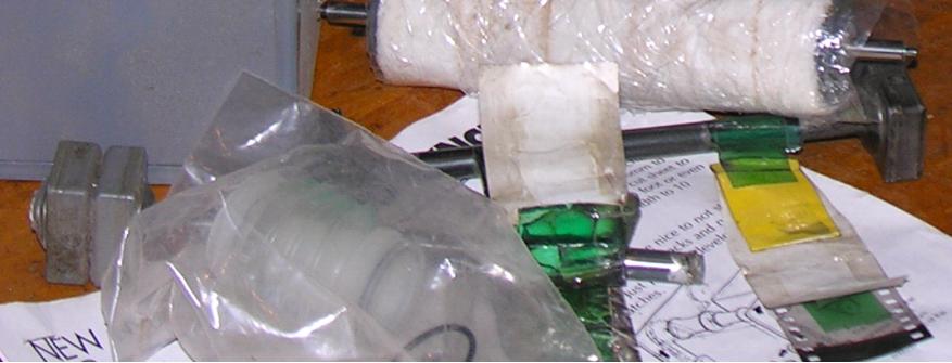
Looking at the good magnetic dogbone - it looks like there is a washer - and comparing that to the broken one I also see what looks like a washer. I can see green tape to attach the film to. There are 2 rolls of film which go inside the film magazine box - so it makes sense that the magnetic dogbone has 2 pieces of tape.


ERROR IN THE CARTOON DRAWING - the arrows in this cartoon are facing the wrong direction. This cartoon baffled me for years trying to figure out how the magnetic dogbone gets in the chaindrive - see the 2ea hooks would interfere. Those hooks catch the magnetic dogbone at the end. See the cartoon illustrates it as the beginning of the process- BUT NO it is the end of the process and arrows are drawn wrong. After the dogbone is visible at the end- then this film end is attached to the roller which is driven by the rubber "rolling pin" and this pulls the film through the rest of the way.
My guess is the magnetic dogbone is to pull the leader through- but then the film magazine box has the magnetic dogbone inside? This is still not clear to me. A person has to bea ready at the other end of the machine - so the process timing wont be interrupted and they attache the film to the roller. If it is a leader that gets fished through - then the attachment of the film in the loading box - to the leader is not clear - when that takes place.
Dr Virago Pete (847) 454-7858 between 11am and 7pm daily
drviragopete@att.net
Illinois USA